
Abstract
To help achieve zero carbon emissions from inland waterway vessels, this implementation of oxy-fuel combustion on a practical diesel engine at the economical oxygen-fuel ratios were systematically studied and analysed in this paper. A 1-D simulation was used to explore the effect of various operating parameters for recovering the engine power when the engine is modified to the oxy-fuel combustion from conventional air combustion. The brake power of oxy-fuel combustion is only 26.7 kW that has a noticeable decline compared with 40 kW of conventional air combustion with fixed consumption of fuel and oxygen. By optimising some valuable parameters, like fuel injection timing, intake charge temperature, intake components, engine compression ratio and water injection strategy, a benefit of 6.8 kW has been acquired in the engine power. Afterwards, a remarkable benefit was obtained with the increase of lambdaO2 from 1.0 to 1.5, finally obtaining the same engine power with the conventional air combustion. Above all, taking advantage of various operating parameters, it is expected to further improve the value of the implement of oxy-fuel combustion on diesel engines at the economical oxygen-fuel ratios.
Introduction
During the last few decades, the human-made impacts on climate has started to pose a significant threat to the planet. The impacts are largely linked to an increase in the naturally occurring Greenhouse Gas (GHG) emissions.1–5 Statistics show that the level of atmospheric Carbon Dioxide (CO2) has increased continuously since the Industrial Revolution, and it is generally recognised as the main factor to the climate changes. 6 Thus the concept of nations becoming ‘carbon-neutral’ is broadly accepted to avoid further deterioration of atmosphere due to GHG emissions.2,3 Through the implementation of strict emission standards, the European Union (EU) now also requires to reduce carbon emissions from the non-road mobile machinery. 7
Hence, to meet the carbon neutral targets, it is also mandatory to cut the carbon emissions from the Inland Waterway (IW) vessels. These vessels usually adopt Internal Combustion (IC) engines fuelled with diesel as their primary power source. Some recent innovative technologies, like hybrid electric, plug-in hybrid electric, battery electric, fuel-cell and solar-powered, have been shown to help achieve near-zero carbon emissions for diesel engines. Nevertheless, due to the bottlenecks in the power output and the high cost of these technologies mean that their application is currently limited only to in light-duty passenger vehicles rather than vessels. The Carbon Capture and Storage (CCS) technology has been widely considered as a promising solution to reduce CO2 emissions from fossil fuel power generation. 8
The chemical reactions for Conventional Air Combustion (CAC) and Oxy-Fuel Combustion (OFC) are shown in equation (1) to equation (2), respectively. The distinguishing feature of oxy-fuel combustion is the reactants and products. Table 1 below indicates the physiochemical properties of CO2 and N2, which plays an important role in the IC engine. Oxygen, which affects the emission level of nitrogen oxides in CAC, is still employed as the oxidiser for combustion. In the OFC, the final products only consist of H2O and CO2 theoretically, hence nitrogen oxides can be eliminated.


Due to the characteristics mentioned above, it is of great value to utilise oxy-fuel combustion technology on IC engines. In 1983, the Closed Cycle Diesel Engine (CCDE), known as the non-air-breathing diesel engine, was the first typical application of OFC with CCS in mobility. This diesel engine can achieve zero harmful emissions on the environment. 16 Reader and Hawley 17 concluded that CCDE is very suitable for the powertrain of submarines by virtue of low cost, high energy density, high security and low emissions. Hawley et al. 18 demonstrated that the compared to conventional combustion mode, the overall effect of engine performance would be power reduction and fuel consumption deterioration under oxy-fuel combustion. Wu et al.19–21 indicated that there is an improvement for the combustion performance and emission level of CCDE, in this way that the ethanol or gasoline is added into the inlet port even the direct-injected fuel remains diesel. Bilger 22 firstly proposed a concept named Internal Combustion Rankine Cycle (ICRC) system. In this case, the water is directly injected into the cylinders and CO2 can be captured by the after-treatment system or reused by Exhaust Gas Recirculation (EGR). Bilger and Wu 23 also applied the idea of ICRC to piston engines and concluded that this type of vehicles could be very competitive in carbon-controlled applications.
From the references above, it seems to be of great value to utilise oxy-fuel combustion technology on IC engines of the IW vessels. In our ongoing research project named RIVER funded by the Interreg North-West Europe, OFC coupled with CCS is used to achieve a zero-carbon emissions for the engines of the IW vessels. The designed configuration for OFC in IC engines can be presented as Figure 1. The exhaust gas, which mainly contains CO2 and H2O, should be condensed, followed by the separation of liquid H2O. Subsequently, a portion of remaining CO2 is recirculated back to cylinders through an EGR system. Then CCS can be implemented effectively after water separation, resulting in the separation of CO2. Remaining CO2 can be stored and used for other applications. The scope of this article covers only the combustion process and its control. The process of CCS will be a different topic for a separate article.

General configuration of OFC technology in IC engines.
All the previous studies16–21 related to OFC in Compression Ignition (CI) engines have mainly focused on the operating conditions of lean-burn mode, in which the overall supplied air is generally excessive for the burning fuel. However, the consumption of oxygen is usually quite costly so that it will imply increasing cost at the lean-burn conditions with high air-fuel ratios. Hence, to improve the engine economic performance, it is necessary to facilitate the oxy-fuel combustion process within economical operating conditions, which are close to stoichiometric oxygen-fuel ratio. This kind of method has rarely been found in the existing publications, although oxygen consumption is the most critical cost factor in the OFC.
According to the project RIVER’s purpose, one-dimensional simulation with GT-Power software was performed to investigate the working process of an oxy-fuel combustion diesel engine at the economical oxygen-fuel ratios. This simulation’s target is to achieve the equivalent power output with the CAC mode when the engine is modified to the oxy-fuel combustion mode. Moreover, the consumption of oxygen should be saved as much as possible during the oxy-combustion process.
Methodology and modelling description
As this OFC study needs achieve the equivalent brake power with CAC, it is necessary to find an optimum condition at the stoichiometric oxygen-fuel ratio (lambdaO2 = 1) by exploring each operating parameter accompanying with a fixed amount of oxygen consumption. The definition of lambdaO2 can be explained as equation (3). Here,

If the power is still not recovered, the amount of intake charge (lambdaO2) can be increased in the final stage. The overall flow chart of technology roadmap can be presented as Figure 2 to illustrate this methodology in detail.

Flow chart of technology roadmap in this simulation.
The first step of this roadmap is to calculate the engine power by replacing the intake N2 with the same volume of CO2. Meantime, fuel injection timing is adjusted and optimised according to explore the variation trend of power performance. In turn, the intake charge temperature and components are also optimised under the previously optimised fuel injection timing. Afterwards, the potential of brake power can be explored by increasing engine compression ratio in the next section. Then, to maximise brake power, the technical measure of water injection is employed as well as accompanying all the optimised parameters previously. Finally, if the brake power is still less than 40 kW, the goal can be achieved by increasing lambdaO2, and the comparison between OFC with CAC will be performed. All the results and discussions in the process towards the study’s target are described in the next sections, and the effects of each parameter are also systematically analysed in the meantime.
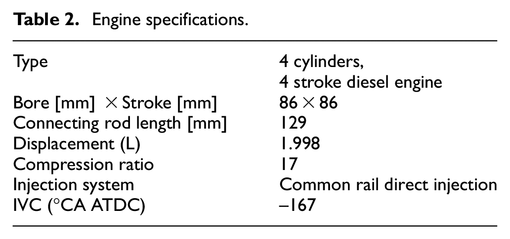
The simulation study was set up based on a commercial high-speed diesel engine which specifications are shown in Table 2. The high injection pressure can be realised by the common-rail injection system, leading to an improvement in the fuel economy and particle emissions.
Engine specifications.
The selected model of heat transfer and combustion in this simulation of GT-Power is ‘Woschni model’ and ‘Direct-injection diesel multi-pulse combustion model’, respectively. Some important parameters in this model can be explained with this formula below.

Here,
Here,
This model has been validated with experimental data for the operating working condition of CAC as Table 3, and the result is shown in Figure 3. The two cylinder pressure curves for simulation and experiment are nearly coincident. The position and degree of the peaks of curves have been well predicted. The features indicate that this model is capable of being used for this research.
Engine operating conditions in the condition of CAC.


Comparison of cylinder pressure between experiment and simulation under CAC mode.
Besides, the fuel injection mass and timing is fixed and equal to the value of CAC throughout the simulation research of OFC.
In order to achieve flexible control and stable operating conditions of OFC mode, there should be some useful changes to the engine. In the practical applications, it is essential to establish effective systems to implement the functions of oxygen feeding, intake organisation, water/fuel injection, CO2 separation, capture and storage, etc.
As shown in Figure 4, the system of engine intake charge should be modified. The oxygen can be fed into the inlet with one of the two typical oxygen feeding strategies, then enters into the engine cylinders accompanied by CO2. In this model, the strategy in Figure 4(a) was chosen to realise the transformation from CAC to OFC. Hence, the implemented method to realise OFC can be simplified without considering the EGR system and strategy. The simulation can redefine the initial ambient only involves oxygen and CO2, and the relevant parameters can be flexibly changed, such as intake charge temperature, intake component and mass flow rate. In the practical application, these parameters can be controlled by the utilisation of valves, flowmeters, heaters and mixer.
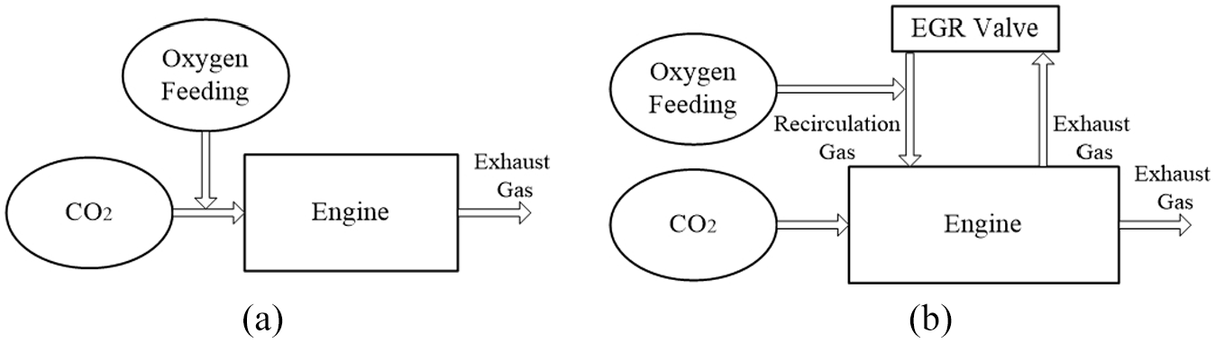
Schematic of typical oxygen feeding strategies in IC engines: (a) oxygen feeding without EGR and (b) oxygen feeding with EGR.
Despite that there is a risk to enhance corrosion of engine from moisture, water injection is still a considerable way to simultaneously achieve the target of maximum engine performance and avoid the knock’s damage. For the oxy-fuel IC engines, water injection technology has hitherto been adopted as a technical way to optimise combustion.23,24 Its current typical strategies can be presented in two types as Figure 5. In this model, the strategy of Figure 5(a) was selected due to its compact and practical control platform.
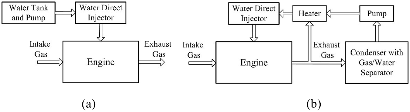
Schematic of typical water injection systems in IC engines: (a) water injection with water tank and (b) water injection without water tank.
In this paper, the authors focus on a feasibility study of implementation of OFC on a practical diesel engine at the economical oxygen-fuel ratios by 1-D simulation. Rest of the paper is arranged as follows: replace N2 with CO2 and recovering power by optimising injection timing, then recovering power by optimising intake charge temperature, intake charge components, engine compression ratio and water injection strategy, finally comparing between OFC of increasing lambdaO2 and CAC, as well as the conclusions.
Results and discussion
Replace N2 with CO2 and recovering power by optimising injection timing
In this CI engine, diesel can be directly injected to cylinders by a high-pressure common rail, leading to that the fuel droplets can break up into tiny droplets quickly. This can help to improve the quality of vaporisation and atomisation, resulting in that a higher homogenous air-fuel mixture which is beneficial to promote complete combustion. Thus it is essential to find an optimal injection timing to improve the thermal efficiency for enhancing the engine power.
Due to the difference between the property of CO2 and N2, especially that the thermal diffusivity of CO2 is only 64.4% of N2 which can reduce the rate of flame transmission and heat transfer during the combustion process. Therefore, when the N2 of intake charge is replaced with the same volume of CO2, and all the other factors keep constant in the meantime, it is notable that brake power of OFC decreases significantly to 26.7 kW which is 13.3 kW less than that of CAC in Figure 6.

Effect of injection timing on brake power and cylinder pressure.
Besides, the reduced power can be recovered slightly in a certain range of advanced injection timings, continuously from 25.2 kW to 29.0 kW with the injection timing advances from −2 ‘CA ATDC’ (hereinafter referred to as ‘CA’) to −22 °CA. Furthermore, as the power becomes essentially constant around 29 kW and is not easy to be further improved with earlier injection timings, −22°CA can be an optimised injection timing selection under OFC mode.
It can be seen that the curves of cylinder pressure also change a lot with different injection timings. Almost all the curves exhibit a bimodal distribution form in the OFC mode. All the first peaks which occur around −2°CA mainly reflect maximum cylinder pressure without combustion. Afterwards, the cylinder pressure will slightly decrease owing to the heat absorption of fuel droplets in the combustion chamber, followed by a rapid renewed increase after a couple of degrees. The curves’ second peak which occurs during the combustion process increases significantly up to more than 90 bar as the injection timing advances, and the appearance of the peaks become earlier from 20°CA to around TDC.
The performance under various injection timings can also be illustrated by the Heat Release Rate (HRR) and in-cylinder temperature in detail. As shown in Figure 7, with an advanced injection timing, all the HRR curves and the CA50 (the crank angle where 50% fuel energy is released) are advanced to a proper and finite crank angle period. This is a benefit to enhance the engine power because the heat supply can be ensured in an approximate constant space and occurs much faster, which is closed to an idea constant-volume process and helps to increase the pressure at the initial stage of combustion. Figure 8 shows that the maximum in-cylinder temperature also gets an apparent improvement from 1433.8 K to 1565.6 K with the advance of injection timing. The effect of the relatively higher temperature is beneficial to speed up the burning rate. Thus a larger fraction of fuel’s energy can be transferred at the start of expansion to the piston as work.

Effect of injection timing on HRR and CA50.

Effect of injection timing on in-cylinder temperature.
Recovering power by optimising intake charge temperature
Regarding the practical operation of diesel engines, the intake charge temperature can be changed by employing an intercooler to increase intake density, leading to an improvement for the volumetric efficiency. Hence, to estimate and analyse the potential of the intake air temperature on recovering the engine power under OFC, varying intake charge temperature on brake power and combustion characteristics is carried out in this simulation study. Meantime the intake mass should be kept constant by adjusting the intake pressure when the intake temperature changes during the simulation.
Figure 9 shows that with the increase of intake temperature, the power shows a slight reduction from 28.4 kW to 27.9 kW under the operating condition of −12°CA injection timing, and a 0.9 kW reduction would occur under the condition of −22°CA injection timing. The power almost remains constant under the operating conditions of 283 K and 298 K. Therefore, 298 K is selected of the two as the intake temperature in the following sections of this simulation, because it is the normal room temperature which is easy to be implemented and more suitable for heating the engine.

Effect of intake air temperature on brake power and cylinder pressure at IVC timing.
With the increase of temperature, the following factors would have a negative influence on the brake power. Firstly, in order to introduce the same amount of intake mass, the intake pressure should be enhanced due to the reduction of intake density. Therefore, as shown in Figure 9, the cylinder pressures at Inlet Valve Closed (IVC) timing shows a slight increase by 0.159 bar and 0.163 bar under the conditions of −12°CA and −22°CA injection timing, respectively. Secondly, increasing the intake air temperature can advance the combustion process, owing to accelerate the evaporation and atomisation of fuel droplets. Hence, as shown in Figure 10, the peak of HRR is advanced by several degrees. Besides, CA50 is undesirably located in the angles of the compression stroke, which has a negative effect on the enhancement of HRR.
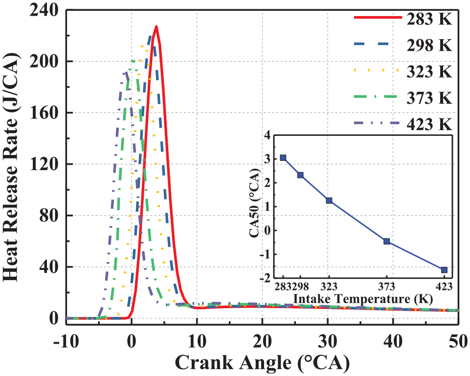
Effect of intake charge temperature on HRR and CA50 (injection timing = –22°CA).
Recovering power by optimising intake charge components
During the combustion process, the oxygen is utilised as an oxidiser which concentration affects the combustion process profoundly, including the ignition delay, flame speed and cylinder temperature. In this section, the fraction of CO2 is a variable factor ranging from 70% to 79.7% in volume to investigate the effect of optimising intake charge components on combustion performance and recovering power under OFC mode. Meanwhile, the oxygen fraction can be improved up to 30% in volume, whereas it does not represent a higher mass amount for oxygen consumption due to the fixed oxygen mass flow rate.
Figure 11 shows that as the CO2 fraction decreases from 79.7% to 72%, the brake power generally increases monotonously by approximate 1.8 kW, whereas the curves start to flatten out with the further reduction of CO2. The reason is related to the cylinder pressure at IVC timing which has declined by 0.335 bar and 0.327 bar for the condition of −12°CA and −22°CA injection timing, respectively. It is also caused by the variation of HRR and CA50 in Figure 12. As the decrease of CO2 fraction from 79.7% (‘20.3/79.7’ in the figure) to 70% (‘30/70’), even the curve is significantly postponed and CA50 increases from 2.32°CA to 7.43°CA, it is still in the reasonable range which can facilitate the complete combustion. Besides, the peak of HRR increases from 172.45 J/CA to 295.33 J/CA, leading to a promotion to the output of engine power. All of these factors contribute to enhancing the power output even that the consumption of fuel and oxygen is fixed. Hence the optimised intake components for oxygen and CO2 is selected at 28% and 72% in volume.

Effect of intake components on brake power and cylinder pressure at IVC timing.

Effect of intake components on HRR and CA50 (injection timing = –22°CA).
Recovering power by optimising engine compression ratio
For a diesel engine, as compression ratio increases, the thermal efficiency of the engine can be improved as well. As the compression ratio generally ranges up to 22 for commercial conventional diesel engines currently, the compression ratio is set up with 17, 19.5 and 22 in this simulation research. Also, the optimal injection timing is likely to be slightly varied under different compression ratios, so a variety of timings should be investigated in this section for better recovering the engine power. As shown in Figure 13, the enhanced power by increasing the compression ratio can be a considerable value of 3.5 kW under the conditions of −7°CA injection timing, whereas it just improves by 0.5 kW as the injection timing increases to −17°CA. Moreover, it is notable that the maximum brake power is usually achieved at the compression ratio of 22 except the condition of −22°CA injection timing. The exception with −22°CA injection timing can be explained by the related HRR and CA50, which is quite advanced by the increased compression ratio. The start of heat release can be advanced by 10°CA, which would result in an offset to the boost of brake power by the increasing heat losses during the compression stroke. To analyse the apparent gain by increasing compression ratio under the injection timing of −7°CA, Figure 14 illustrates that the peak of cylinder pressure is enhanced significantly from 53.16 bar to 94.93 bar as the increase of compression ratio. Furthermore, the heat release is still kept in the proper range, which peak is several CA after TDC. Therefore, the positive effect of increasing compression ratio to recover the power of diesel engines under OFC mode is limited by the range of injection timing. Therefore, as the maximum power can be obtained by the compression ratio of 22 accompanied with the injection timing of −7°CA and −12°CA, these parameters are kept in the following sections of this simulation.
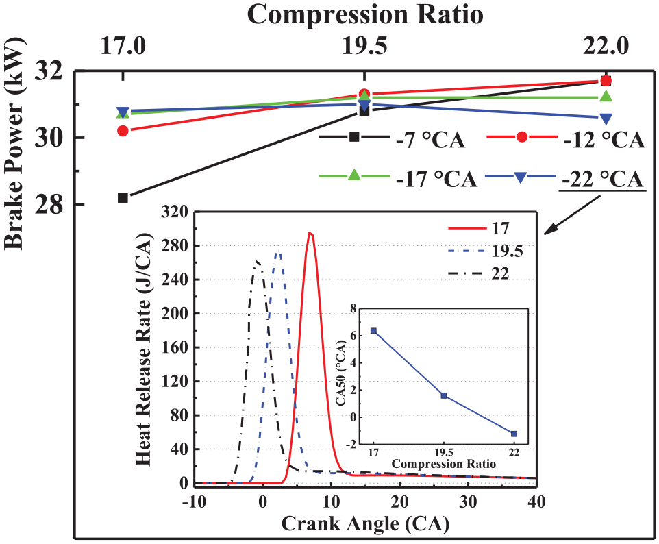
Effect of compression ratio on brake power; the HRR and CA50 (injection timing = –22°CA).

Effect of compression ratio on HRR and cylinder pressure (injection timing = –7°CA).
Recovering power by utilising water injection strategy
Recent years, water injection strategy has been an advanced technology to inhibit knock by reducing the in-cylinder temperature of IC engines. The constant pressure process can also be extended as the result of the water evaporation at the beginning of the power stroke. 24 Furthermore, water injection strategy has also been adopted as a useful measure to optimise the combustion process for oxy-fuel engines.25,26
In this section, the effect of water injection strategy to recover engine power is explored in detail. Water liquid with an initial temperature of 298 K is directly injected into cylinders. To better understand the influence extent of water injection mass and timing, the injection mass ranges from 1 mg to 5 mg per cylinder per working cycle, and the succeeding part for water injection timing ranges from −120°CA to −40°CA.
In Figure 15, it is observed that the brake power can be enhanced by increasing the water injection mass with a fix injection timing at −100°CA. By this way, not only more working medium is added, but also burn rate is also accelerated owing to that both the oxygen concentration and the flame propagation process are changed. However, the influence extent is not very obvious, which only has a slight increment by 0.9 kW and 1.1 kW as the water injection increases from 0 mg to 5 mg under the condition of −7°CA and −12°CA fuel injection timing, respectively. It is because the excessive injected water can lead to a slight positive effect on cylinder pressure and heat release rate, as shown in Figures 16 and 17. Meanwhile, the phasing of combustion cannot be easily changed by water injection. Under the cases of 5 mg water injection, CA50 is just postponed by 2.18°CA. Besides, as the maximum 32.8 kW is obtained under this condition of −12°CA injection timing, so it was selected in the following sections about recovering the engine power.

Effect of water injection mass on brake power.

Effect of water injection mass on cylinder pressure (injection timing = –12°CA).

Effect of water injection mass on HRR (injection timing = –12°CA).
Unlike the tendency with increasing water injection mass, the effect of different water injection timing on engine power is a bit complicated, as shown in Figure 18.
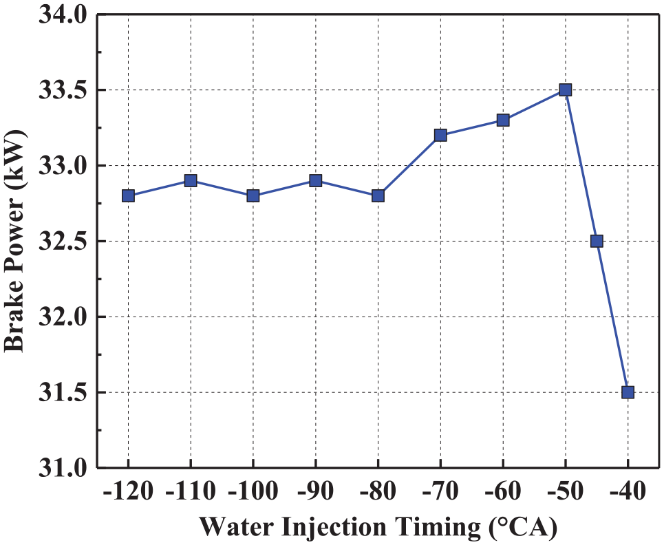
Effect of water injection timing on brake power.
As the water injection timing postpones from −120°CA to −80°CA, the brake power keeps broadly stable. With a further delay, the brake power commences a gradual rise to 33.5 kW at −50°CA then it decrease rapidly to 31.5 kW at −40°CA. The changes tendency with water injection timing can be mainly attributed to the two aspects. Firstly, owing to the postponed from −120°CA to −50°CA, it can ensure higher efficiency to utilise the injected water to increase the working fluid. However, in the case of −45°CA and later injection timings, the duration of water injection will interrupt the fuel atomisation, leading a strong negative effect for the early stage of combustion process which displays an abnormal in the curve of cylinder pressure in Figure 19. This instability characteristic had also been demonstrated in the experimental study of the existing publication. 26 Secondly, as shown in Figure 20, the combustion phasing is postponed with the delay of water injection timing, which leads to a slight reduction of the peak of cylinder pressure in Figure 19.

Effect of water injection timing on cylinder pressure.

Effect of water injection timing on HRR.
Comparison between OFC of increasing lambdaO2 and CAC
Based on the study roadmap presented in Figure 2, in order to obtain the same power out with the CAC, the final step is increasing the intake mass, leading to the growth of lambdaO2 with 0.1 intervals until the power is not less than 40 kW. The effect of lambdaO2 on recovering power under OFC is in shown Figure 21. As the lambdaO2 increases from 1.0 to 1.5, the brake power has significantly improved from 33.5 kW to 40 kW, even though other operating parameters keep constant. It is regarded as the eventual solution to recovery engine power in this simulation research. With the increasing amount of intake charge, the effective value of adiabatic index during the expansion process will be increased. It will enhance the fuel conversion efficiency at a given expansion ratio, resulting in higher expansion stroke work for per unit mass of fuel.

Effect of lambdaO2 on brake power in oxy-fuel combustion.
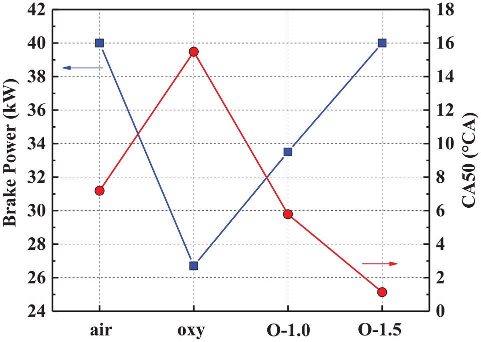
Figures 22 and 23 illustrate the comparison between OFC and CAC, including brake power, CA50 and HRR. The ‘air’, ‘oxy’, ‘O-1.0’, ‘O-1.5’ is introduced to represent the previous simulation case of conventional air combustion, initial OFC (replacing the N2 with CO2), optimised OFC (lambdaO2 = 1.0) and final OFC (lambdaO2 = 1.5), respectively. It can be found that CA50 is significantly delayed from 7.18°CA to 15.48°CA when the N2 is replaced by CO2, which seriously affects the peak of cylinder pressure and power out. However, the engine power obtains an apparent recovery by using all the proposed optimisation solution in the technical roadmap, achieving 40 kW by increasing lambdaO2 eventually.
Comparing of brake power and CA50 between oxy-fuel combustion and conventional air combustion.

Comparison of HRR between oxy-fuel combustion and conventional air combustion.
Conclusion
This research is about a feasibility study for the implementation of OFC on a practical diesel engine at the economical oxygen-fuel ratios using 1-D simulation. It is a research conducted part of the project RIVER (funded by the Interreg North-West Europe), to promote the design of one OFC diesel engine coupled with CCS technology to achieve zero carbon emissions from IW vessels.
In this simulation, when the engine is modified to the OFC, it achieves the equivalent power output with the CAC mode by utilising some technical measures. Moreover, the consumption of oxygen should be saved as much as possible during the oxy-combustion process. For this purpose, various parameters including fuel injection timing, intake charge temperature, intake components, engine compression ratio and water injection strategy, have been used and optimised for the OFC engine’s power performance. The brake power of oxy-fuel combustion is only 26.7 kW that has a noticeable decline compared with 40 kW of conventional air combustion with fixed consumption of fuel and oxygen. Based on the roadmap of this study, after optimising a lot of valuable parameters, the obtained maximum brake power is 33.5 kW, which is still 6.5 kW less than the conventional air combustion. However, a benefit of 6.8 kW has been acquired from this optimisation method. Afterwards, the increasing lambdaO2 from 1.0 to 1.5 can bring remarkable improvement to brake power, resulting in the same power with the conventional air combustion. In the meanwhile, some significant conclusions of this research can be summarised as follows:
The brake power has grown continuously from 25.2 kW to 29.0 kW when the injection timing advances from −2°CA to −22°CA. With a retarded injection timing, the peaks usually present decrease trends for all curves of cylinder pressure, HRR and cylinder temperature.
Within a certain range, decreasing intake temperature or CO2 fraction can be a helpful way to recover the engine power.
The effect of increasing compression ratio on power output would be limited by the range of injection timing. Because under the conditions of early injection timings, there would be an offset by the enhanced heat losses during the compression stroke.
The brake power can be recovered by increasing the water injection mass, while this effect is very limited. Besides, within a suitable range of water injection timing, the brake power can be enhanced.
By increasing lambdaO2 from 1.0 to 1.5, which is selected as the final solution due to enhance the oxygen consumption, can significantly improve engine power from 33.5 kW to 40 kW, even though other operating parameters are unchanged.
Footnotes
Appendix
Handling Editor: James Baldwin
Declaration of conflicting interests
The author(s) declared no potential conflicts of interest with respect to the research, authorship and/or publication of this article.
Funding
The author(s) disclosed receipt of the following financial support for the research, authorship, and/or publication of this article: The authors gratefully acknowledge the financial support of the Interreg North-West Europe (Project No. NWE553).