
Abstract
To further reduce the vertical stiffness of the air spring, appropriately reduce its lateral stiffness to attenuate the transmission of vibration along the lateral and longitudinal directions, a compound structure air spring (CSAS) was designed. It is a laminated structure with a hard elastic layer at the lower end of the original air spring. Prototypes of the air spring and the CSAS were produced, then related static and dynamic characteristics tests were conducted. Compared with the test results of the air spring, it can be found that under the same air pressure, the bearing capacity of the CSAS is decreased slightly; under rated load, the vertical static/dynamic stiffness and natural frequency is decreased slightly, and the lateral static/dynamic stiffness is decrease significantly. Furthermore, the CSAS was subjected to the safety and reliability tests, and its performance was stable without damage. This article expands the stiffness range of the air spring, and provides a new idea for the design of the air spring with low lateral to vertical stiffness ratio and low natural frequency.
Keywords
Introduction
Air spring is a kind of vibration isolation element with excellent performance, which uses the elasticity of compressed air to achieve vibration isolation and cushioning. 1 High working pressure air spring has been widely used in vibration isolation of large-scale ship power equipment. 2 To ensure the stability, its lateral stiffness is usually about 2–2.5 times the vertical stiffness.3,4 In recent years, with the continuous improvement of vibration control requirements, power equipment expects that the vertical stiffness of the air spring can be further reduced, and the lateral stiffness can be greatly reduced at the same time, so that the air spring can get a smaller lateral to vertical stiffness ratio. There are two technical ways to achieve this goal: one is to make significant adjustments to the structure of the air spring, but it may cause problems such as the reduction of the pressure strength of the rubber capsule, which is relatively difficult; the second is to connect a hard and elastic element in series on the basis of the original air spring to form a CSAS, which can significantly reduce the lateral stiffness.
Extensive research on compound vibration isolators has been conducted previously. In the railway locomotive field, a kind of flexocoil spring with rubber is widely used in the secondary suspension of rolling stock. A large number of studies have shown that this double-layer structure can reduce the flexocoil spring stress level and make its lateral stiffness greatly reduce.5,6
Laminated rubber structure is composed of rubber layer and metal layer vulcanized alternately, the advantage of this structure is that it has large vertical stiffness and small lateral stiffness. 7 Bearings and springs made of this structure can be used for vibration damping of bridge construction and elastic support of rolling stock. Haringx 8 first treated the laminated rubber bearing as an equivalent column with constant cross section area, homogeneous and isotropic material, and the equivalent height included the rubber layers and the metal layers. Chang 9 established a new analysis model of laminated rubber bearings based on Haringx’s theory, and studied the horizontal stiffness and buckling load of the bearings with different geometric parameters and boundary conditions. Salim et al. 10 studied the vibration transmission characteristics of laminated rubber bearing and confirmed that it can improve the high-frequency vibration isolation effect. In view of the fact that existing models for laminated rubber bearings neglect the lateral-torsion coupling property of their response behavior, Zhou et al. 11 proposed an analytical model considering the lateral-torsion coupling of laminated rubber bearings, which is used to evaluated the dynamic properties and torsional response of laminated rubber bearings.
Jiangtao et al. 12 designed a rubber steel wire rope compound vibration isolator, which can attenuate high and low frequency vibration and effectively improve the vibration isolation efficiency in the resonance zone. Tang et al. 13 conducted dynamic modeling and parameter identification of this compound vibration isolator, fitted the hysteresis and frequency response characteristics under different working conditions, and the fitting results are basically consistent with the test results.
However, compared with the air spring, the above-mentioned compound vibration isolators have some problems which cannot fulfill the requirements of various harsh working conditions of ships sailing on the sea. For example, the flexocoil spring with rubber may undergo greater bending deformation or even breakage under a large impact load; the laminated rubber structure has obtained greater load-bearing capacity and low lateral stiffness by embedding the metal layer in the rubber layer, but its vertical stiffness is increased, and the vibration attenuation effect is not obvious; the rubber steel wire rope compound structure has a good vibration isolation effect, but its load-bearing capacity is limited, and it cannot be applied to large-scale ship machinery.
So far, little research has been done on the CSAS. Heng-bo et al. 14 developed a compound air spring that is assembled with a capsule and a shock absorber, which greatly reduces the natural frequency of the suspension system, but it can only be used in the locomotive field. Shen et al. 15 studied the performance of a compound vibration isolation device, which is composed of an upper rubber spring and a lower air spring. It has excellent vibration isolation performance, but its bearing capacity is small. Du et al. 16 designed a compound air spring, which is connected in parallel with the elastic body wall outside the air spring, but its vertical stiffness is increased compared with the original air spring, and its bearing capacity is small, too.
The technical difficulties of the CSAS design mainly lie in the following aspects:
(i) The hard elastic layer should have sufficient rigidity, the amount of deformation under the rated load should be as small as possible, otherwise it will cause the rated air pressure to rise too much, causing many adverse effects; (ii) The hard elastic layer should have a certain degree of flexibility to reduce the stiffness of the CSAS; (iii) After the hard elastic layer is connected in series, the carrying capacity of the air spring should remain basically unchanged; (iv) When the ship is adjusted for tilting and swaying or subjected to a large impact load, the hard elastic layer can neither be damaged nor peeled off from the air spring; (v) The hard elastic layer cannot suffer fatigue damage under the action of cyclic stress and strain.
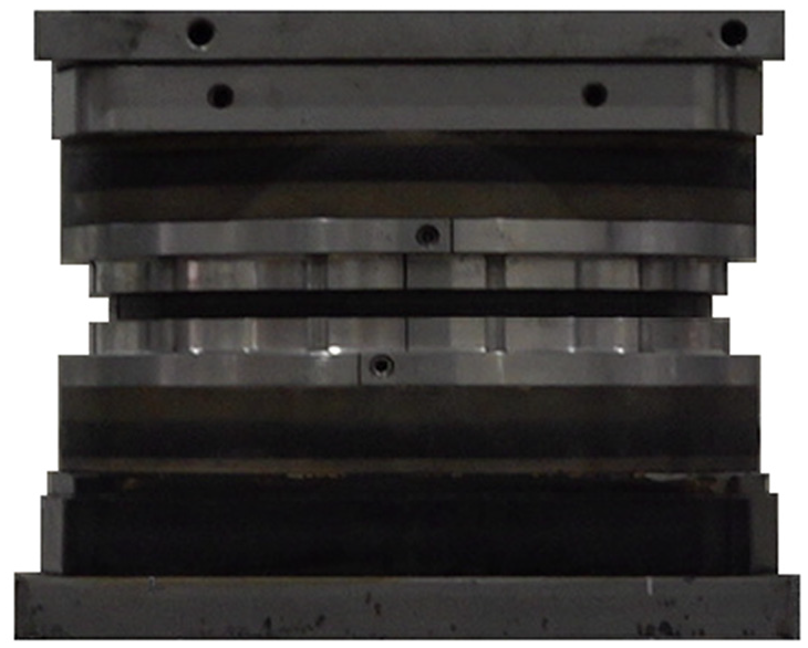
Figure 1 shows the structure of the high working pressure air spring, it is mainly composed of upper cover plate, lower cover plate, rubber capsule, limiter and inflatable connector. In view of the difficulties in design, and combined with the requirements of vibration control, the original structure of the air spring is kept unchanged, only the hard elastic layer is connected in series at its lower end, and a mounting base plate is added. Figure 2 shows the structure of the CSAS.

Structure of the air spring.
Structure of the CSAS.
Figure 3 shows the framework and research ideas of this manuscript, which is divided into five sections. In the first section, the research background and design requirements of the CSAS are introduced, and the technical difficulties in the design are pointed out; In the second section, the static characteristics tests are carried out, the air pressure-load characteristics, vertical and lateral static stiffness are analyzed; In the third section, the dynamic characteristics tests are carried out, the vertical and lateral dynamic stiffness are analyzed, and the natural frequency of the vibration isolators are calculated; In the fourth section, the safety and reliability tests of the CSAS are carried out to ensure the safe use under complex working conditions; In the fifth section, the main research contents and work of this manuscript are summarized, the research conclusions are elaborated, and the future work is prospected.

The framework of this manuscript.
Static characteristics tests of the CSAS
The air spring with rated load of 8 t is taken as the research object, and its rated height is 200 mm. Two prototypes of the air spring and the CSAS were produced for vertical and lateral static performance tests. Polyurethane material is selected as hard elastic layer, which has good wear resistance, wide range of hardness, high elongation, large load support capacity, and excellent oil resistance.17,18 The thickness of the hard elastic layer is 25 mm, and the hardness is 65 HA. It was subjected to a tensile test before vulcanization, and the Young’s modulus was measured to be 5.0 MPa, the tensile strength was 25–30 MPa, and the elongation was 460%–480%. The thickness of the metal mounting plate is 20 mm, so that the rated height of the CSAS is 245 mm. All tests are completed on a 50-ton MTS testing machine. In addition, the test equipment also includes: inflation device, force sensor, displacement sensor, vernier caliper, computer control device, etc.
Air pressure-load test
Fix the two types of the vibration isolators at the rated height, and the air spring is slowly inflated to increase the internal air pressure from 0.2 MPa to 2.4 MPa, with a step length of 0.2 MPa. From the air spring bearing calculation formula

Air pressure-load curve of the vibration isolators: (a) two measurement results of the air pressure-load curve and (b) fitting results of the air pressure-load curve.
It can be seen from Figure 4(b) that the linear relationship between air pressure and load is not changed after the hard elastic layer is connected in series; under the same air pressure, the bearing capacity of the CSAS is slightly lower than that of the original air spring. According to the curve fitting equations
The reason of load drop is analyzed. Firstly, the air spring is simplified as the model shown in Figure 5, in which (1) is the rubber capsule; (2) is the cover plate; (3) is the adjusting flange. 19 After the adjustment flange is designed and installed, the flange guide angle is determined, and to change the guide angle, a new adjustment flange should be designed and installed.
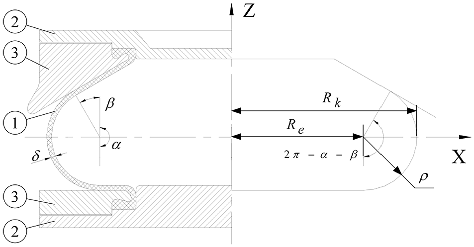
Simplified model of the air spring. 19
The bearing capacity of the air spring can be obtained by 20 :

Where
The effective radius

Where

Where
As shown in Figure 6 (The solid line shows the state of the CSAS when the hard elastic layer does not undergo compression deformation, and the dotted line shows the state of the CSAS after the compression deformation of the hard elastic layer), when the total height of the CSAS remains unchanged, the compression deformation of the hard elastic layer will cause the height of the rubber capsule to increase. The increment in the height is equal to the compression deformation of the hard elastic layer, both

Variation in the effective radius of the CSAS.
Static stiffness test
Polynomial fitting method for static stiffness
The static stiffness

Where
When

Where
Due to the non-linearity of the rubber capsule, the displacement-load curve of the air spring is a closed hysteresis curve, and there are different load values under the same deformation. It is not accurate to calculate the static stiffness by equation (5). Therefore, a polynomial fitting method is proposed.
The following equation is used to fit the deformation-load curve of vibration isolator 21 :

Where
When

When
Sampling the load-deformation curve under the rated air pressure at equal intervals, the following formula is given for the

The coefficient
The derivative of equation (7) with respect to deformation can be written as:

When
Vertical static stiffness test
Figure 7 shows the vertical static stiffness test of the CSAS. The upper hydraulic cylinder can move up and down according to the height of the vibration isolator, but it is completely fixed after the installation of the vibration isolator; a force sensor is installed at the lower end of the upper hydraulic cylinder, which can measure the load in real time; the inflation device can be used to charge and deflate the air spring, and the air pressure can be control by the pressure gauge; the lower hydraulic cylinder is equipped with a displacement sensor, which can measure the displacement. During the test, one end of the vibration isolator is fixed, and the other end uses displacement control, the peak-to-peak displacement (referred to as pp) is 1.0–7.0 mm, the step length is 1.0 mm, and the loading rate is 0.1 mm/s. By reading and drawing the vertical displacement-load curve on the computer, the vertical static stiffness of the vibration isolator can be calculated.

Vertical stiffness test.
The polynomial fitting is performed on the vertical displacement-load curves, and the polynomial degree ranges from 1 to 6. Table 1 lists the correlation coefficients under different polynomial fitting orders when pp = 1.0 mm.
Correlation coefficients under different polynomial fitting orders in vertical direction.

It can be seen from Table 1 that when the degree of the polynomial is greater than 3, the fitting correlation coefficient basically does not change, which shows that choosing the third-degree polynomial for fitting can achieve high accuracy. Too high polynomial degree cannot significantly improve the accuracy while increasing the amount of calculation. The fitting correlation coefficients under other pp values are consistent with the conclusion that pp = 1.0 mm, and they are not listed here. Therefore, a cubic polynomial is chosen to fit the vertical displacement-load curve.
Figure 8 shows the cubic polynomial fitting results of the vertical displacement-load curves, and Figure. 8(a) to (g) correspond to pp = 1.0–7.0 mm, respectively. It can be seen that the vertical static stiffness of the two types of vibration isolators both show nonlinearity.

Cubic polynomial fitting results of the vertical displacement-load curves: (a) pp = 1.0 mm, (b) pp = 2.0 mm, (c) pp = 3.0 mm, (d) pp = 4.0 mm, (e) pp = 5.0 mm, (f) pp = 6.0 mm, and (g) pp = 7.0 mm.
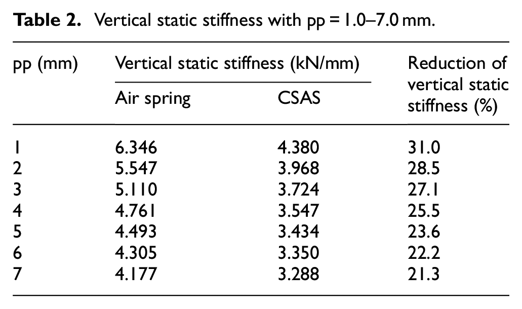
As shown in Table 2, the vertical static stiffness with pp = 1.0–7.0 mm can be obtained by putting forward the first-order term of the polynomial in Figure 8. It can be seen that when pp = 1.0–7.0 mm, the vertical static stiffness of the CSAS is reduced by 31.0%, 28.5%, 27.1%, 25.5%, 23.6%, 22.2%, and 21.3%, respectively. The vertical static stiffness of the CSAS can both be further decreased under different pp values.
Vertical static stiffness with pp = 1.0–7.0 mm.
Lateral static stiffness test
Figure 9 shows the lateral static stiffness test of the CSAS. Two identical vibration isolators are fixed on the lateral clamp at a rated height in pairs. After installation, the air spring is slowly inflated until the air pressure of each reaches the preset value. During the test, one end of the fixture is fixed, and the other end uses displacement control, pp = 1.0–5.0 mm, the step length is 1.0 mm, and the loading rate is 0.1 mm/s. By reading and drawing the lateral displacement-load curve on the computer, the lateral static stiffness of the vibration isolator can be calculated.

Lateral stiffness test.
The polynomial fitting is performed on the lateral displacement-load curves, and the polynomial degree ranges from 1 to 6. Table 3 lists the correlation coefficients under different polynomial fitting orders when pp = 1.0 mm.
Correlation coefficients under different polynomial fitting orders in lateral direction.
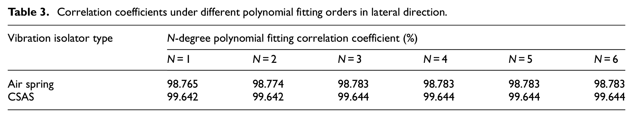
It can be seen from Table 3 that the situation is the same as that of the vertical static stiffness fitting. The third-order polynomial can be selected to better fit the lateral static stiffness of the vibration isolators.
Figure 10 shows the cubic polynomial fitting results of the lateral displacement-load curves. Figure 10(a) to (e) correspond to pp = 1.0–5.0 mm, respectively. It can be seen that the lateral static stiffness of the two types of vibration isolators both show nonlinearity.

Cubic polynomial fitting results of the lateral displacement-load curves: (a) pp = 1.0 mm, (b) pp = 2.0 mm, (c) pp = 3.0 mm, (d) pp = 4.0 mm, and (e) pp = 5.0 mm.
Different from the solution of the vertical static stiffness, two identical vibration isolators are selected for pairwise combination during the lateral static stiffness test. Therefore, the stiffness obtained from the test is actually twice the lateral stiffness of the vibration isolator. When solving by polynomial, the lateral stiffness is 1/2 of the coefficient of the first-order term.
As shown in Table 4, the lateral static stiffness with pp = 1.0–5.0 mm can be obtained. It can be seen that when pp = 1.0–5.0 mm, the lateral static stiffness of the CSAS is reduced by 59.7%, 56.0%, 53.0%, 50.4%, and 48.1%, respectively. The lateral static stiffness of the CSAS decreases significantly under different pp values.
Lateral static stiffness with pp = 1.0–5.0 mm.
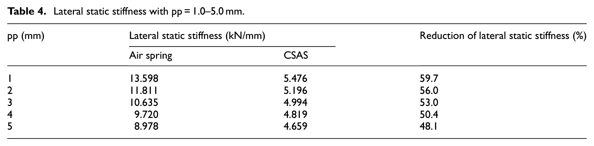
Figure 11 shows the static lateral to vertical stiffness ratio of the vibration isolators. It can be seen that after the hard elastic layer is connected in series, the stiffness ratio of the air spring drops from about 2.1 to about 1.3, when pp = 1.0 mm, the stiffness ratio is reduced from 2.14 to 1.25.

Static lateral to vertical stiffness ratio of the vibration isolators.
In this section, static characteristics tests of the vibration isolators are carried out, including air pressure-load test, vertical and lateral static stiffness tests. The static stiffness of the vibration isolators is obtained by fitting the displacement-load curves with polynomial fitting method. The test results show that the decrease of the load-carrying capacity of the CSAS is caused by the compression deformation of the hard elastic layer; compared with the air spring, the vertical static stiffness of the CSAS is slightly reduced under different pp values, while the lateral static stiffness and the static lateral to vertical stiffness ratio are greatly reduced under different pp values.
Dynamic characteristics tests of the CSAS
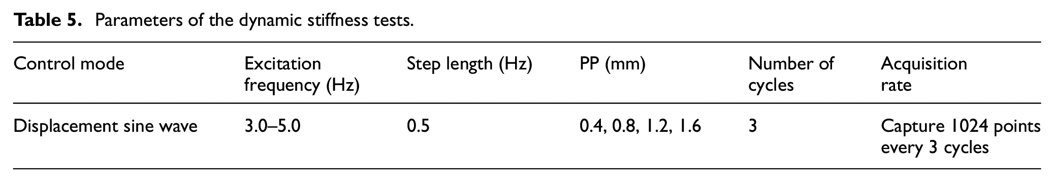
The test equipment and vibration isolator installation method for the dynamic stiffness tests are the same as those for the static stiffness tests. In order to reduce the number of disassembly and installation of the test device, the vertical and lateral dynamic stiffness tests can be conducted after the static stiffness tests, and simple harmonic excitation is applied to the vibration isolator. It is expected that the excitation frequency range can include the natural frequency of the vibration isolator, so as to obtain the most realistic result of the dynamic stiffness of the vibration isolator. Through theoretical estimation, it is concluded that the natural frequency of the vibration isolator is roughly in the frequency range of 3.0–5.0 Hz, so this frequency range is selected as the excitation frequency, the step length is 0.5 Hz. At each excitation frequency, the excitation peak-to-peak (referred to as PP) values are set as 0.4 mm, 0.8 mm, 1.2 mm, and 1.6 mm.
Table 5 shows the relevant parameters of the dynamic stiffness tests.
Parameters of the dynamic stiffness tests.
Vertical dynamic stiffness test
Generally, the stiffness value when the natural frequency of the vibration isolator is closest to the excitation frequency is taken as its vertical dynamic stiffness, this is because when the excitation frequency is close to the natural frequency, it is easier to excite the vibration isolator, and the result of dynamic stiffness is also closer to the actual situation. Calculate the vertical dynamic stiffness under different PP values, as shown in the Table 6.
Vertical dynamic stiffness and natural frequency under different PP values.

It can be seen from Table 6 that the vertical dynamic stiffness of the air spring is further reduced after the hard elastic layer is connected in series. When PP = 0.4 mm, 0.8 mm, 1.2 mm, and 1.6 mm, the vertical dynamic stiffness of the CSAS is reduced by 21.0%, 21.2%, 21.7%, and 21.8%, respectively. Normally, the test result corresponding to PP = 0.4 mm is used as the dynamic stiffness of the vibration isolator. When the excitation frequency is 5.0 Hz, the vertical dynamic stiffness of the air spring is 7.81 kN/mm, and its natural frequency is 4.97 Hz; when the excitation frequency is 4.5 Hz, the vertical dynamic stiffness of the CSAS is 6.17 kN/mm, and its natural frequency is 4.42 Hz. After the hard elastic layer is connected in series, the vertical natural frequency of the air spring is reduced by 0.55 Hz.
Lateral dynamic stiffness test
When calculating the lateral dynamic stiffness, the selected excitation frequency should correspond to the vertical direction. Table 7 shows the lateral dynamic stiffness of the air spring and the CSAS.
Lateral dynamic stiffness under different PP values.
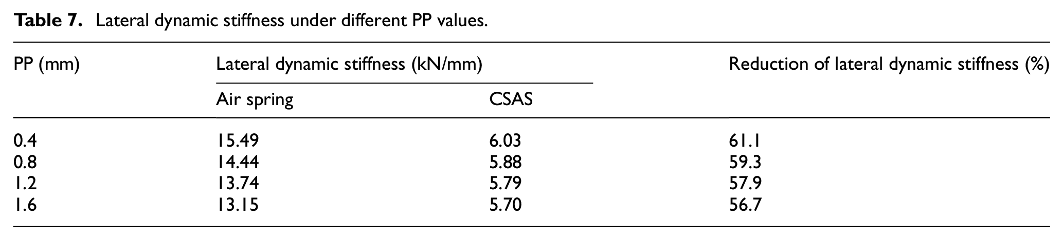
It can be seen from Table 7 that the lateral dynamic stiffness of the air spring is greatly reduced after the hard elastic layer is connected in series. When PP = 0.4 mm, 0.8 mm, 1.2 mm, and 1.6 mm, the lateral dynamic stiffness of the CSAS is reduced by 61.1%, 59.3%, 57.9%, and 56.7%, respectively. When PP = 0.4 mm and the excitation frequency is 5.0 Hz, the lateral dynamic stiffness of the air spring is 15.49 kN/mm; when the excitation frequency is 4.5 Hz, the lateral dynamic stiffness of the CSAS is 6.03 kN/mm. After the hard elastic layer is connected in series, the dynamic lateral to vertical stiffness ratio of the air spring is reduced from 1.98 to 0.98, and the lateral dynamic stiffness is reduced to a level equivalent to the vertical dynamic stiffness.
In this section, dynamic characteristic tests of the vibration isolators are carried out, including vertical dynamic stiffness test and lateral dynamic stiffness test. The results show that: compared with the air spring, the vertical dynamic stiffness of the CSAS is slightly reduced under different PP values, while the lateral dynamic stiffness and dynamic lateral to vertical stiffness ratio are significantly reduced; the natural frequency of the CSAS is slightly reduced, which has a positive impact on improving its vibration isolation capability.
Safety and reliability tests
Lateral shear test
The air spring will produce tangential deformation when the ship is subjected to the thrust of the propeller or when the attitude adjustment such as tilting and swinging is performed. To ensure the safety of the air spring, the tangential deformation is usually required to be no more than 5.0 mm. When large transverse shear deformation occurs, the vulcanized joint is a weak part, and the hard elastic layer may be torn or peeled under the action of shearing force. Therefore, a lateral shear test is required to ensure that the CSAS will not be damaged under large tangential deformation. The test method of the lateral shear test is the same as that of the lateral stiffness test, pp = 6.0–12.0 mm is controlled during the lateral shear test (the lateral static stiffness test has proved that the CSAS is safe and reliable in pp = 1.0–5.0 mm), the step length is 1.0 mm, and the loading speed is 0.1 mm/s. Figure 12 shows the results of the CSAS lateral shear test.

Lateral shear test.
It can be seen from Figure 12 that when pp = 6.0–12.0 mm, the lateral displacement-load curves are all smooth and closed hysteresis curves, which shows that under complex working conditions, the performance of the CSAS remains stable.
Vertical compression failure test
When the CSAS is subjected to large vertical compression load, the hard elastic layer may collapse, so it is necessary to carry out vertical compression failure test. Fix the CSAS at the rated height and slowly inflate the capsule to rated air pressure, apply pressure slowly until it reaches 5 times of the vertical rated load (i.e. 392 kN). Figure 13 shows the vertical compression failure test result.

Vertical compression failure test.
It can be seen from Figure 13 that the performance of the CSAS remains stable under a load and unload cycle. When the vertical displacement is about 0–10.0 mm, the load increases slowly with the displacement, and the stiffness of the CSAS does not change significantly. This is because under a small displacement, the limit seat in the capsule does not come into contact with the limit shaft, and the deformation is mainly caused by the rubber capsule and the hard elastic layer, while the rigidity of them is not large. When the displacement continues to increase beyond the limit gap, the limiter will work, and the rigidity of the limiting device is much greater than the rubber capsule and the hard elastic layer, so that the load increases significantly with the increase of the displacement in this process. When the vertical compression load reaches 392 kN, it will undergo a compression deformation of 14.38 mm.
During the unloading process, the location where the stiffness changes are basically the same as the loading process, but when the unloading is completed, the CSAS will not completely return to its original shape, but will produce a compression deformation of about 1.0 mm, which is due to the cohesion of the rubber material cannot be eliminated when under great pressure, and it will produce extremely unstable contraction, which takes a period of time to recover.
Vertical tensile failure test
When the CSAS is subjected to large vertical tensile load, the hard elastic layer may be pulled off, so it is necessary to carry out the vertical tensile failure test. Before the test, empty the air in the capsule, and fix it on the testing machine at a rated height. Apply vertical tension to the CSAS, slowly stretch the air spring until the limiting device works, then continue to slowly apply the tension until it reaches 5 times the vertical rated load. Figure 14 shows the result of the vertical tensile failure test.
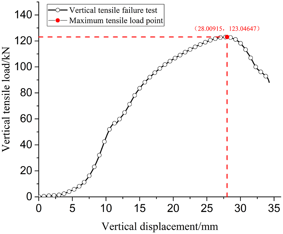
Vertical tensile failure test.
It can be seen from Figure 14 that when the vertical displacement is about 0–7.5 mm, the load increases slowly with the increase of the displacement, this is because the deformation is mainly the rubber capsule and the hard elastic layer in this process, and their stiffness are small. When the displacement is about 7.5–15.0 mm, the load increases obviously with the increase of the displacement, this is because the limit device works at this time, and its stiffness is great. When the displacement continues to increase, the load tends to slow down with the increase of the displacement. When the displacement reaches about 28.0 mm, the load reaches its maximum value, about 123.046 kN. After that, the tension continues to be applied and the load decreases sharply.
There are mainly two possible reasons for the sudden drop. One is that the hard elastic layer is damaged, peeling off from the air spring; the other is that the limiter is severely deformed, and the restricting effect is completely lost. After disassembling the CSAS, it is found that the hard elastic layer remains intact, but the limiter has undergone severe bending deformation, which directly leads to the sudden change of the vertical tension, as shown in Figure 15. Generally, the limiter can usually meet the requirements of various harsh working conditions, and the hard elastic layer remains intact when the limiter is damaged, which shows that the CSAS is safe and reliable when subjected to a large vertical tension.
Bending of the limiter.
Fatigue tests
The vertical and lateral fatigue tests were carried out. In the fatigue tests, the CSAS is fixed at a rated height and then inflated to the rated air pressure. Sinusoidal excitation is applied to the CSAS, the excitation amplitude, excitation frequency, and number of excitation cycles can be set in the computer control system. When the set number of cycles is reached, the sinusoidal excitation will automatically stop. According to the fatigue test standard of vibration isolator, during the vertical fatigue test, the bearing capacity of the CSAS is controlled as the rated working load, the excitation amplitude is ±1.27 mm, the excitation frequency is set to the vertical natural frequency of the CSAS, and the vertical vibration is conducted for 10,00,000 cycles; during the lateral fatigue test, the excitation amplitude is ± 1.27 mm, the excitation frequency is set to the lateral natural frequency of the CSAS, and the lateral vibration is carried out for 10,00,000 cycles, too. After the fatigue tests, the performance of the CSAS remains stable.
In this section, the reliability tests and safety verification of the CSAS are carried out. After the lateral shear test, the vertical compression failure test, the vertical tensile failure test, and the fatigue tests, it was observed that the hard elastic layer did not fall off or damage. The structure of the CSAS remains intact and the performance of the CSAS remains stable, indicating that it can meet the requirements under complex and harsh conditions.
Conclusion
In this paper, a CSAS is proposed. By connecting a hard elastic layer at the lower end of the air spring, the vertical stiffness of the air spring can be reduced slightly, and the lateral stiffness can be greatly reduced, this will have a positive effect on improving the vibration isolation ability.
Prototypes of the air spring and the CSAS with a rated load of 8t were produced, then related tests were carried out, the following conclusions can be drawn:
The linear relationship between the air pressure and the bearing capacity does not change after the hard elastic layer is connected in series, but the bearing capacity of the air spring will decrease slightly, and the rated air pressure of the CSAS increases by 0.1 MPa than that of the air spring. This is due to the compression deformation of the hard elastic layer, which increases the height of the air spring body and reduces its effective radius. The hardness of the hard elastic layer can be appropriately increased to improve the bearing capacity.
After the hard elastic layer is connected in series, the vertical static stiffness of the air spring is further reduced, and the lateral static stiffness is greatly reduced. The static lateral to vertical stiffness ratio of the air spring is reduced from about 2.1 to about 1.3. When pp = 1.0 mm, the vertical and lateral static stiffness decreases by 31.0% and 59.7%, respectively, and the ratio of lateral to vertical static stiffness is decreased from 2.14 to 1.25.
After the hard elastic layer is connected in series, the vertical dynamic stiffness of the air spring is further reduced, and the lateral dynamic stiffness is greatly reduced. When PP = 0.4 mm, the vertical dynamic stiffness decreases by 21.0%, the natural frequency decreases by 0.55 Hz, the lateral dynamic stiffness decreases by 61.1%, and the ratio of lateral to vertical dynamic stiffness is reduced from 1.98 to 0.98.
The CSAS was tested by the lateral shear test, the vertical compression failure test, the vertical tensile failure test and the fatigue tests. Its performance was stable without damage, indicating that it is safe and reliable.
Combined with the work that has been carried out in this article, the following studies can be carried out in depth:
(i) Carry out the vibration transmission characteristics test of the CSAS, build the test bench of ship floating raft vibration isolation system, explore the vibration isolation ability of the CSAS in different frequency bands; (ii) Produce the CSAS with different thickness, hardness and Young’s modulus, Explore the influence of the parameter characteristics of the hard elastic layer on the performance characteristics of the CSAS.
Footnotes
Handling Editor: James Baldwin
Declaration of conflicting interests
The author(s) declared no potential conflicts of interest with respect to the research, authorship, and/or publication of this article.
Funding
The author(s) disclosed receipt of the following financial support for the research, authorship, and/or publication of this article: This work was supported by the Key Laboratory Fund (number: 9140C280301).
Availability of data
The data that support the findings of this study are available from the corresponding author upon reasonable request.