
Abstract
In order to study the rubbing of the mistuned bladed disk system with variable thickness blades, an elastically supported shaft-variable thickness blades coupled finite element model is established in this paper. A new rubbing force model is proposed considering the variable thickness section characteristics and rotation effect of the variable thickness blade. A method of mistuned parameter identification is introduced which consists of static frequency testing of blades, dichotomy, and finite element analysis. Based on the finite element method, the mistuned bladed disk system is made dynamic analysis in full rubbing by applying the judgment load method. The dynamic response of the mistuned bladed disk system is discussed under different conditions. The results show that increasing the amount of mistuning will increase the system vibration. At high speeds, the impact force will be partially offset by centrifugal force. And the rubbing gap affects the form of rubbing. With the gap decreases, the system will change from intermittent rubbing to continuous rubbing. In addition, when the system is rubbed, due to energy dissipation and blade damping, the stress is transferred from the blade tip to the blade root and attenuated. In general, rubbing is a random complex nonlinear vibration process.
Keywords
Introduction
In engineering practice, in order to improve the performance and efficiency of the aero-engine rotor system, slight gap between the blade and casing is adopted in general. However, due to manufacturing and processing errors, detuning, eccentricity and other factors, the high-speed rotor system will produce large vibrations. When the radial displacement of the blade is greater than the gap between the blade and the casing, the system will encounter rubbing, which usually induce damage of blades and casing or generate complex vibration of rotor system. And it may lead to reduce system performance. Therefore, it is of great significance to study rubbing on the rotor system.
For many studies involving rotor-blade rubbing, countless researchers have carried out a lot of studies on this research topic and have obtained fruitful results. Ma et al. 1 simulated two types of blade-tip rubbing due to the static misalignment of the bladed-disk center and casing center and casing deformation and analyzed vibration responses due to blade–casing rubbing under the run-up process with constant angular acceleration and the steady-state process by applying aerodynamic load in the blade lateral/flexural direction. Kou and Yuan 2 examined rub-induced non-linear responses of a rotating large deflection plate and obtained bifurcation and chaos showing a rich and complex behavior in tip-rub. Sun et al. 3 developed finite element model of a rotating blade with variable-thickness and compared vibration responses using varying-thickness-twisted shell and solid element finite element models. In order to investigate speed transients with rotor-to-stator rubbing caused by an accidental blade-off imbalance, Roques et al. 4 introduced a rotor–stator model of a turbogenerator. Yang et al. 5 investigated rub-impact mechanism with surface coatings and discussed effects of eccentricity of disk, surface coatings and radius of shaft. Behzad et al. 6 developed an algorithm for more realistic investigation of rotor-to-stator rubbing vibration based on finite element theory with unilateral contact and friction conditions. Cao et al. 7 proposed a novel hysteretic force model to describe the contact force of the rotor blade and casing. Mandard et al. 8 presented an experimental methodology to estimate the blade–seal interacting force from indirect measurements. Legrand et al. 9 proposed a strategy for the numerical investigation of blade/casing interaction through direct contact. Peletan et al. 10 developed a quasi-periodic harmonic balance method coupled with a pseudo arc-length continuation algorithm and used for the prediction of the steady-state dynamic behaviour of rotor–stator contact problems. Batailly et al.11,12 developed a blade–casing rubbing model considering the effects of the material removal based on a piecewise linear plastic constitutive law. Taking into account different contact positions in the width direction, Yuan et al. 13 developed a contact-impact model for the rub-induced vibration analysis of a rotating geometric nonlinear plate under thermal shock. Li et al.14,15 deduced an improved rotating blade–casing rubbing model based on elastic compatibility conditions, which considered Influences of rigid and flexible casing displacements. Chen 16 carried out a lot of blade–casing rubbing experiments and analyzed the casing vibration acceleration signals in order to extract the rubbing faults’ characteristics. Lu et al. 17 established the radial-torsional coupling model of the rub rotor in polar coordinate system considering the influence of speed whirling and analyzed the dynamics characteristics under no rub, full annual rub and partial rub conditions. Patel et al. 18 presented a mathematical model consisting of interacting vibratory systems of rotor and stator and modeled the contact using contact stiffness, damping and Coulomb friction. Sun et al. 19 investigated the steady-state responses and their stability of a dual-rotor system with rub-impact. Using a lumped mass model of a single rub-impact rotor system, Tai et al. 20 investigated the stability and steady-state response of the rotor system. Wu et al. 21 built up the simplification model of the turbine rotor and computed the contact stress of turbine rotor. Padova et al. 22 described experimental results obtained for an Inconel compressor blade rubbing a steel casing at engine speed. Mokhtar et al. 23 investigated the rotor stator interaction phenomenon in the finite element frame work using Lagrange multiplier based contact mechanics approach.
After this introduction, in this paper, an elastically supported shaft-variable thickness blades coupled finite element model is established. And taking into account the variable thickness section characteristics and rotation effect of the variable thickness blade, a new blade and casing rubbing force model is proposed. On the basis of the finite element method, the dynamic analysis of the mistuned bladed disk system is carried out by using the judgment load method, and the dynamic response of the system is discussed under various conditions.
Establishment of the whole equivalent mistuned bladed disk model
Establishment of finite element model
The solid model of mistuned bladed disk studied in this paper which is shown in Figure 1, consists of a disk and 38 variable thickness blades. The disk has a diameter of 460 mm and a thickness of 47 mm, the variable thickness blade has a length of about 75 mm and a twist angle of about 30°.

The mistuned bladed disk solid model.
In order to improve calculation efficiency and reduce storage space, the disk is simplified to a concentrated mass point centered at the center of the rotating shaft (coincident with the center of the disc), the Mass21 element is used for simulation; the total length of the rotating shaft is 1000 mm. It is equally divided into 50 Timoshenko beam elements and simulated by Beam188 element. Both ends of the rotating shaft use spring-damping elements in two radial directions to simulate elastic support, and the spring-damping element is simulated with Combine14 element whose stiffness and damping are respectively 1.5 × 10⁷ N/m, 1000 (N s)/m; the blades are meshed by solid elements, and the axis node takes the rigid connection with all the blade root nodes, as is shown in Figure 2.

Finite element model of the mistuned bladed disk.
The material used for the variable thickness blades in the simplified finite element model is titanium alloy. At present, Ti6Al4V and Ti6Al2Sn4Zr2Mo are the most commonly used titanium alloys for rotating blades in aviation. Compared with other commonly used metal materials, it has the advantages of low density, good mechanical properties, good toughness, high strength, good corrosion resistance, good creep resistance, good fatigue resistance, low linear expansion coefficient and low thermal conductivity. The shaft is made of steel. The specific parameters are shown in Table 1, where ρ is the density of the material, E is the elastic modulus of the material, and μ is the Poisson’s ratio of the material.
Material parameters of disk rotor system.

Modal analysis of finite element model
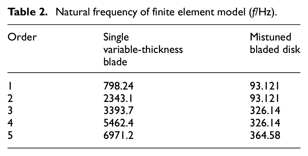
In order to verify the correctness of the finite element model, the modal analysis of a single variable-thickness blade and the mistuned bladed disk are performed, and the natural frequencies obtained are as follows, see Table 2.
Natural frequency of finite element model (f/Hz).
Dynamic analysis of the mistuned bladed disk system
Rubbing force model of variable thickness curved blade
The dynamic equation of the rubbing system is as follows:

where M, C, and K are the mass matrix, damping matrix, and stiffness matrix of the system; B is the rotational softening matrix caused by the rotation of the rotor system. It reduces the stiffness of the system, F is the rubbing load vector of the blade.
When the blade and the casing are rubbed, the interaction between the blade and the casing is usually a piecewise linear spring model. If the rubbing occurs, the deformation of the contact surface of the casing is δ. The most common linear normal frictional force formula is:

where k is the stiffness coefficient of the contact surface of the casing.
Padovan et al. 24 assumed that the blade is a cantilever beam and derives a new frictional force model by energy method. Ma et al. 25 deduced a nonlinear normal rubbing force model for straight or cone-plate blades (the rectangular cross section of the blade changes uniformly along the length and width directions) considering the rotation effect of the blade and the elastic effect of the casing.
However, for a variable thickness curved blade, the blade root section is not rectangular, but approximates the crescent shape as shown in Figure 3. If the section is treated as a rectangle, the accuracy of the calculation result will be affected. Here the blade root shape is simplified to the crescent shape where the two circles intersect as shown in the shaded part of Figure 4. Considering the bending deformation and rotation effect of the blade, regardless of the axial compression and thermal effects of the blade rubbing, the radial rubbing force model is established based on a contact process. The rubbing diagram is shown in Figure 5.

Variable thickness torsion blade.

Blade root cross section simplified diagram.
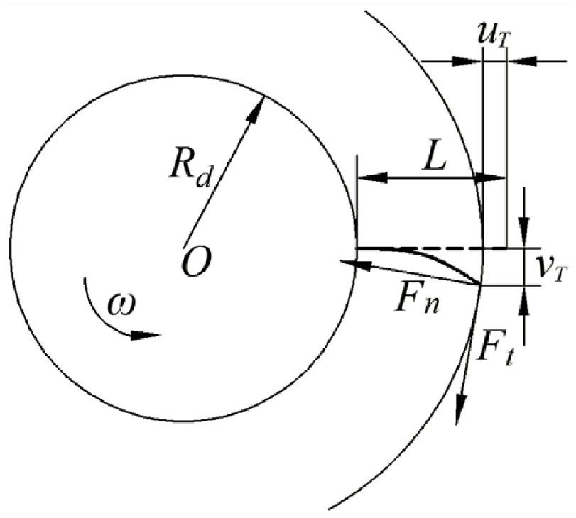
Blade and casing rubbing diagram.
Define the blade cross-sectional area and the section moment of inertia to satisfy the following relationship:


where τα is the circumferential taper ratio, τα = 1 − (α3+α4)/(α1+α2), α1, α2, α3, and α4 are the inner arc angle of the blade root, the outer arc angle of the blade root, the inner arc angle of the blade tip, and the outer arc angle of the blade tip, τR is the radial taper ratio, τR = 1 − (R3 + R4)/(R1 + R2). R1, R2, R3, and R4 are inner radius of blade root, the outer radius of blade root, inner radius of blade tip, and the outer radius of blade tip. A0 and I0 are the blade root cross-sectional area and the blade root section moment of inertia. The expression is
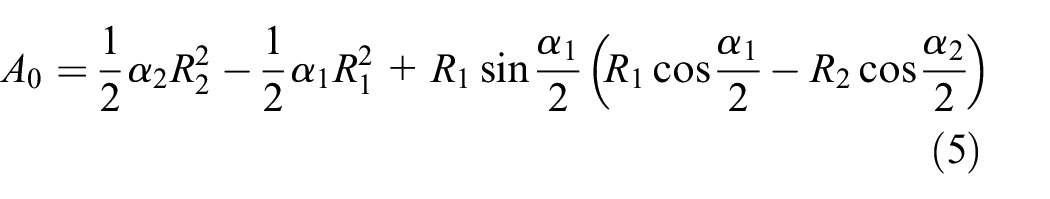

where h is the distance of O1O2,
According to the knowledge of material mechanics, the deformation amount v of the cantilever beam can be expressed as25,26
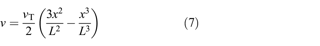
where vT is the tangential displacement of the blade tip. The potential energy of the blade in the occurrence of rubbing is mainly the bending potential energy VB and the centrifugal potential energy VC, the expressions are respectively


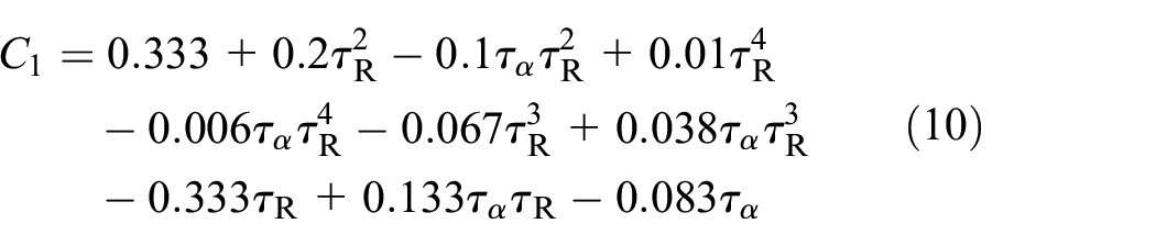
where the expression of C1 is
The total work W made by the blade in the event of rubbing includes the work of the normal rubbing force FN and the tangential rubbing force Ft. The friction model is described by Coulomb friction, that is, Ft = μFN, μ is the coefficient of friction. The expression of the total work W is

where uT is the normal displacement of the blade tip and its expression is

According to the law of conservation of energy, it can be obtained as

Substituting equations (7), (8), and (10) into equation (13), it can be obtained as
After simplification, the tangential displacement expression of tip can be obtained as

where

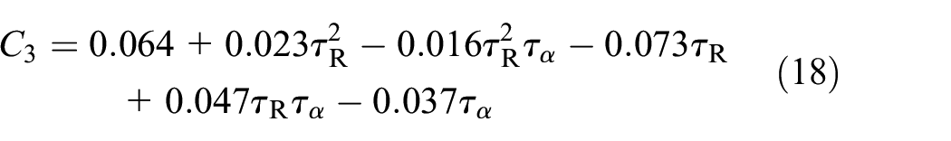
where ρ is the blade density, ω is the blade rotation speed, and Rd is the disk radius. The expressions of C2 and C3 are

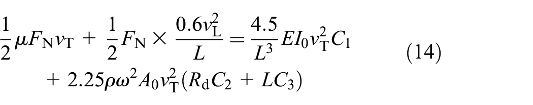
Substituting equation (14) into equation (12), it can be obtained as

And the amount of blade intrusion is equal to the normal displacement of the blade tip, that is, δ = uT. Substituting equation (18) into equation (11), it can be obtained as

The tangential impact force Ft is

The total impact force F is the vector sum of the tangential impact force and the normal impact force, which can be expressed as

Dynamic analysis process
In the article, in order to simulate blade–casing rubbing phenomenon, the method that the rubbing load is applied to the blade tip is used. Whether the blade–casing impact is rubbed or not is determined by normal displacement of blade tip and radial distance between blade tips and inner wall of casing. If normal displacement of tip is more than radial distance between tips and inner wall of casing, normal rubbing force and tangential rubbing force are applied at the blade tip; If the normal displacement of blade tips is less than the radial distance between tip and inner wall of casing, no rubbing occurs. Therefore, applying this kind of judgment load to each blade to achieve the purpose of simulating the entire system. The flow chart is shown in Figure 6.
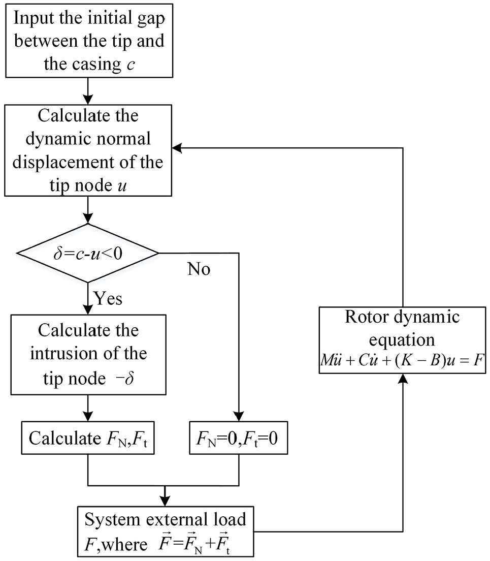
Blade–casing rubbing simulation process flow chart.
Mistuned parameter identification method
The blade-disk structure system is a harmonic periodic structure whose mode shape is uniformly transmitted to the entire structure in the circumferential direction. However, in fact, factors, such as hand manufacturing, materials, and wear and tear often lead to structural parameters, such as shape, stiffness, and mass of the blade that are not exactly the same along the circumferential direction of the disk. This blade-disk structure is called a mistuned structure. In engineering practice, the frequency modulation of the blades and the control of the frequency dispersion of the blades are generally adopted to prevent the blade fluttering fault. However, in the finite element simulation, it is difficult to introduce the mistuning caused by the difference of the blade frequency in the engineering practice. This section mainly transforms the mistuning of the blade frequency into the mistuning of the elastic modulus in the finite element model.
Assuming that the disk is tuned, only the variation of the blade parameters is considered, and the mistuning is simulated by introducing different mistuning parameters for the elastic modulus of each blade.

where Pj is the mistuning parameter, which contains the elastic equivalent of these mistuning, so that the mistuning of each sector of the structure can be quantitatively compared.
In this section, a method based on blade static frequency test, dichotomy, and finite element analysis is used to identify the mistuning parameter Pj. Firstly, the static frequency test is carried out on each blade of a compressor blade system, and the first-order bending static frequency of each blade is obtained through the test information acquisition and analysis system. Secondly, by introducing different disturbance parameters to the elastic modulus of each blade of the blade disk system, the variation of the blade frequency is simulated. Assuming that the disk is harmonized, only the blade material parameter changes are considered, and the blade elastic modulus disturbance parameter is the mistuning parameter. The combination of dichotomy and finite element analysis is used to identify the mistuning disturbance parameters and the mistuned elastic modulus corresponding to the first-order bending natural frequency of the blade static frequency test. Finally, the mistuned elastic modulus of each blade necessary for the analysis of the vibration and dynamic characteristics of the blade disk system is obtained by fitting calculation.
The basic process of blade mismatch parameter identification based on blade static frequency test, dichotomy, and finite element method is shown in Figure 7. The blade mismatch parameter identification scheme based on blade static frequency test, dichotomy, and finite element method is as follows:
(1) Set up the blade static frequency test device to test the bending frequency of each stationary blade
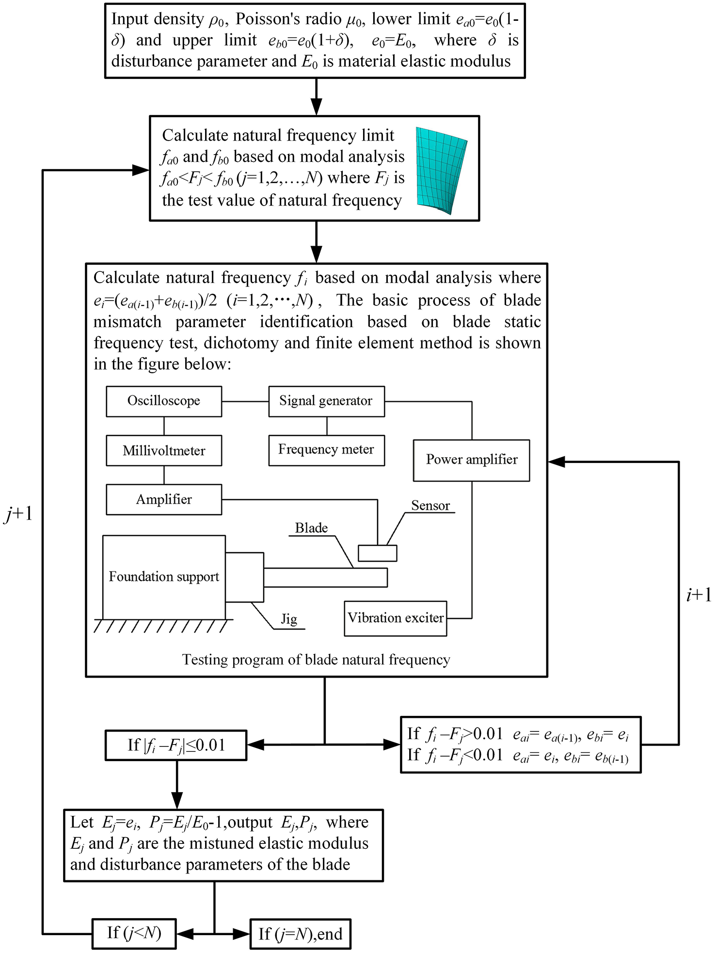
Flow diagram of blade mistuned parameter identification.
The resonance method is used to measure the blade static frequency. That is, when the blade is under the action of the exciting force, the frequency of the force is equal to the natural vibration frequency of the blade and its position and phase are appropriate, the blade enters the resonance state by the forced vibration. The natural frequency of the blade can be obtained by measuring the frequency of the exciting force.
(2) The finite element model of the blade is established. According to the elastic modulus parameter of the blade material, the upper and lower limits of the mistuned elastic modulus are given, and the modal analysis is performed on the single blade by the finite element method. The boundary condition is set to the full displacement of the three directions of each node of the blade-to-disk interface.
(3) First, calculate the first order bending natural frequency of the blade corresponding to the upper and lower limits of the elastic modulus. Then, calculate the first order bending static frequency and compare the results of the test and the finite element method. The convergence criterion is defined as the error being less than 0.01. Finally, state the mistuning elastic modulus which corresponds to the test.
Results and discussion
In order to better reflect the law of rubbing in the blade-rotor system, in this section, the stress changes on the blade during rubbing are analyzed.
The stress distribution on the mistuned bladed disk is shown in Figure 8(a) when the second rubbing occurs (3.855 s). It can be observed that the stress at the tip of the blade is maximum at this time. However, after 0.015 s, due to the action of the stress wave as shown in Figure 8(b), the stress is gradually transmitted to the blade root. During the process of stress conduction, there is energy dissipation and stress attenuation, which is caused by material damping and energy dissipation.
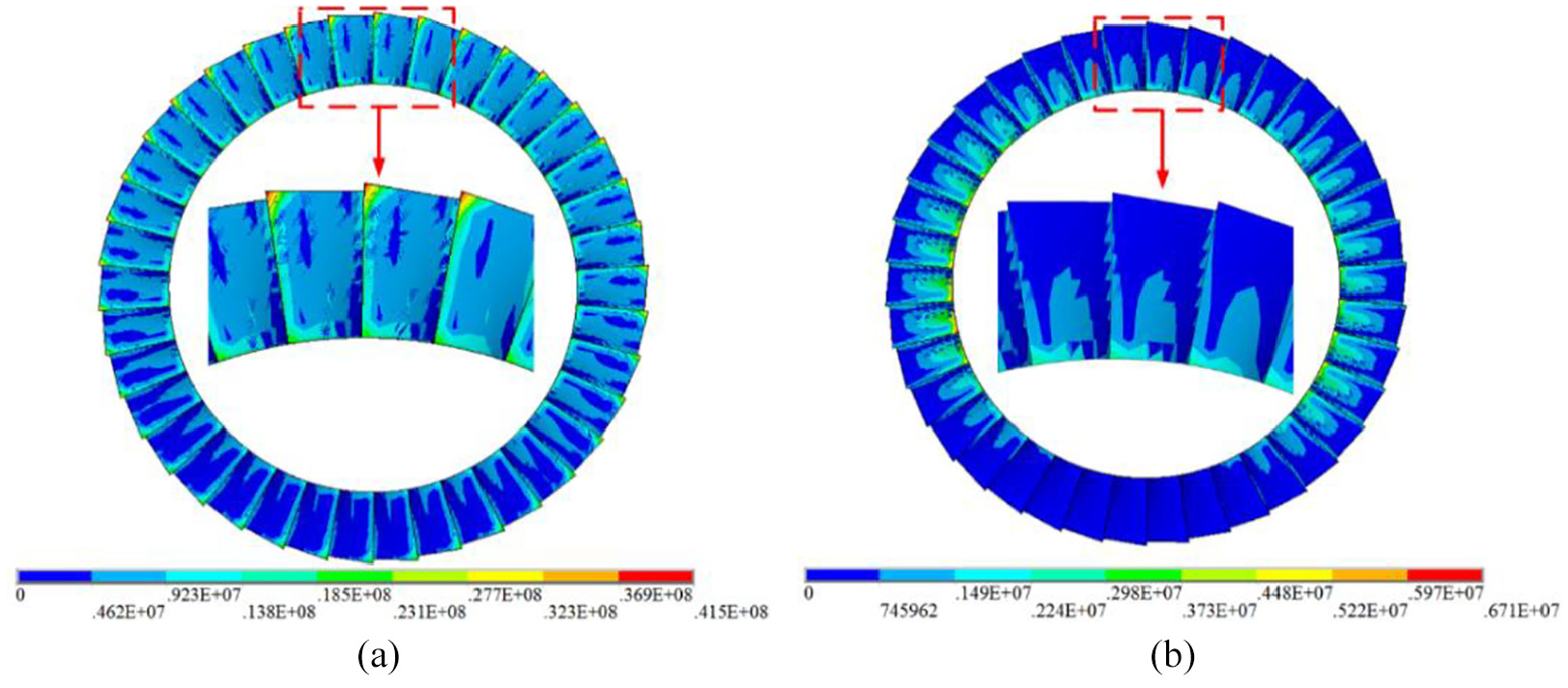
Blade stress distribution diagram: (a) 3.855 s and (b) 3.87 s.
Influence of mistuning standard deviation
In this section, the influence of standard deviation of mistuned blade on vibration responses of the mistuned bladed disk are analyzed under the rubbing conditions with 5 × 10⁻⁵ m rubbing gap and the rotation speed is 10,000 rpm. The vibration responses of the mistuned bladed disk are evaluated respectively.
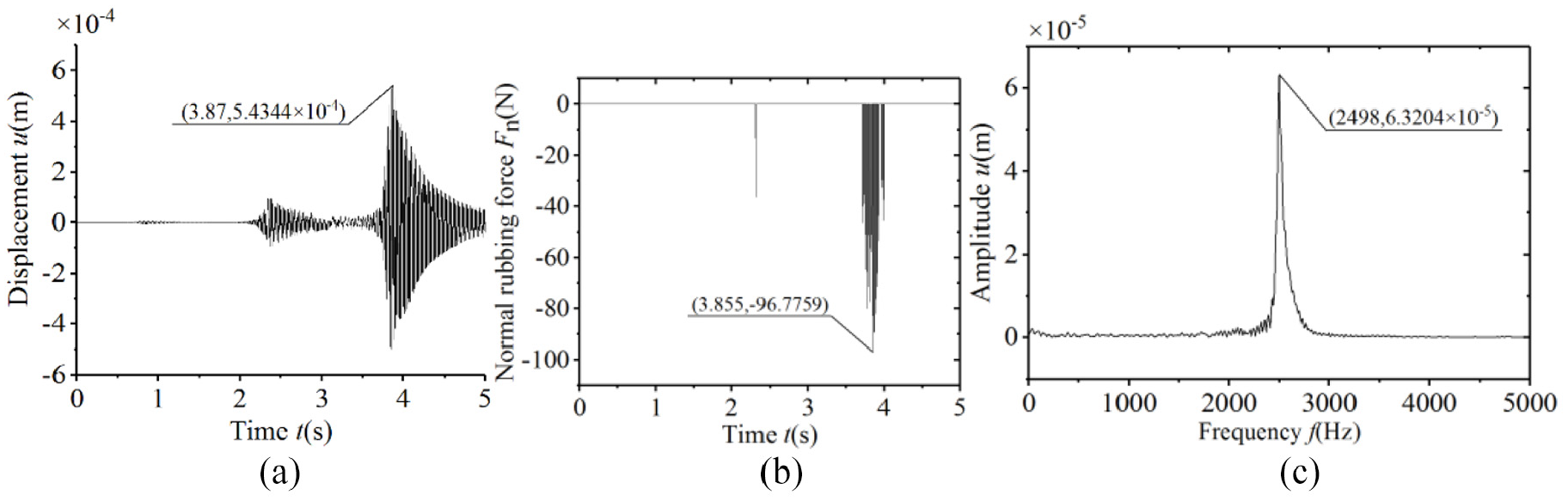
Under different standard deviation of mistuned blade (0%, 1%, 3%, and 5%), the blade vibration responses are shown in Figures 9 to 12. In the figures, the time-domain waveform show that the mistuned bladed disk system generates normal displacements excited by centrifugal force and rubbing loads. Multiple dynamic phenomenons indicate that the system has two rubbings during the process of increasing the speed increase, and the rubbing is more severe with the time increases. Comparing the four sets of data, it is clear that the curve shapes are roughly similar, but there are slight deviations. With the standard deviation of the elastic modulus of the blade increases, the maximum radial displacement of the blade tip and the maximum radial rubbing force will increase slightly. This is because the increase of the mistuning will aggravate the destruction of the symmetry of the blade. The degree of localized vibration of the entire system will increase accordingly. From the amplitude-frequency curve, it can be observed that there is obvious amplitude amplification at 2498 Hz, which is the high-frequency component aroused by the blade in the rubbing process.

The vibration response of the tuned bladed disk: (a) time domain waveform, (b) normal rubbing force, and (c) spectrogram.
The vibration response of standard deviation of 1% of mistuned bladed disk: (a) time domain waveform, (b) normal rubbing force, and (c) spectrogram.

The vibration response of standard deviation of 3% of mistuned bladed disk: (a) time domain waveform, (b) normal rubbing force, and (c) spectrogram.

The vibration response of standard deviation of 5% of mistuned bladed disk: (a) time domain waveform, (b) normal rubbing force, and (c) spectrogram.
Influence of rotational speed
In this section, the rubbing response is reflected by different changing interval of the rotational speed in 5 s under rubbing conditions with 5 × 10⁻⁵ m rubbing gap and 1% standard deviation of mistuned blade, and the vibration responses of the mistuned bladed disk are analyzed respectively.
Under different changing interval of the rotational speed (10,000, 15,000, 20,000, and 5000 rpm), the blade vibration responses are shown in Figures 13 to 16. It can be observed that within 5 s, with the rotation speed increases, the number of resonance peaks of the radial displacement of the blade tip will increase, and the maximum radial displacement and the maximum radial rubbing force of the blade tip will also increase accordingly. At low speeds, the peak radial displacement of the blade tip at each resonance will increase in turn with the increase of time. However, under the condition of high speed, with the increase of time, each peak of the radial displacement of the blade tip will not always increase, and the rubbing force will increase with the increase of time. This phenomenon is because the normal rubbing force is partially offset by the centrifugal force.

The vibration response at the speed of 10,000 rpm: (a) time domain waveform, (b) normal rubbing force (c) spectrogram.

The vibration response at the speed of 15,000 rpm: (a) time domain waveform, (b) normal rubbing force, and (c) spectrogram.

The vibration response at the speed of 20,000 rpm: (a) time domain waveform, (b) normal rubbing force, and (c) spectrogram.

The vibration response at the speed of 25,000 rpm: (a) time domain waveform, (b) normal rubbing force, and (c) spectrogram.
The stress distribution of blades is shown in Figure 17 under different rotational speed when the blade rubbing force is maximum respectively. It can be seen from the figure that the maximum stress on the blade increases and the blade rubs more severely in high speed. It can be observed on the surface of the blade that the minimum stress area appears at the middle of the blades.
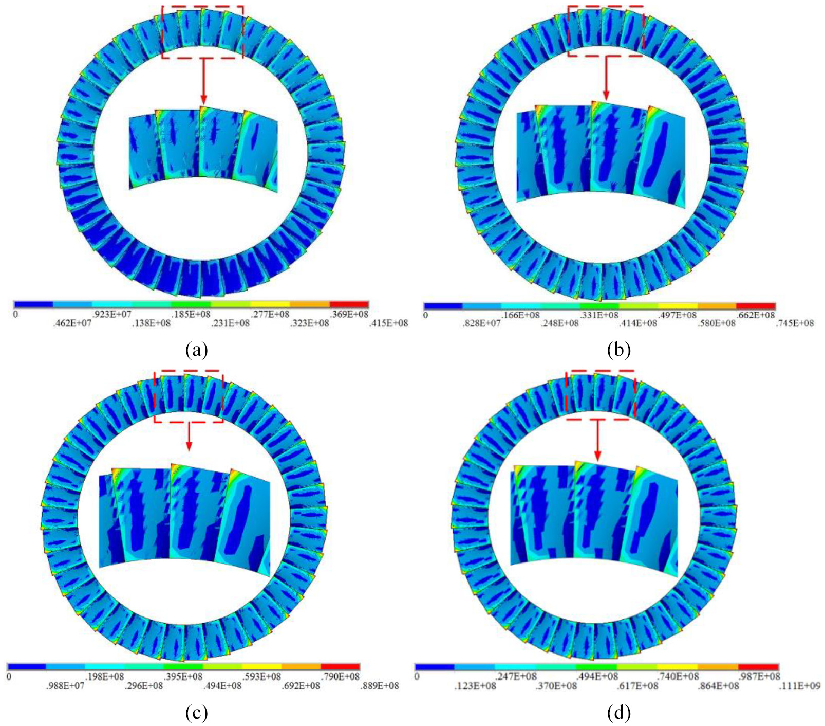
Stress distribution diagram of system rubbing at different rotational speed: (a) 10,000 rpm, (b) 15,000 rpm, (c) 20,000 rpm, and (d) 25,000 rpm.
Influence of rubbing gaps
In this section, considering the effect of Coriolis force, the influence of rubbing gaps on vibration response of the mistuned bladed disk structure is studied under rubbing conditions with 1% standard deviation of mistuned blade and the rotation speed is 10,000 rpm, and the vibration responses of the mistuned bladed disk are analyzed respectively.
Under different rubbing gaps (1 × 10⁻⁵, 3 × 10⁻⁵, 5 × 10⁻⁵, and 7 × 10⁻⁵ m, repectively), the blade vibration responses are shown in Figures 18 to 21. When the rubbing gap is large, it can be observed that the interval between two adjacent rubbings is longer, which means that the system will intermittently rubbing. With the rub-impact gap decreases, the system gradually changes from intermittent rub-impact to continuous rub-impact, and the maximum normal rub-impact force will increase. This is because reducing the rub-impact gap will increase the amount of blade intrusion. The spectrogram shows that with the rubbing gap decreases, the rubbing of the blade will arouse more high frequency components.

The vibration response under the rubbing gap of 1 × 10⁻⁵ m: (a) time domain waveform, (b) normal rubbing force, and (c) spectrogram.

The vibration response under the rubbing gap of 3 × 10⁻⁵ m: (a) time domain waveform, (b) normal rubbing force, and (c) spectrogram.

The vibration response under the rubbing gap of 5 × 10⁻⁵ m: (a) time domain waveform, (b) normal rubbing force, and (c) spectrogram.

The vibration response under the rubbing gap of 7 × 10⁻⁵ m: (a) time domain waveform, (b) normal rubbing force, and (c) spectrogram.
The stress distribution of blades is shown in Figure 22 under different rubbing gaps when the blade rubbing force is maximum respectively. It can also be observed on the surface of the blade that the minimum stress area appears at the middle of the blades. With the rubbing gaps decreasing, the maximum stress on the blade increases.

Stress distribution diagram of system rubbing under different rubbing gaps: (a) 1 × 10⁻⁵ m, (b) 3 × 10⁻⁵ m, (c) 5 × 10⁻⁵ m, and (d) 7 × 10⁻⁵ m.
Conclusion
In this study, a new rubbing model between the rotating variable thickness blade and casing is derived based on the law of conservation of energy, which takes into account variable thickness section characteristics and rotation effect of the variable thickness blade. Under the finite element software, an elastically supported shaft-variable thickness blades coupled finite element model is established. The dynamic characteristics of the misturned bladed disk system under blade–casing rubbing are studied and some conclusions that can be obtained are shown as follows:
Rubbing between the blades and the casing is a complex nonlinear vibration process, and the occurrence of rubbing is not continuous, but has a certain randomness.
When rubbing occurs, the maximum stress appears at the tip of the blade. After a period of time, the stress will gradually spread from the tip to the root and attenuate.
Increasing the standard deviation of the blade elastic modulus will result in a slight increase in the maximum radial displacement of the blade tip and the maximum radial friction force. With the rotation speed increases, the number of resonance peaks of the radial displacement curve of the blade tip increases. The reduction of the rub-impact gap will make the mistuned blade-disk gradually change from intermittent rub-impact to continuous rub-impact, and the maximum normal rub-impact force increases.
Footnotes
Handling Editor: James Baldwin
Declaration of conflicting interests
The author(s) declared no potential conflicts of interest with respect to the research, authorship, and/or publication of this article.
Funding
The author(s) disclosed receipt of the following financial support for the research, authorship, and/or publication of this article: This project is supported by the National Science Foundation of China (Nos. 51805076, 51775093, and U170 8255), the Postdoctoral Research Foundation of China (No. 2019M651147), the Fundamental Research Funds for the Central Universities (No. N170503011), and the Natural Science Foundation of Liaoning Province, China (No. 20180551058).