
Abstract
The present paper describes the formulation of a new moderately thick plate bending triangular finite element based on Mindlin–Reissner plate theory. It is called a Great Triangular Moderately Thick Plate Finite Element, or GTMTPFE. The formulation is based on the strain approach, on solution of Airy’s function and on the analytical integration in the construction of the stiffness matrix. The strengths associated with this approach consist of:
• automatic verification of equilibrium conditions and kinematic compatibility conditions,
• the enrichment of the degrees of the interpolation polynomials of displacements, strains and constraints (refinement p),
• the consideration distortions sections related to Poisson effects,
• the treatment of blocking phenomena related to transverse shear.
In general, this approach results in a competitive, robust and efficient new moderately thick plate finite element. This is visible, on the one hand, through its stability against patch tests (constant twists, state of constants moments, transverse shear locking phenomenon, isotropy test). This is visible, through its good response to the patch tests to which it is subjected (constant torsions, state of constant moments, phenomenon of blocking in transverse shears, isotropy test). As has excellent convergence to the reference solution. Thus, it exhibits better performance behavior than other existing plate elements in the literature, particularly for moderately thick plates and for thin plates (L/h ratio greater than 4).
Introduction
In the civil engineering field, it is often necessary to calculate shell-type structures that can be relatively complex (caisson decks, slabs, dams, vaults, etc.). For such structures, it is very unusual for classical theories of plates and shells to give analytical solutions to the problem directly. Therefore, most of the time, the use of numerical methods such as finite element methods, is necessary. Beam finite elements often provide a first approximation of the behavior of many simple structures, but they prove to be inadequate for the study of more complex works. In these latter cases, it is necessary to use more efficient elements such as shell finite elements or three-dimensional finite elements. A brief non-exhaustive review of the literature allows us to identify with the aim of identifying a particular work for solving these problems.
Ahmad et al. 1 presented a three-dimensional approach articulated around the curved iso-parametric elements, but their application shows a multitude of constraints 2 :
Need for a dense mesh, leading to numerical problems,
Difficulties related to the study of thin shells, giving systems of poorly conditioned equations.
These difficulties was been avoided by the concept of the three-dimensional degenerate model introduced by Ahmad et al. This concept is based on the generalization of the formalism of the iso-parametric elements used for the shell elements. Unfortunately, this simplicity leads to the inherent difficulties with thin shells: membrane and transverse shear locking.
Many shell elements in the literature was been constructed by using the flat faceted approach. We can refer to elements DKT18 and DST18, where the membrane part has described by the T3 triangular element and the bending part by the DKT and DST elements. This approach presents a better convergence results and better representation of rigid modes, but accompanied by a number of essentially related disadvantages:
The need for a dense mesh to ensure good convergence,
The absence of the sixth degree of freedom (DDL) at the time of the assembly of coplanar elements, causing singularities at the level of the overall stiffness matrix. The avoidance of the singularity problem is supported, in some works, by the introduction at the membrane element formulation of a fictitious stiffness.
The approach of curved shell elements is generally described in the framework of the classical shell theory. In general, two models can be distinguished:
The Koïter–Sanders model based on Love–Kirchhoff hypotheses, used by several authors3–5;
The Reissner–Naghdi model where the influence of transverse shear strains is taken into account.6,7
From a practical point of view, these elements are arduous (a very heavy specification of data). They often require an analytical description of the shell, and either do not lend themselves or lend themselves inadequately to the calculation of the intersections of the shells.
In recent years, the shell element with planar facets (membrane element superimposed on the bending element) has become an important technique of research, due to the simplicity in its formulation. The main disadvantage of these elements is the blocking problem related to transverse shear when modeling plates taking into account the transverse shear. This problem is associated with a stiffening of the stiffness matrix of the element due to an overestimation of the matrix Kc. To solve this problem, many methods was been introduced. We illustrated them without limitation:
the hybrid mixed variational method 8 using shear strain interpolation obtained by Timoshenko’s beam functions, 9
the smoothed finite element method, 10 – the combined hybrid method, 11
the discrete shear gap method, 12 – the enhanced assumed strain method, 13
polygonal finite element method, 14
hybrid displacement function element method and Mindlin–Reissner plate theory, 15 and
the hybrid-Trefftez method used by Rezaiee-Pajand and Karkon 16 developing finite elements based on two independent displacement fields (internal and at the limits).
Furthermore, other methods was been used by a multitude of researchers based, particularly, on selective integration, Hourglass mode, substitution strain method and the strain approach used in finite element formulations. In addition to the blocking problem related to transverse shear, bending elements are sensitive to their geometry, especially when the mesh is irregular. Based on displacement model, the work of Wilson et al. 17 proposed an iso-parametric method by developing a hexahedral element at 8 nodes. Using the cell-based strain smoothing technique and discrete hear gap method, Nguyen-Thoi et al., 12 presented a three-node triangular plate bending element. Although these elements show good performance, they remained sensitive to geometric distortion. To get around this problem, Cen et al., 18 presented “the hybrid stress-function element method which was based on the minimum complementary energy”. This approach resulted in an efficient element for very complex meshes. However, it is the stress field, which governs the equations in most of the Hybrid-Trefftz bending elements. As these elements, have zero modes parasites. As a solution, Cen et al., 19 presented “the hybrid displacement function element method”, which was formulated based on the extended hybrid-Trefftz stress element method. In this method, an assumed displacement function was been employed as variational functional of complementary energy and the displacements along each element edge were determined by the Timoshenko’s beam theory. All these works and others have confirmed the effectiveness of methods based on hybrid models where it is the stress field governing equations. As the problem of sensitivity of the elements to geometric distortion is not asserted in most models (moving, hybrid, mixed models). Based on the work of, Ayad R, 20 other models based on the concept called the SFR principle (rotation of the spatial fiber) have been implemented by other researchers: Ghomari et al. 21 and Zouari et al. 22 Very recently Ayad et al. 23 published a stabilized version of the SFR8 element using a technique inspired by the work. 24 The strain approach was been used to formulate robust elements. The first elements was been developed on curved elements. 25 Then this model is extended to the plane elasticity and to plate finite elements26–29 and three-dimensional elastic elements.30,31
In this paper, the objective of this contribution is therefore the formulation of a moderately thick plate finite element based on the strain approach, having as an objective the avoidance of these difficulties on the one hand, and the construction of a simple and efficient finite shell element for the analysis of complex structures on the other. To perform this step, we have enhanced our approach with concepts and development techniques based on:
The adoption of the strain approach,
The use of analytic integration for the evaluation of the stiffness matrix,
The construction of polynomial interpolations of the different kinematic fields from the bi-harmonic solution of the Airy function.
The consideration distortions sections related to Poisson effects.
This last concept aims to take the physical phenomenon related to the Poisson effect directly into account at the level of the approximation functions of the displacement interpolation fields.
Our first work 32 resulted in the construction of membrane triangular finite elements that can be easily combined with flexural finite elements (plates, beams). The present work constitutes a further development of this research, focused on the development of a bending triangular finite element based on Mindlin–Reissner plate theory. We call this GTMTPFE (Great Triangular Moderately Thick Plate Finite Element).
This element was been formulated using the strain approach. These benefits are summarized as follows:
The automatic verification of kinematic compatibility conditions,
The enrichment of the degrees of the polynomials of interpolation of displacements, strain, and constraints (refinement p); which allows you to quickly approach the exact solution during convergence tests,
To raise the degrees of the polynomials of interpolation of the strain and displacements (degree 2 for the fields of the strain, degree 3 for the fields of rotations and degree 4 for the fields of displacements for the case of this element). This also makes it possible to circumvent the blocking problems linked to transverse shearing,
The introduction of the bi-harmonic solution of the Airy function designed by Teodorescu, 33 to introduce the Poisson’s ratio as variables directly in the fields of interpolation of the kinematics. This allows taking into account the distortion of the sections following the Poisson effects.
We use the principle of virtual displacements as a variational principle to formulate this element. The analytical integration for the evaluation of the stiffness matrix is highly interesting to avoid the loss of convergence, a phenomenon observed in the iso-parametric elements (when we use the numerical integration), which are very sensitive in the presence of distorted meshes. In order to validate our proposed new element GTMTPFE, we have undertaken successive tests. For each test, our results are compared with the corresponding reference solution and with the results given by different plate finite elements found in the literature. In general, this approach has resulted in a competitive, robust and efficient plate finite element GTMTPFE. This is noticeable through its stability in the face of patch tests (constant twists, state of constants moments, transverse shear locking phenomenon, isotropy test) on the one hand and in view of its excellent degree of convergence toward the reference solution on the other hand. It exhibits superior performance behavior to other existing triangular plate finite elements in the literature, particularly for moderately thick plates and for thin plates (L/h ratio greater than 4).
Formulation
The element characteristics
The element considered here is a flat plate bending triangular finite element of elasticity, called GTMTPFE (Figure 1). Each node has three degrees of freedom: the transverse displacement wi and the rotations θxi and θyi. It was been formulated by using the strain approach.

Characteristics of the element and the local-global transformation
First, the polynomial interpolation was been established to describe the strain fields. Subsequently, the interpolation functions of the displacement fields were been obtained by integration of these polynomials. For zero volume strengths, the choice of the approximation functions is done through the introduction of the Airy function φ (x, y), which makes it possible to reduce the problem of the equilibrium conditions:

to the simple bi-harmonic equation:

With
For the plane stress state and isotropic materials, the relations (Hooke’s law) that relate the strain to the stress are as follows:
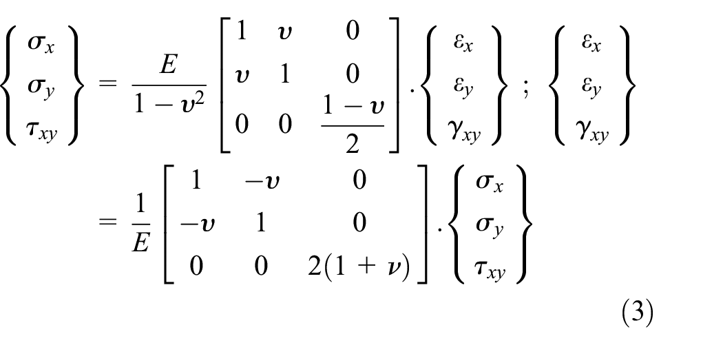
By introducing the Airy function φ (x, y), the stains can be expressed as follows:

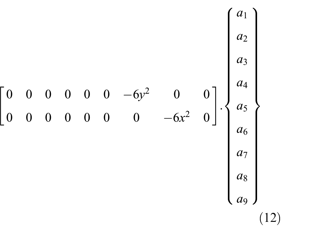
The bi-harmonic solutions of the Airy function φ (x, y) considered for the construction of the interpolation polynomial of the strain field does 33 establish those. Each node of the considered element has three degrees of freedom. Thus the displacement fields, formulated by the use of the strain approach, have nine (9) dependent constants (a1……., a9). As a result, we consider the first nine solutions (see Appendix I):
3 terms leading to rigid body movements,
3 terms leading to linear displacements,
3 terms leading to high order displacements.
Kinematic
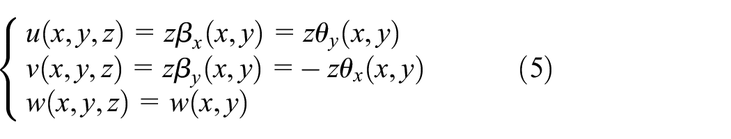
Considering the hypotheses of the Mindlin–Reissner plate theory, the displacements at a point of the solid with reference to a Cartesian axis system are as follows:
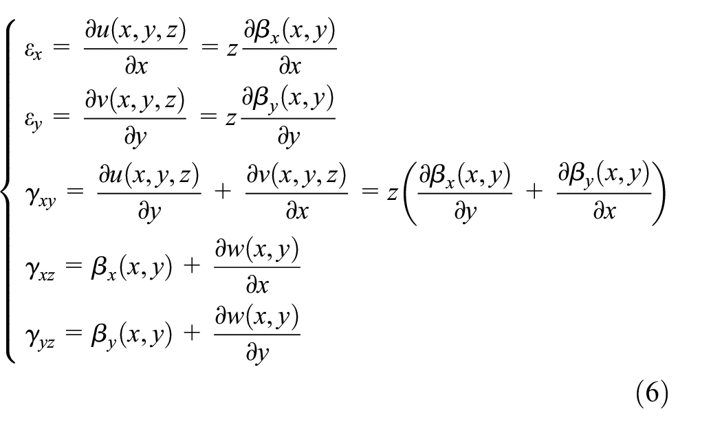
The components of the infinitesimal strain tensor are then:
The moments–curvatures relation are as follows:

Constitutive law
For the plane stress state and for isotropic materials, the generalized behavior law according to the Mindlin–Reissner plate theory is as follow:

With:
E: Young’s modulus, h: the thickness of the plate, ν: Poisson’s ratio, k: the reduction coefficient of the section, generally taken equal to 5/6 for the rectangular sections.
Mx, My, Mxy, Tx, Ty respectively represent the bending moments, the torsion moment and the shear forces for per unit of length.
Strains and displacements fields
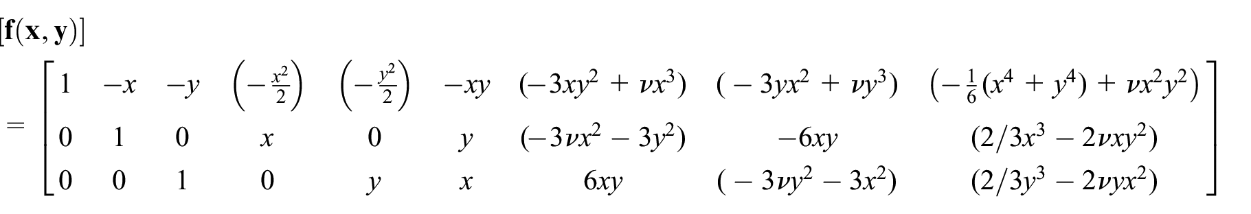
The first nine bi-harmonic solutions of the Airy function φ (x, y) constitute the functions associated with the nine parameters of the interpolation polynomials of the stress fields, the strain fields and finally by integration of the displacement fields. The interpolation polynomials of the bending strain fields (detailed in Appendix I) are obtained by introducing these functions in equation (4). These are as follows:

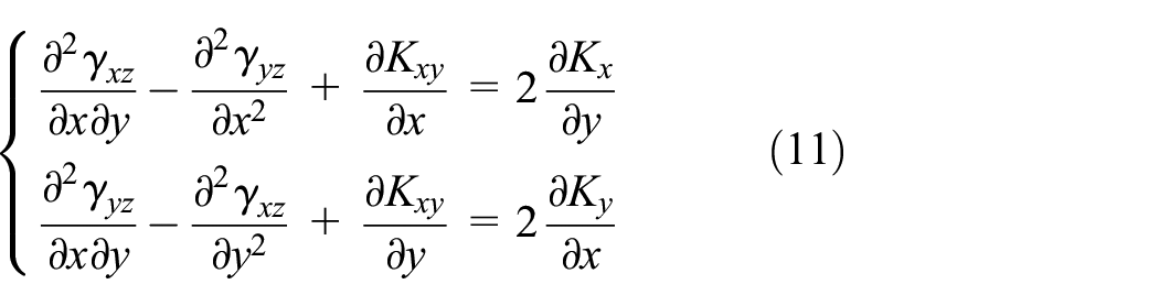
These fields systematically check the equilibrium conditions (equation (1)) and the kinematic compatibility condition:

The interpolation polynomials of the shear strain fields (detailed in Appendix II) are obtained by satisfying the two other kinematic compatibility equations:
These are as follows:

By introducing the strain fields given by equations (9)–(12) into equation (6) and after integration, we obtain the following displacement fields:

With:

Knowing the nodal coordinates (xi, yi) corresponding to the nodes i (i = 1,…,3) and in application of the relation (13), the nodal displacements vector, at the elementary level, is given as follows:

With


From equations (14)–(15), we deduce the value of the parameters ai :

These transformations make it possible to rewrite the kinematics equations as follows:
Displacement fields

Curvature fields related to the moments

With:
Shear strain fields

With:
Elementary stiffness matrix
The elementary stiffness matrix are obtained by application of the virtual displacements principle as follows:
Stiffness related to flexural effects:
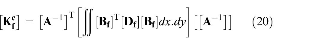
Stiffness related to shear effects:

With:
The evaluation of the expressions
Validation
Mechanical test patch
Several researchers to evaluate finite elements at sate of constants moments34–37 have studied this patch test. A rectangular domain of sides 2a = 40 units and 2b = 20 units, is considered. We impose on the contour of this domain a loading reflecting the state of constants moments. In this example, the domain is discretized by four bending finite elements. In the first case, the moments on the contour are in agreement with the field defined by
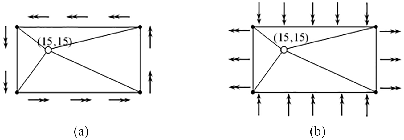
Loading on the contour reflecting the constants moments state: (a) moment defined by

Equivalents node’s forces: (a) first case and (b) second case.
Results of “mechanical” patch test of element Reissner-Mindlin type.

Constant torsion
This test is used to evaluate the ability of finite elements by representing the constant torsion state. It is a square plate (Figure 4) of side L = 8.0, thickness h = 1.0, simply supported (WB = WC = WD = 0) and subjected to a transverse force P = 5 applied to the corner A. The parameters of the material are Young’s modulus E = 10,000 and Poisson’s ratio ν = 0.30. The results obtained by GTMTPFE element are presented in Table 2. The comparison of these results with the exact solution and with those obtained by other elements extracted from the literature, shows a good performance of this element in the representation of constant torsion state.

Torsion of a square plate.
Simulation results of the torsion of a square plate.

Isotropy test
This test is used by Gholami et al.,
38
Kashtalyan,
39
and Plevako
40
in analysis of anisotropic functionally graded plates. It is a square plate simply supported on sides a = 0.9 m and thickness h = 0.3 m. The Young’s modulus varies according to the exponential distribution
Agreement with the general Plevako solution and the DKM method, with regard to the isotropic plate (homogeneous, n = 0),
Rapid convergence of the GTMTPFE element: The result given by the functional gradation plate for the absolute value of the smallest Inhomogeneity parameter (n = 10−6) and in line with that given by the isotropic plate (n = 0).
Performance of GTMTPFE in comparison with current methods and DKM (GTMTPFE discretized with 200 meshes).

Convergence tests
Cantilever beam case
We use the present example to evaluate the behavior of the finite elements in the appearance of the locking phenomenon related to transverse shear. It is a cantilever console beam (Figure 5) subjected to simple bending, clamped at one end and subjected to a point force P = 0.1 N at the other end. The geometric and mechanical data used are length L = 10 m; width b = 1.0 m; Young’s modulus E = 1.2 × 10⁶ N/m2 and Poisson’s ratio ν = 0. This test makes it possible to check the behavior of the GTMTPFE element in simple bending according to the slenderness (ratio L/h). The behavior of the finite element evaluated through the displacement W of the point A in the direction Oz is seen for several reports L/h, h being the thickness of the beam.

Beam-Console subject to a point load.
Based on the Timoshenko beam theory, the exact solution of tip displacement for a plate is available as follows:

With k reduction parameter for rectangular sections equal to 5/6,:
The results obtained by the GTMTPFE element, are given in Figure 6 and Table 4. They show a total absence of the locking phenomenon related to transverse shear, since the displacements obtained converge well toward the theoretical solution when the slenderness is important. The relative error is less than 0.05% for L/h ratio between 4 and 10 and equal to 0.00% for L/h ratio greater than 10, indicating its robustness compared to some existing elements in the literature, particularly for moderately thick plates and for thin plates (L/h ratio greater than 4). It is noting that its modeling has established with twenty (20) elements. We can conclude that:
The GTMTPFE element converges to the analytical solution faster than the DKTM and DSTM elements for thin and moderately thick structures (L/h ratio greater than 4),
The GTMTPFE element converges to the analytical solution faster than the ANST6 element for slender structures.

Displacement WA according to slenderness L/h.
Displacement WA according to slenderness L/h.

N.B: The details of the elements using for comparison in this test are given in Annex III.
Cantilever plate
Rezaiee-Pajand and Yaghoobi 41 have analyzed the behavior of inflectional finite elements regarding their convergence use for test. As it has used to evaluate their response to the blocking problem linked to transverse shear encountered with certain finite elements based on the Mindlin–Reissner theory. It is a cantilever plate (Figure 7) clamped at one end and subjected to distributed shear force q = 4 at the other end. The geometric and mechanical data used are length L = 10 m; width b = 1.0 m; Young’s modulus E = 1.2 × 10⁶ MPa and Poisson’s ratio ν = 0. Based on the Timoshenko beam theory, the exact solution of tip displacement for a plate is available as follows:


Cantilever plate with distributed shear force at the end.
Two steps are considered in this test. First, the GTMTPFE element is subjected to a convergence test with a slender structure (L/h = 100). Then we use the optimal mesh obtained to evaluate its behavior according to a variation in its thickness: from the thickest (L/h = 5) to the thinnest (L/h = 1000). The results obtained by the GTMTPFE element, are given in Figures 8 and 9. They show a total absence of the blocking phenomenon linked to transverse shearing. The displacements obtained converge well to the theoretical solution and are in line with the results of the study realized by Rezaiee-Pajand. 42 Optimal discretization is obtained with 72 meshes. It is noting that, the GTMTPFE element is appropriate for any type of structures (thin and moderately thick). The relative error is less than 0.07% for moderately thick plates (L/h between 5 and 20) and less than 0.04% for thin plates (L/h greater than 20).

Convergence curve for a cantilever plate with load distributed at its end.
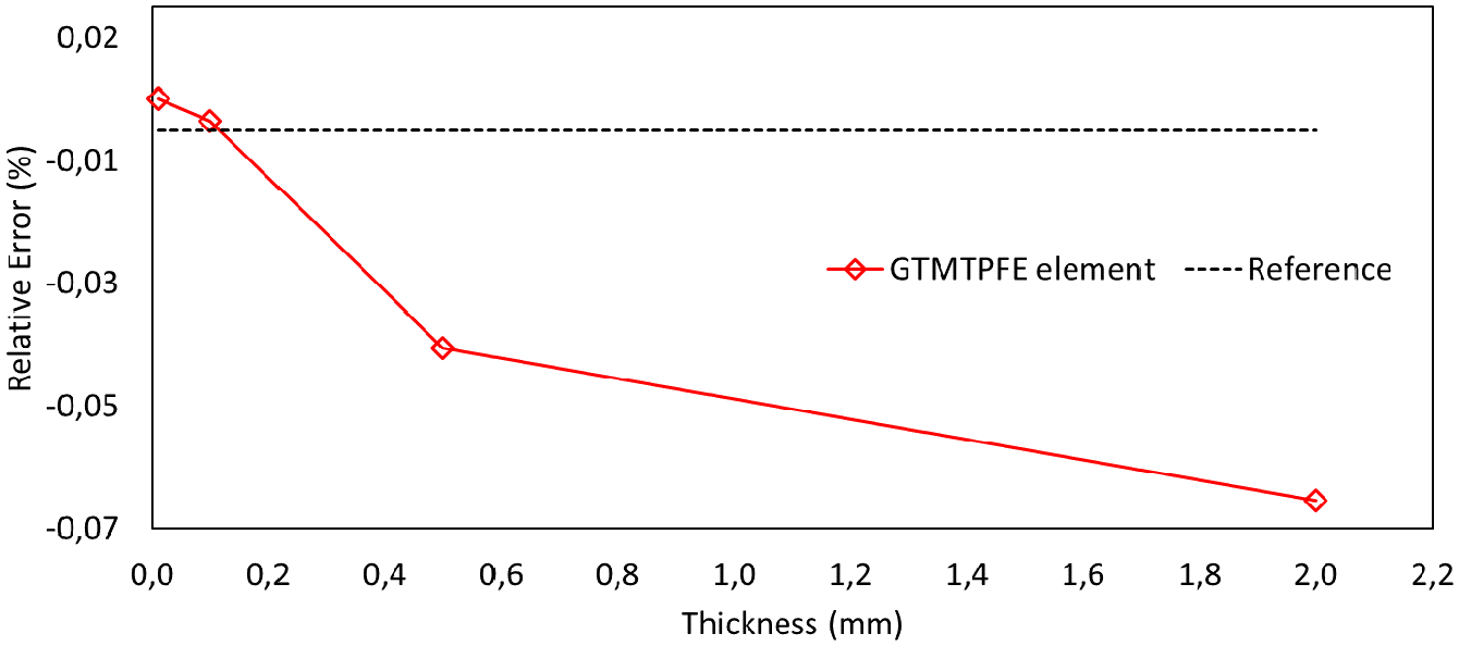
Relative error (%) on the displacement of the free side of the structure according to the variation of the thickness.
Isotropic square plate case
Many authors in literature have studied this example. It is used to check the capacity of finite elements, with respect to their convergence according to the size of the mesh. For this reason, we consider an isotropic square plate with a side a and a thickness h (Figure 10).

Isotropic square plate.
This verification covers a number of different situations depending on the boundary conditions, the type of loading and the slenderness of the plate (a/h ratios). The reference solutions are as follows:
Plate loaded by uniformly distributed load q:

Plate loaded by a force P applied at the center (point C):

With:
According to the boundary conditions and slenderness of the plate, the values of αq and αP are given in Table 5.
Values of

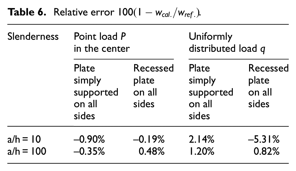
The results obtained for the deflection at the center of the plate (point C) are compared with reference solutions and those of other existing elements in the literature. They are presented in Tables 6 to 10 and illustrated by the Figures 11 to 18. The analysis of these results shows that:
The GTMTPFE element converges well to the reference solution for all simulated situations (boundary conditions, loading type, and slenderness).
There is an excellent performance in approaching the solution. Table 6 show the relative errors observed for a mesh size N = 8.
In view of these observations and comparisons of the results with those of other existing elements in the literature, we notice the robustness of the GTMTPFE element in the treatment of moderately thick and thin structures.
Relative error
Values of α for simply supported plate loaded by uniformly distributed loading q.

Values of α for recessed plate on all sides, loaded by uniformly distributed load q.

Values of α for simply supported plate loaded by point loading P applied in center.

Values of α for recessed plate loaded by a point loading P applied in the center.
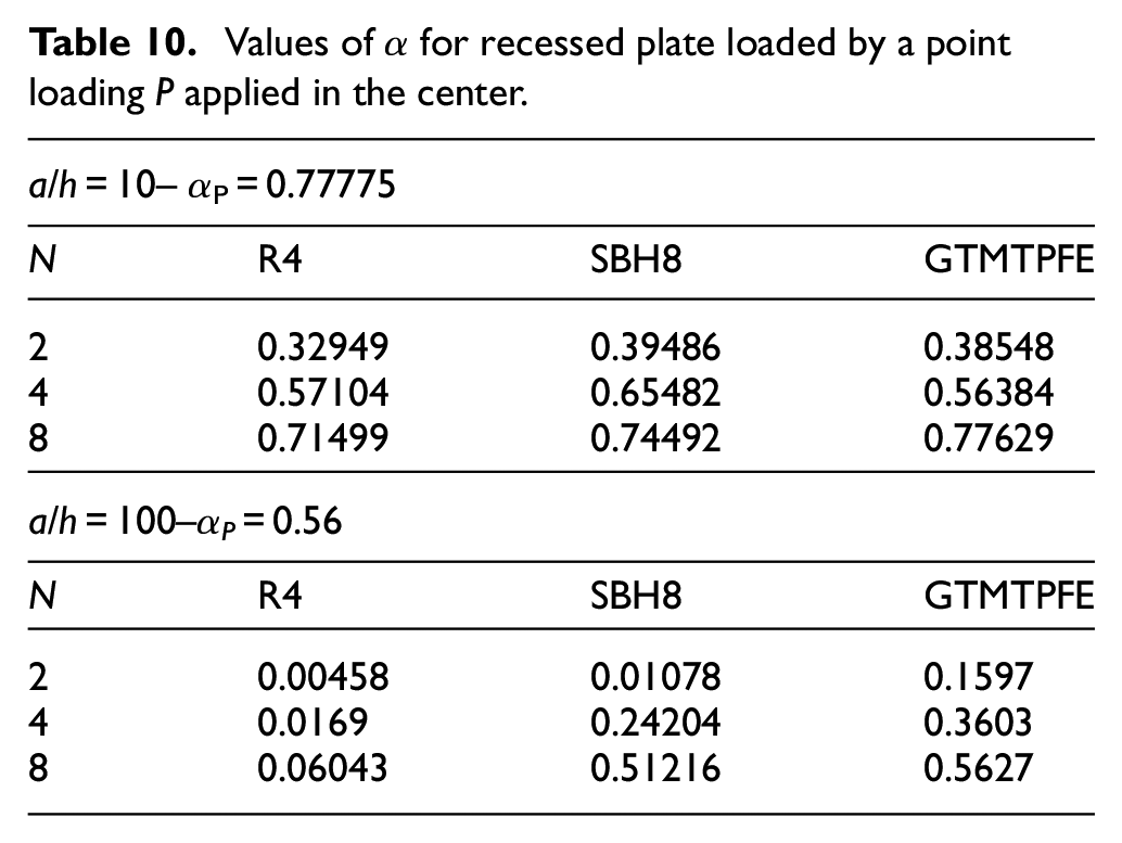
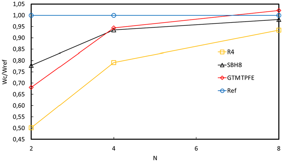
Plate loaded by uniformly distributed loading q – simply supported, normalized displacement for a/h = 10.

Plate loaded by uniformly distributed loading q – simply supported, normalized displacement for a/h = 100.

Plate loaded by uniformly distributed loading q– recessed, normalized displacement for a/h = 10.

Plate loaded by uniformly distributed loading q– recessed, normalized displacement for a/h = 100.

Plate loaded by point loading P applied in center – simply supported, normalized displacement for a/h = 10.

Plate loaded by point loading P applied in center – simply supported, normalized displacement for a/h = 100.

Plate loaded by point loading P applied in center – recessed, normalized displacement for a/h = 10.

Plate loaded by point loading P applied in center – recessed, normalized displacement for a/h = 100.
Circular plate
Several authors in literature, including Batoz and Dhatt, 34 have studied this example. This study is performed according to several nuanced situations based on the boundary conditions of the plate under uniform loading f and slenderness R/h. The plate is discretized info three mesh concentrations: 16, 28, and 112 (Figure 19). The geometric and mechanical data are (R = 5, ν = 0.36, f = 0.1, E = 107).

Circular plate – mesh densities considered.
The reference solutions are:


With:
The results are show in Figures 20 and 21 and the Table 11. Therefore, we have to conclude that the GTMTPFE element exhibits a good behavior with respect to this test and a quick convergence for the different simulated cases. This performance is more significant for the simply supported plate.

Circular plate simply supported, relative error of the displacement in the center.

Circular plate recessed, relative error of the displacement in the center.
Circular plate – displacement in the center.

Skew plates
In this test, the behavior of two diamond skew plates was been investigated. The first case is that of a 60° bias plate subjected to a uniformly distributed load assumed to be simply supported on two sides and free on the other two sides. Its behavior was been studied according to three mesh densities: 4, 8, and 16 elements per side (Figure 22). Three forms of slenderness (L/h = 50, L/h = 100, and L/h = 1000) were considered. The geometric and mechanical data are (L = 100, ν = 0.3, f = 1.0, E = 109).

60° skew plate – mesh densities considered.
The second test, proposed by Morley, 43 with 30° skew plate simply supported on all four sides. It presents a case of very severe behavior since the bending moment has a singularity at the obtuse angle. Due to its symmetry with respect to the diagonals of the plate, a quarter of the plate was been considered by confusing the Ox and Oy axes with the diagonals of the plate (Figure 23). In the same way as in the previous test, three forms of slenderness (L/h = 50, L/h = 100, and L/h = 1000) were studied. The geometric and mechanical data are (L = 100, ν = 0.3, f = 1.0, E = 109).

30° skew plate – mesh densities considered.
The reference solutions obtained by finite differences are as follows:

With:

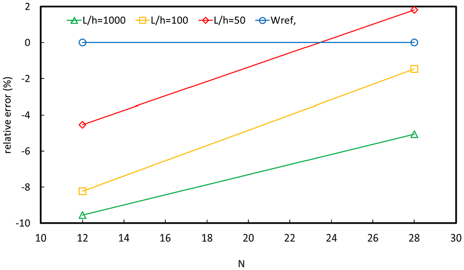
The results were obtained in Tables 12 and 13 and Figures 24 and 25. It can be seen from these results that the GTMTPFE element exhibits a good behavior with respect to these tests and a rapid convergence for the different simulated cases. This performance is more significant for the slender plate. For the 30° bias plate, the configuration of the mesh arranged around the axes of symmetry of the plate (diagonal) permitted significantly faster convergence. Indeed, for a mesh density of 28 elements, the relative error is less than 2% for the L/h ratios equal to 50 and 100 and near to 5% for L/h equal to 1000.
60° skew plate simply supported on two opposite sides – displacement to the center.

30° skew plate simply supported on all sides - displacement to the center.


60° skew plate simply supported on two opposite sides, relative error (%) on center displacement.
30° skew plate simply supported on all sides, relative error (%) on center displacement.
Conclusion
In this study, we present a triangular finite element for moderately thick plate. Its formulation was been based on the strain approach, on solutions of Airy’s functions and on the analytical integration in the construction of the stiffness matrix.
The strengths associated with this approach consist of:
The automatic verification of equilibrium conditions and kinematic compatibility conditions,
The enrichment of the degrees of the interpolation polynomials of displacements, strain, and constraints (refinement p),
The consideration distortions sections related to Poisson effects,
The treatment of blocking phenomena related to transverse shear.
This approach has resulted in a competitive, robust and efficient plate finite element GTMTPFE:
The strain approach for its functional discretization has given the possibility of enhancing the displacement fields, hence a greater precision in the approximation of the solution. This result is very marked in convergence tests, where we observe a rapid tendency toward the exact solution.
The use of the analytic integration in the evaluation of the stiffness matrix gave this element robust behavior with respect to the geometrical distortion of the mesh. This result was significant in tests using distorted and irregular meshes, while for these same tests, the iso-parametric elements (using the numerical integration) are very sensitive (their convergence is conditioned by a regular, undistorted mesh).
The using of the bi-harmonic solutions of the Airy function (by introducing the Poisson’s ratio as variable directly in the fields of interpolation of the kinematics) has allowed taking into account the distortion of the sections following the Poisson effects.
Based on our tests, the first findings indicate:
The stability of the GTMTPFE element with respect to the patch tests carried out, particularly in its behavior with respect to the rigid modes and the modes representing the constant moments.
A behavior marked by the absence of the transverse shear locking.
The suitability of the GTMTPFE element for the treatment of both moderately thick and thin structures.
This is visible through its stability in the face of patch tests (constant twists, state of constants moments, transverse shear locking phenomenon, isotropy test), on the one hand, and in view of its excellent degree of convergence toward the reference solution, on the other hand. It exhibits superior performance behavior to other existing triangular plate finite elements in the literature, particularly for moderately thick plates and for thin plates (L/h ratio greater than 4).
Thus, we present an element that has convincing advantages that call for its use. In perspective, its further development remains necessary. It will be interesting to study its behavior in stresses, in dynamics, in buckling and to reinforce the performances observed here through additional validation tests.
In addition, the GTMTPFE element which treat the bending behavior problems can be combined with the membrane element developed by Himeur et al. 32 to treat problems of complex structures shell.
Footnotes
Appendices
Handling Editor: James Baldwin
Declaration of conflicting interests
The author(s) declared no potential conflicts of interest with respect to the research, authorship, and/or publication of this article.
Funding
The author(s) disclosed receipt of the following financial support for the research, authorship, and/or publication of this article: This work was supported by Directorate General of Scientific Research and Technological Development (DGRSDT) – Ministry of Higher Education and Scientific Research (MESRS) – Algeria.