
Abstract
High-speed railways adopt continuous welded rail to maintain the smoothness and continuity of the rail surface. However, the welded joint became one of the weakest parts. In order to clear the characteristics and mechanical properties of the new reinforced device, a dynamic three-dimensional vehicle-reinforced device-track coupling model is established. The mechanical characteristics of the track structure under high-speed train load were simulated and analyzed. After installing the new reinforced device, the dynamic response and service life of the track structure are obviously improved compared with the unreinforced rail. When the train speed is 300 km/h, the dynamic bending stress at the bottom of rail is reduced by 26.90%, the vertical and lateral acceleration of the rail are reduced by 42.78% and 21.56%, the vertical and lateral displacement of the rail are reduced by 6.36% and 8.67%, and the theoretical service life of the rail is greatly extended.
Introduction
Continuous welded rail (CWR), realizing seamless rails by welding, has become a widely adopted structure over the world owing to its advantages of good smoothness and long service life. However, there are still irregularities at the welded joint, which result in strong dynamic response under the train load. In addition, there are other defects such as inclusions in the welding process, which are prone to crack initiation. Once cracks occur, they will propagate fast, making welded joint become one of the weakest parts of the track and even increasing the possibility of broken-rails, which seriously affects the traffic safety.
Recently, the research of dynamic interaction of train–track system of railway has received extensive attention because it plays an important role in guaranteeing the safety and comfort of the train. Ma et al. 1 discussed the influence of train speed on the wheel–rail contact forces, vertical acceleration of the axle, and other dynamic responses. Miwa and Yoshimura 2 studied the effect of track irregularity on the dynamic response of the train–track system based on the experiments and simulations. Murray and coworkers 3 and Alam et al.4,5 investigated the dynamic contact force and impact forces generated by the train–track interaction due to wheel flats. Wei et al. 6 and Xu et al. 7 characterized the dynamic behavior of the train–track interaction at railway crossings. Wolfs and coworkers, 8 Bezin et al., 9 Zhong et al., 10 and Liu and Zhai 11 studied the influence of creepages, rail roll, wheelset deformation, and polygonal wheel on the wheel–rail contact, respectively. Yang and Kim 12 proposed an effective analytical model to study how installation faults impact the train–track interaction system. For the train–track system of the welded joint in CWR, Steenbergen 13 established a dynamic wheel–rail interaction model for irregularity welded joint, which provided a simplified closed-form solution for describing the dynamic interaction variables. Then, the irregularities of the welded joint and the dynamic responses of train–track interaction in multiple lines were tested. 14 With the establishment of the dynamic train–track coupling model and the mathematical model of short-wave irregularity due to the welding material deterioration, Li et al. 15 found that the irregularity of the welded joint will increase the wheel–rail contact force and increase the dynamic impact loads between the train and the track. Wen et al. 16 and Wang et al. 17 performed a numerical study on the dynamic train–track interactions of different wavelength and depth of irregularities on the welded joints, which showed that the impact loads became larger with the increase of the irregularities, resulting in higher stress and plastic deformation of the welded joint. Thus, it can be seen that a large impact load is easily generated at the welded joint of the rail under the train load, which causes a strong dynamic response and plastic deformation and affects the safety of the train. In order to solve the crazing problem of welded joint, most typical reinforced devices at present are designed to punch holes in the rail and reinforce the joint by splints through bolts.18–20 Zhu and Liu 18 used a finite-element model and a simplified model to study the stress distribution of the splint. David 19 used fish-plates to reinforce the welded joint of heavy-haul railway and optimized the cross-sectional shape of the fish-plate, which was tested by a series of experiments. Xu 20 proposed a structure of a combination of long splint and reinforced plates for heavy-haul railway, and then carried out simulation analysis and indoor static-load experiment. In summary, the previous research mainly focused on general-speed and heavy-haul railways and the conventional reinforced device with bolts. While all conventional methods need to drill holes in the rail, which will make the bolt holes become new fatigue sources. For heavy-haul railways with low train speed, the damage risks caused by the holes can be well prevented and controlled through normal maintenance. On the contrary, the track structure in high-speed railway bears high-frequency periodic reciprocating action. Consequently, any fatigue source will bring unpredictable risks to the high-speed railway. China has 13,000 km high-speed railway with speeds more than 300 km/h. Moreover, the high-speed railway has a short running interval and the maintenance time can only be arranged at night, which determines that the consequences will be disastrous once the rail breaks. Therefore, it is necessary to develop a new reinforced device without drilling, which not only protects the CWR welded joint but also makes no damage to the rail. In fact, China has developed such new reinforced devices to meet these requirements. However, no systematic research has been carried out on this new type of reinforced device. The characteristics and mechanical properties under the high-speed train–load is still unclear, which cannot scientifically guide its engineering practice and restricts its application.
In this paper, we focus on the application of the proposed new reinforced device of CWR welded joint in high-speed railways based on the three-dimensional vehicle–track space-coupled dynamic model. We reasonably optimize the structure and simulate the mechanical characteristics of the CWR welded joint with the new reinforced device and comparing it with the rail joint without reinforcement. Meanwhile, we also make comparative analysis of the fatigue life of CWR with or without the reinforced device. Our work provides theoretical support for high-speed railways to realize high-security, high-smoothness, and high-reliability.
Working principle of new reinforced device
The new reinforced device consists of splints, adhesive and clamps as shown in Figure 1. The cross-section of the splint is designed into a reasonable shape to improve the bending resistance and optimize the overall stiffness of the track. The splint is glued to the jaw, the slope, and the waist of the rail in full section to maximize the glued area. The adoption of adhesive bonding helps avoid stress concentration caused by drilling. At the same time, it has better fatigue resistance when it is subjected to vibration or repeated load and has excellent sealing performance against water, air or other environmental media. The clamps outside apply lateral pushing force to the splint to prevent the splint from falling down due to long-term employment.

Cross-section of the new reinforced device.
It is found that wheel-load plays a decisive role in crack propagation within 1/4 span near oblique cracks. 21 The spacing of the fasteners used in this paper is 0.65 m, so the theoretical minimum length of the splint is calculated to be 0.325 m (1/4 m × 0.65 m+1/4 m× 0.65 m). However, the overlong splint may lead to excessive mid-span deflection and waste. Considering other factors such as installation tolerance, the splint length range is initially determined to be 0.4 to 1.4 m. The specific analysis will be described in detail in the following Sections.
The remaining design of the new reinforced device needs to comprehensively take the factors such as joint resistance, bending stiffness, and integral stiffness of the track into account.
Joint resistance
The rail joint resistance can be described as the anti-shear force generated on the bonding surfaces of splints under the condition that the adhesive surfaces do not produce detachment force, whose value mainly depends on the bonding strength and the bonding area. When the bonding strength is constant, the shear force (Q) of the adhesive and the bonding area (S) are in positive proportion as shown in equation (1).

Here
Bending stiffness
The bending stiffness determines the ability of rail to resist dynamic bending stress. The dynamic bending stress (


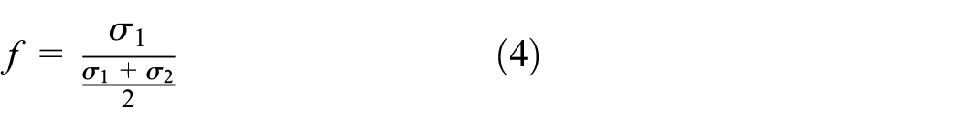
where
Integral stiffness of track
Track stiffness is an important parameter affecting vibration and deformation of the track, safety and stability of train as well as track maintenance.22–24 Considering various factors, such as maintenance and comfort, the integral stiffness in high-speed railway is generally controlled at 50 to 100 kN/mm in practical. 25 The optimal stiffness of track is 75 kN/mm when the train speed exceeds 300 km/h. 26 As a result, the cross-section of the splint is designed to be narrow up and down, thick in the middle.
Vehicle–track dynamic model
Establishment of dynamic model
Based on the vehicle–track coupled dynamics principle,27,28 a three-dimensional vehicle–ballastless track space-coupled dynamic analysis model was established by a finite-element software (ABAQUS). The dynamic analysis model consists of a vehicle model, a ballastless-track model, and a wheel–rail coupled contact model as shown in Figure 2.
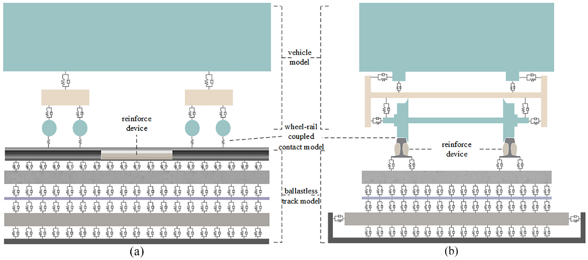
Three-dimensional vehicle–track space-coupled dynamic analysis model.
Vehicle model
The geometric model of the train is built based on CRH3-train. The vehicle model consists of train-body, bogie, and wheelset as shown in Figure 2. In the process of modeling, the following assumptions are made 28 :
The train-body, bogie, and wheelset are regarded as rigid bodies, whose elastic deformation is not considered in the calculation and analysis process.
The mass of train-body, bogie, and wheelset is designed symmetrically, without considering the influence of eccentric action.
In this paper, the model of CRH3-train comprehensively considers the functions of primary suspension and secondary suspension. The primary and secondary suspensions are simulated by Cartesian beam and the bogie is connected to the train-body by MPC beam, which has a total of 31 degrees of freedom.
Track model
As shown in Figure 3, CRTSII ballastless-track model on subgrade consists of rail, reinforced device, fastener, slab, CA mortar layer, plate, etc. The rail is simulated by solid elements with densification of grid. High-speed railways adopt CWR, which is achieved by flash welding. In the finite element model, the welded joints are simulated by solid elements. In order to study the mechanical characteristics of the welded joint, fine meshing is performed. The welded rail section and base metal are considered to have different material properties by setting different elastic modulus and Poisson’s ratio. The base metal of the rail and the welded joint are all simulated by C3D8I non-coordinated mode element, 29 and other areas are simulated by C3D8R reduced integration element. The splints and rails are connected with adhesive on site, which is simulated by the tie condition in the finite element model. The fastener is simulated by a spring element, which has two parameters of stiffness and damping. The splints, clamps, slab, CA mortar layer and plate are all simulated by solid elements through C3D8I uncoordinated mode units.

The schematic diagram model of track structure.
Wheel–rail coupled contact model
The vehicle model and the track model are spatially coupled through wheel–rail contact model. The wheel–rail normal force is calculated according to Hertz nonlinear-contact theory. The wheel–rail creep force is solved by Kalker linear theory and is corrected nonlinearly by Shen’s theory.
28
The vibration equation of the vehicle–track coupled dynamic model is as equation (5), where


Wheel–rail coupled contact model.
Parameters of dynamic analysis
Vehicle parameters
According to the parameters of the main types of trains in China high-speed railways, the axle load of CRH3-train is 15 time and the weight of bogie and wheelset are 3200 and 2400 kg, respectively. The damping and stiffness of the primary and secondary suspension are shown in Table 1.
Parameters of suspension system.

Track parameters
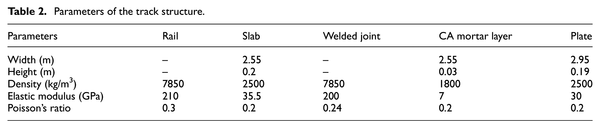
Geometrical and mechanical parameters of the track structure are determined according to the relevant design regulations for high-speed railways in China. The mechanical parameters’ values involved in this paper include density, elastic modulus, and Poisson’s ratio are shown in Table 2.
Parameters of the track structure.
New reinforced device parameters
The materials of the splint and clamp in the new reinforced device are selected based on the relevant regulations of China. 30 The specific parameters are shown in Table 3.
Parameters of the new reinforced device.

Field experiments and model verification
The new reinforced device is a new component for track structure, which has not yet been applied to the high-speed railway and no experimental research of the new reinforced device has been carried out. Thus, we compared the test data and the numerical results without the reinforced device. Then, the verified model is equipped with the new reinforced device. In addition, considering the actual situation on site, tie contact is adopted to simulate the bonding of the new reinforced device on the rail in the subsequent simulation.
Layout of measuring points
Dynamic bending stress is the main cause of rail fracture. Under the action of the dynamic load of train, the rail undergoes downward bending deformation, which means that the lower region of the rail will be stretched longer and the upper region will be compressed shorter. At this time, the energy dissipation is different from the pure tangential force. 31 With the repeated dynamic bending stress, the rail will bear accumulatively enlarged plastic deformation, forming micro cracks on the surface or sub-surface of the welded joint. The cracks are also subjected to tensile and compressive actions,32,33 which will continue to extend and cause rail fracture eventually. Besides, the vertical displacement is also one of the important indexes to evaluate the track. When the vertical displacement is too large, the deformation of the rail is huge and the welded joint, as the most vulnerable part of the rail, is prone to fracture. As is mentioned above, they are the evaluation indexes which can best reflect the changes of dynamic responses of the track structure. In addition, the dynamic bending stress and vertical displacement are convenient to measure and the test data have obvious features. Consequently, the experiments of dynamic bending stress and vertical displacement of the rail are carried out to realize the verification of the model.
The dynamic experiments of track are located at the straight section of high-speed railway, whose track structure is CRTSII slab ballastless track with 60 kg/m rail laying, fasteners spacing of 0.65 m and subgrade as the foundation. The speed of the test train is 300 km/h. As shown in Figure 5, the measuring points of the dynamic bending stress and the vertical displacement are respectively located at the mid-span positions of the upper and lower surfaces of the rail’s bottom. The pictures of field experiments are shown in Figure 6.
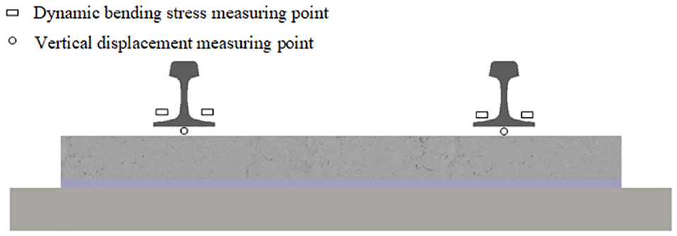
Schematic diagram of measuring points for dynamic bending stress and vertical displacement of rail.

Pictures of field experiments for (a) dynamic bending stress and (b) vertical displacement.
Model verification
In this section, we mainly verify the correctness of the model by identifying the consistency of dynamic bending stress and vertical displacement in field experiments and simulations.
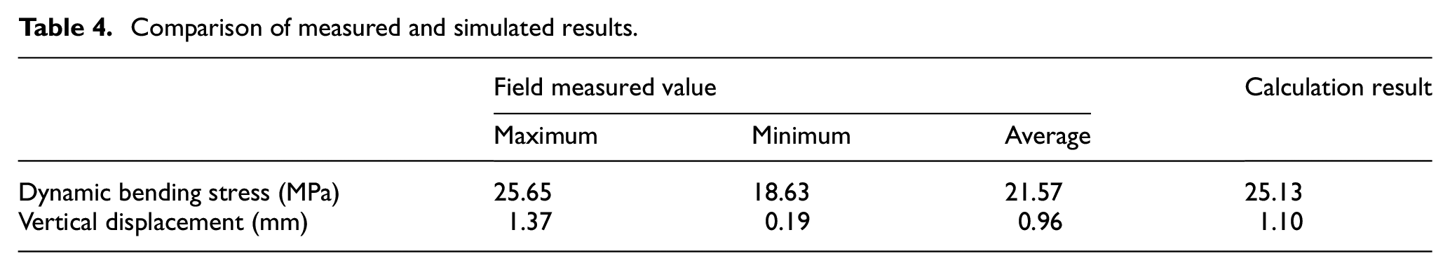
The results of dynamic bending stress and vertical displacement measured by on-site tests in high-speed railway and the results calculated by the vehicle–track coupled model are shown in Figure 7 and Table 4. As can be seen from Figure 7 and Table 4, the time-history curve of the test results and simulation analysis results are basically the same. The average values of dynamic bending stress and vertical displacement of the rail obtained from the experiments are 21.57 MPa and 0.96 mm respectively. The simulation results are slightly larger than those, which are 25.13 MPa and 1.10 mm respectively, owing to the fact that the irregularity applied in the model is slightly different from the actual situation. However, the calculation results are still between the measured maximum value and minimum value. Therefore, the simulation model and calculation method can be considered reliable.
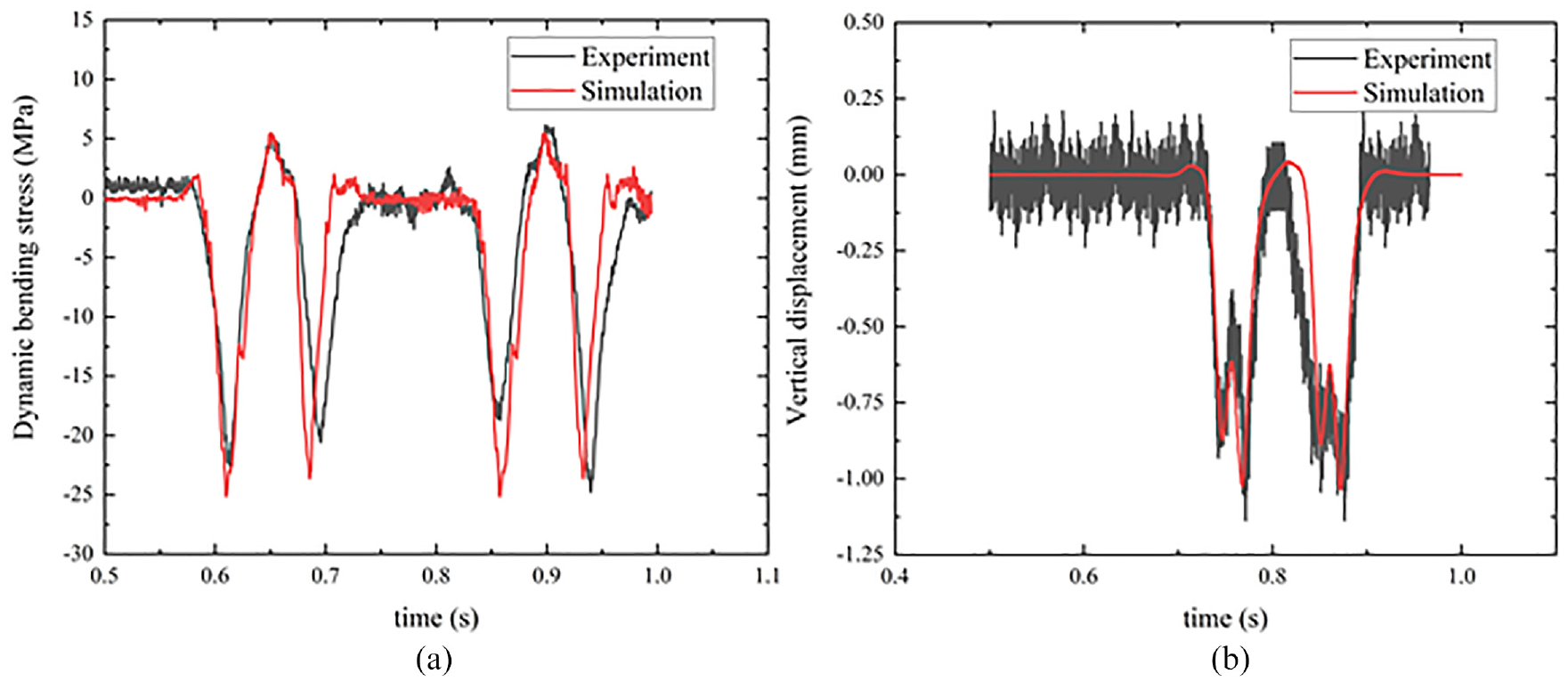
Comparison of time-history curves of experiment results and simulation results: (a) dynamic bending stress and (b) vertical displacement.
Comparison of measured and simulated results.
Based on the validation, the new reinforced device is only added at the welded joint by tie contact, while other model parameters remain unchanged compared with the model without reinforcement, so as to ensure the correctness of the model calculation.
Analysis on dynamic characteristics of rail with reinforced device
In this section, we change the length of splint (L = 0.4–1.4 m), clamp tightening force (F = 0–50 MPa) and speed (V = 200–350 km/h) to analyze the corresponding influence on the dynamic characteristics of the rail with the new reinforced device in the three-dimensional vehicle–track space-coupled dynamic model, while other parameters are kept constant.
Influence of splint length on dynamic characteristics
The length of the splint (L) determines the adhesive force between the rail and the splint. Considering the installation tolerance, cost, and other factors, the dynamic response of rail with the new reinforce device under different splint lengths (L = 0.4, 0.6, 0.8, 1.0, 1.2, and 1.4 m) is calculated and analyzed. When the train speed is 300 km/h, the dynamic bending stress of the rail (Figure 8), the time-history curves of dynamic characteristics (unloading rate, derailment coefficient, vertical and lateral acceleration of rail, and vertical and lateral displacement of rail; Figure 9) and the maximum values of dynamic characteristics (Table 5) with different splint lengths are calculated.

Simulated results of dynamic bending stress response of rails with splint lengths of (a) L = 0 m, (b) L = 0.4 m, (c) L = 0.6 m, (d) L = 0.8 m, (e) L = 1.0 m, (f) L = 1.2 m, and (g) L = 1.4 m. (h) Fitted max values of dynamic bending stress versus splint length (L).
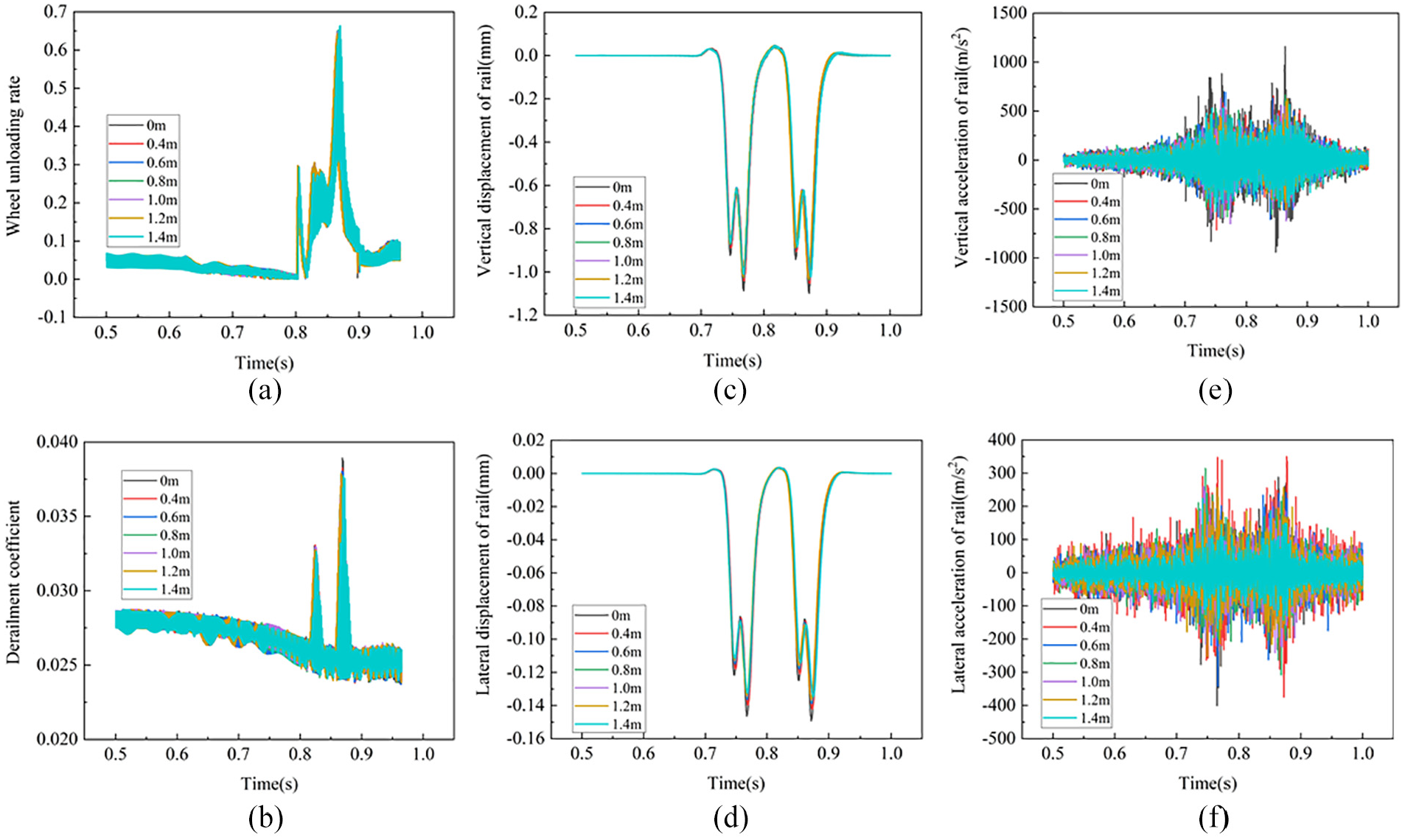
Time-history curves of dynamic-response with different length of splints: (a) wheel unloading rate, (b) derailment coefficient, (c) vertical displacement, (d) lateral displacement, (e) vertical acceleration, and (f) lateral acceleration of rail.
Calculated results of dynamic characteristics of rails with different splint length.

As shown in Figure 8(a)–(g), the nephograms show that the maximum dynamic bending stress at the bottom of the rail obviously decreases with the increase of the splint length within the range of 0 to 0.8 m. When the length exceeds 0.8 m, the amplitude of the drop becomes very small. The maximum value of the dynamic bending stress is extracted and fitted as shown in Figure 8(h). It can be seen that the decline rate of dynamic bending stress gradually slows down and converges to 18.37 MPa finally. At this time, the dynamic bending stress is reduced by 6.76 MPa (26.90%), compared with that without the reinforced device. Figure 9(a)–(f) shows the time-history curves of each parameter of the rail with different splint lengths. Compared with those without reinforcement, the waveforms of time-history curves of dynamic response are similar while the maximum values are reduced. According to the curves, the maximum values of each parameter are extracted as shown in Table 5. Obviously, the vertical and lateral displacement of the rail first decreased with the increase of the splint length and then stabilized after the length of 0.8 m, reaching 1.03 and 0.137 mm with a decrease of 6.36% and 8.67% respectively, which are similar to the tendency of dynamic bending stress. Other dynamic characteristic parameters also decrease, among which the vertical acceleration of rail has maximum change with a drop of 38.44%. The lateral acceleration of the rail decreases linearly with the length of the splint. For every 0.2 m increase of the length of the splint, the transverse acceleration of the rail decreases by about 3.12 g (g = 10 m/s2). The decreasing range of unloading rate and derailment coefficient are 0.47% to 2.02% and 1.80% to 3.08%, respectively. To sum up, with splints equal to or longer than 0.8 m, the reinforced device can effectively reduce the dynamic effect of train load on the track structure, better control the deformation of the structure and then reduce the probability of welded joint damage. Therefore, the best length of the splint is selected to be 0.8 m considering the cost and influence on the dynamic characteristics of rail.
Influence of clamp tightening force on rail dynamic characteristics
By applying a certain horizontal tightening force with the clamp, the bonding state between the splint and the rail can be enhanced so as to prevent the possibility that the splint is separated under adverse conditions. According to the analysis of the stress state of other bulging splints and take the material properties of our splints into consideration, the maximum value of the applied tightening force (F) is determined to be 50 MPa. Keeping the splint length 0.8 m and the speed of train 300 km/h, the dynamic response of the track structure under different tightening force (F = 0, 10, 20, 30, 40, and 50 MPa) is calculated. The calculated results of dynamic bending stress and other dynamic characteristic parameters of the rail are shown in Table 6 and Figure 10.
Calculated results of dynamic characteristics of rails under different clamping tightening force (F).


Typical nephograms of dynamic bending stress response of rail under tightening force of (a) F = 0 MPa, (b) F = 10 MPa, (c) F = 20 MPa, (d) F = 30 MPa, (e) F = 40 MPa, and (f) F = 50 MPa. (g) The max values of the dynamic bending stress response versus tightening force.
As can be seen from Figure 10, the dynamic bending stress at the bottom of the rail slightly increases with the increase of tightening force. When the tightening force increases from 0 MPa to 50 MPa, the dynamic bending stress increases by 0.96 MPa (5.23%). It can be seen that the magnitude of lateral additional tightening force has little effect on the stress of the rail. Through Table 6, the vertical and lateral acceleration of the rail are obviously reduced by increasing the tightening force of the clamp, with the maximum reductions of 15.32% and 21.84% respectively, while other dynamic characteristics indexes (unloading rate, derailment coefficient, and vertical and lateral displacement of the rail) are basically unchanged. They reflect that applying a certain level of tightening force to the splint can strengthen the adhesion effect between the splint and the rail, yet has little influence on the dynamic characteristics of the rail. As a result, clamps generally play an auxiliary role to prevent splints from falling off due to long-term employment. When installing the device on-site, it is suggested to cancel the clamp and use more concise devices to prevent the splint from slipping, so as to improve the efficiency and reduce the cost.
Influence of train speed on rail dynamic characteristics
The dynamic response of the track structure is related to the running speed of the train. According to the actual speed of China high-speed railway, the dynamic response of the rail with the new reinforced device at speed (V) of 200, 250, 300, and 350 km/h is calculated under the condition that the splint length is 0.8 m and no clamp tightening force is applied, whose results are shown in Figures 11 and 12 and Table 7 respectively.

Calculated results of rail dynamic response: (a) dynamic bending stress, (b) wheel unloading rate, (c) derailment coefficient, (d) vertical displacement, (e) lateral displacement, (f) vertical acceleration, and (g) lateral acceleration of rail at different speed of train.

Typical nephograms of dynamic bending stress response of rail under speeds of (a) V = 200 km/h, (b) V = 250 km/h, (c) V = 300 km/h, (d) V = 350 km/h without new reinforced device, (e) V = 200 km/h, (f) V = 250 km/h, (g) V = 300 km/h, and (h) V = 350 km/h with the new reinforced device.
Calculation results of rail dynamic characteristics with different train speed.

As can be seen from Figures 11 and 12 and Table 7, the installation of the new reinforced device can mitigate the dynamic response of the track structure at different speed. Compared with that without reinforced device, the drop of the dynamic bending stress, vertical displacement and vertical acceleration of the rail gradually go up with the increase of the train speed after installing the new reinforced device. When the speed reaches 300 km/h, the decrease is 26.9%, 6.36%, and 42.78% respectively. It indicates that the new reinforced devices can effectively reduce the dynamic response of the track structure at the welded joint in high-speed railway.
Fatigue life analysis
In engineering structures and mechanical equipment, fatigue damage generally exists in the components that bear cyclic loads. As an important part of the track, the rail directly bears the load of wheel–rail contact and transfers the upper load to lower structures such as plates. The state and the service life of the rail directly affect the railway transportation. 34 As is mentioned above, CWR is formed by welding. Various defects in the welded joint are easy to cause the discontinuity of welding materials and mechanical properties of the rail, which make the bending fatigue of the welded parts become the main factor determining the fatigue life of the rail. 34 Studying the fatigue life of the welded joints can provide reasonable parameters for the use and research of the rail, thus promoting the rational use of rail and maximizing the utilization of resources. It is of great significance for guiding maintenance, prolonging the service life of the rail and saving steel resources. In this section, we analyze the fatigue life of the rail based on the Palmgren–Miner fatigue cumulative damage theory 35 and the Fe-safe fatigue analysis software. 36
The Miner’s fatigue damage theory is based on the following assumptions:
Each load cycle will cause certain damage to the life of the components, and the damage caused by each cycle is 1/N (N is the fatigue life);
Fatigue damage will occur when the energy absorbed by the components reaches the threshold. The energy is proportional to the ratio of the cycles of stress and cycles of damage under the certain stress;
The total amount of damage when the sample reaches destruction is a constant;
The damage is independent of the order of load.
Once the sum of all damage caused by multi-cycle stress is 1, the sample will be destroyed.
During the loading process, the components are subjected to different levels of stress such as

The total damage amount for each cycle is:
The total period during which the components are loaded is:

The fatigue life is:

During the fatigue life analysis, the results of finite-element calculation obtained from ABAQUS at different train speed are imported into Fe-safe for fatigue calculation, and then the fatigue analysis results are imported into ABAQUS for visual analysis to obtain the fatigue life nephograms of the rail. The fatigue calculation process is shown in Figure 13.

Process of fatigue life calculation in FE-SAFE.
According to the stress characteristics of the rail, its fatigue life mainly depends on the train load. Based on the actual operation of the high-speed railway, fatigue analysis is carried out on the rail with or without reinforced device at the speed of 200, 250, 300, and 350 km/h respectively, whose calculation results are shown in Figures 14 and 15. Statistics of the fatigue life are shown in Table 8.
Typical nephograms of fatigue life at welded joint without reinforced device at different speed (a) V = 200 km/h, (b) V = 250 km/h, (c) V = 300 km/h, and (d) V = 350 km/h.

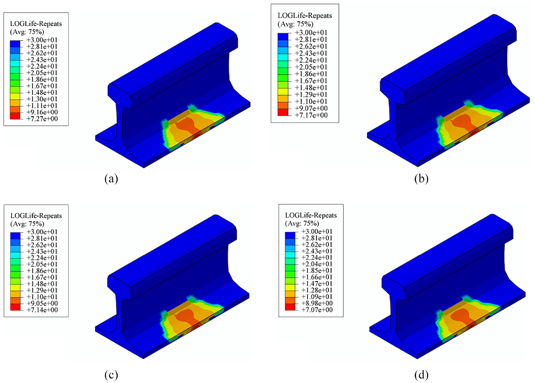
Typical nephograms of fatigue life at welded joint with the new reinforced device at different speed (a) V = 200 km/h, (b) V = 250 km/h, (c) V = 300 km/h, and (d) V = 350 km/h.
Fatigue life of the rail at different train speed.

As can be seen from Figure 14, the rail first produces fatigue damage in the middle of the edge of the rail bottom under the action of train load, which then continuously develops towards the surroundings. With the increase of train speed, the fatigue life of the rail decreases. As the train speed increases from 200 to 350 km/h, the fatigue life of the rail decreases by 36.90%. After installing the new reinforced device, the fatigue life of the rail is significantly improved, which shows the increase of 47.91% to 81.97% at different speed as shown in Table 8. Moreover, the faster the train runs, the more obvious protection of the rail and more significant improvement of the fatigue are achieved. In addition, the fatigue-risk range (dark area) is also reduced after the reinforced device is installed as shown in Figure 15.
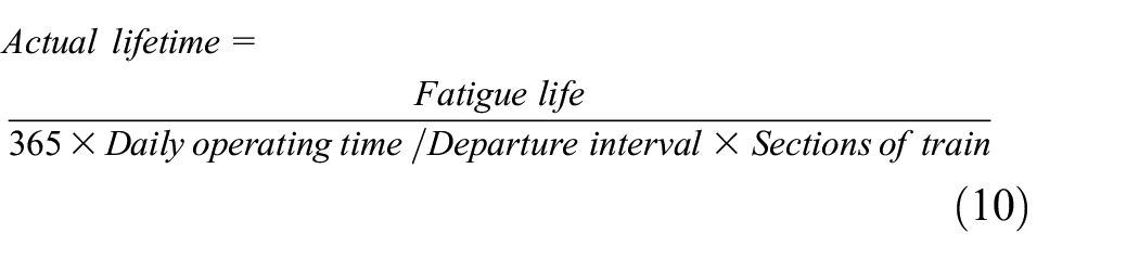
In order to convert the fatigue life of the rail into actual lifetime, the equation (10) is used for calculation
We assume that the departure interval of high-speed railway is 5 min/time, the daily operation time is 18 h and each train consists of eight sections. The calculated actual lifetime of the rail at different speed is shown in Table 9.
Actual lifetime of the rail at different train speed.

It can be seen that the actual lifetime of the rail is reduced from 29.25to 18.63 years as the speed increased from 200 to 350 km/h when the welded joint of the rail is not protected. After the reinforced device is installed, the actual lifetime can be increased to 43.77, 36.32, 35.49, and 33.90 years respectively. It indicates that the installation of the reinforced device can greatly prolong the replacement period of the rail, reduce the times of maintenance, especially reduce the risk of the breakage, which is of great significance to ensure the safety of high-speed railways.
Conclusion
To solve the problem of the fracture of welded joint in high-speed CWR, we take the lead in systematically analyzing the reasonable structure of the new reinforced device and the mechanical characteristics of the track structure with or without reinforced device as well as the influence on the fatigue life of the rail based on establishing the vehicle-new reinforced device space-coupled analysis model. The conclusions obtained are as follows:
The cross-section of the new reinforced device can be determined according to the reasonable stiffness of the track structure and the overall stress of the rail. The splint is glued to the rail in full section and the clamp plays an auxiliary role. The optimal length of the splint is 0.8 m.
The mechanical properties of the track structure can be obviously improved after installing the new reinforced device. Under the condition that the train speed is 300 km/h, the dynamic bending stress of the rail can be reduced by 26.90%, the vertical and lateral acceleration of the rail can be reduced by 42.78% and 21.56%, respectively, and the vertical and lateral displacement of the rail can be reduced by 6.36% and 8.67%, respectively, compared with that without the reinforced device. The results show that the installation of reinforced device is helpful to enhance the cooperative stress of track structure and slow down the vibration impact of train load.
The use of reinforced device can significantly improve the fatigue life of the rail. When the train speed is 300 km/h, the fatigue life of the rail can be increased by 62.18% and, theoretically, the actual lifetime of the rail can be extended by 13.61 years, thus greatly reducing the times of maintenance and the operation cost of the high-speed railway.
Footnotes
Handling Editor: James Baldwin
Declaration of conflicting interests
The author(s) declared no potential conflicts of interest with respect to the research, authorship, and/or publication of this article.
Funding
The author(s) disclosed receipt of the following financial support for the research, authorship, and/or publication of this article: This work was supported by the National Natural Science Foundation of China (Grant no. 51978045) and Technology Research and Development Plan of China National Railway Group (P2018X011).