
Abstract
A fuzzy control strategy is developed in this study to manage the parallel hybrid power system of internal combustion engine (ICE) and electric motor (EM) for hybrid vehicles. The rules established for the fuzzy logic are based on the conditions of vehicle pedal position, vehicle velocity, and the state of charge to control the throttle position of the ICE and the switch position of EM in low-, mid-, and high-power cruising. The optimization of the control strategy can make vehicles achieving ECE 40 driving pattern. In addition, the ICE can work in an optimal operation range, thus reducing carbon emission. The EM may provide power according to the demand, such that the torque output of the output shaft of the power split device is twice of the input of the two power sources separately.
Introduction
Hybrid vehicles are a combination of an internal combustion engine (ICE) and electric motor (EM).1,2 A suitable hybrid configuration of the ICE and EM can improve the power output and overcome the challenges of insufficient battery life and inconvenient charging of electric vehicles.3,4 According to the different power transmission and distribution methods, hybrid vehicles can be divided into the parallel and series type. 5 Series hybrid vehicles are more suited for driving at low speeds in the city, because a series power source is easy to maintain in the optimal operating range at low speeds. 6 Moreover, the ICE and EM of a parallel system are connected to the transmission shaft through a power integration device or a transmission device. The vehicle can be driven by the ICE and EM simultaneously or independently. Consequently, once the ICE was operated in the optimal operating range through a proper dynamic programming 7 and a power management strategy, 8 the fuel economy of parallel hybrid vehicles can be higher than that of series hybrid vehicles.
Furthermore, fuzzy logic controllers were proposed to improve the energy efficiency of hybrid vehicles in parallel configurations 9 even with functions of machine learning 10 and adaptive-equivalent strategy. 11 The basic principle of fuzzy rules is to classify complicated input conditions into operation intervals to optimize output efficiency. Therefore, fuzzy logic was demonstrated to have the potential to improve fuel economy which maximizes engine efficiency. For example, Lee et al. 12 used driver commands, the battery state of charge (SOC), and motor/generator speed as input conditions to establish a fuzzy logic control rule database and efficiently distribute power for smoother energy transmission. Powell et al. 13 derived the dynamic equations between the components of a parallel hybrid vehicle to model each component. Giorgio et al. 14 established a hybrid power simulation module to achieved high fuel efficiency under the predefined driving conditions. Karen et al. 15 designed a power transmission simulation module to analyze the fuel efficiencies of parallel hybrid vehicles. Powell et al. 16 simulate the energy transfer of a continuously variable transmission (CVT) in parallel hybrid power systems, indicating that the CVT could transfer most of the ICE torque to the wheels, and the gear ratio can be used to adjust the speed of the ICE for improved energy distribution. Bowles et al. 17 established a forward simulation of a hybrid power system to maintain the ICE and CVT. Bernd et al. 18 used fuzzy logic and control principles to optimize the energy distribution. Salman et al.19,9 used a fuzzy logic database as the energy management to optimize the fuel economy of parallel hybrid vehicles. Chau and Wong 20 proposed parallel hybrid power and power flow control methods, suggesting that the ICE be controlled within the lowest fuel consumption range and the maximum torque range. Xiaoling and Hodgson 21 developed an electric-assisted hybrid vehicle in a parallel configuration that allows for the real-time input of a wide range of vehicle parameters to evaluate the power control strategy. Bailey et al. 22 constructed a system controller based on the driver’s demand and energy management scheme, thereby reducing the effect of bumpy roads on the driver. Wagner 23 used a non-linear control strategy to regulate the air-to-fuel ratio and engine speed for hybrid vehicles. Wong and Langari24,25 used a fuzzy torque distributor and the SOC to distribute the ICE torque; thus, they improved fuel efficiency by developing the intelligent energy management control strategy. Lin et al. 26 applied the parallel hybrid power system to trucks and verified that the fuel economy and nitrogen emissions of the hybrid trucks were better than those of fossil fuel vehicles using three predefined power distribution strategies.
However, the control rules in the previous literatures for fuzzy logic were not sufficient to meet the demands of diverse driving conditions. In addition, there was a lack of using fuzzy logic combining power split mechanism to make an optimal power distribution between ICE and EM. Therefore, this study conducts using a forward simulation of hybrid power systems to address the effect of inputs in pedal position, vehicle velocity input, and SOC on the appropriate adjustment of the throttle and switch positions of ICEs and EMs through a fuzzy power distribution device. To further optimize the energy utilization rate of the energy control system of parallel hybrid power systems, in this study, we applied dynamic equations and fuzzy theory to develop energy management strategies for different driving scenarios. Based on the concept of power distribution, we established an ideal adjustment rule database that determines the power output of the ICE and EM according to different driving conditions. The optimal distribution of the ICE and the EM provide power to the vehicle to maintain the ICE in the optimal operating range, and at the same time, the EM provides different power amounts according to the demands, to meet the driving needs of the vehicle.
Material and methodology
Energy control strategy for the hybrid power system
The hybrid power system includes a power split device (PSD), ICE, EM/generator, battery, electric continuously variable transmission (ECVT) system, electronic control unit, accelerator pedal, and tachometer. The flow of the energy control strategy is shown in Figure 1. Flow Overlap 1 in Figure 2(a) is for the system to determine the means of shutting down the ICE and the motor to prevent the ICE from turning on and off constantly, causing power loss and pollution. Flow Overlap 2 in Figure 2(b) is for the system to determine the means of shutting down the motor and starting the ICE—this is to smoothen the power transition. The controls for all power output modes are described below.

Flow chart of the energy control strategy for the hybrid power system.

Flow charts of: (a) overlap 1, (b) overlap 2.
Power output mode of the EM
When a vehicle starts from a standstill, the battery can be used to start the EM to move the vehicle when the SOC is more than 40%. The speed of the EM is modulated by the current that is controlled by the electronic control unit; the EM drives the first helical gear, which in turn drives the third helical gear, and the third helical gear outputs power to the ECVT around the rotary shaft. At this time, the ICE is not running because of the one-way clutch.
Power output mode of the ICE
There are two scenarios. The first scenario is when the power of the vehicle reaches a specific range, and the power output by the EM is less than the power required by the final output shaft. At this stage, the electronic control unit starts the ICE and then turns off the EM. This allows the ICE to swiftly operate and maintain the optimal operating condition in this range. Next, the output is switched to the ICE driven mode; the ICE drives the second helical gear, which in turn drives the third helical gear, and the third helical gear outputs power to the ECVT around the rotary shaft. At this time, the EM is reverse driven by the second helical gear; if the SOC is less than 80%, it drives the generator to generate electricity to charge the battery. The second scenario is when the SOC is too low to start the EM to drive the vehicle; then, the ICE is started as the power output to drive the vehicle, and at the same time, the generator is driven to store excess energy into the battery.
Dual power output mode
When the power required by the final output shaft exceeds the fixed power output set for the ICE, the EM and the ICE will simultaneously output power to it. Figure 3 is a schematic of the parallel hybrid power system used in this study. The system is assumed to be frictionless, and it has rigid body gears, no belt slippage, and a positive clockwise torque. The number of teeth of the first, second, third, and fourth helical gears in the PSD is the same. When the first or second helical gear rotates, the third and fourth helical gears turn at the same speed relative to the planetary arm i. Conversely, for the opposite rotation, the accompanying planetary arm i generates a revolution speed

Parallel hybrid power system.
By analyzing the kinematics of the gears shown in Table 1 and assuming that the first helical gear is fixed, when the second helical gear rotates, the third helical gear produces a revolution speed of half the speed of the second helical gear, that is,

where f represents the second helical gear. When the second helical gear is fixed, the relationship between the first helical gear and the revolution speed is

where g represents the first helical gear. When the first and second helical gears rotate simultaneously, the revolution speed is

Kinematics of rotation speed of gears in the PSD.

The rotation speed of the third helical gear h is the product of half the speed difference between the first and second gears and the gear ratio, that is, the rotation speed is

By analyzing the gears, the kinematic relationship of the torques can be obtained.
The dynamic equations of the PSD can be summarized as follows:

Forward simulation module of the hybrid power system
The structure of the forward module is shown in Figure 4. The pedal inputs commands to the fuzzy logic controller module that distributes power and modulates the dynamic output module of the EM and the dynamic output module of the ICE according to the changes in the vehicle velocity and SOC. For the dynamic output module of the ICE to maintain a fixed load to sustain operations in the optimal operating range, when the external load changes, the output of the generator is adjusted to maintain the operation of the ICE in the optimal operating range. The dynamic output module of the ICE is combined with the dynamic output module of the EM through the PSD module, which transmits to the wheel dynamic response module through the CVT module; then, the torque output and rotation dynamic response for the hybrid vehicle to accelerate and decelerate for the load is calculated. This study is based on Matlab/Simulink with a system of linear equations, and a specific combination of sub-system models is constructed based on each module and vehicle performance parameters. The design parameters are formulated with reference to the example of the automatic transmission control in. 25 Each module is briefly described as follows.
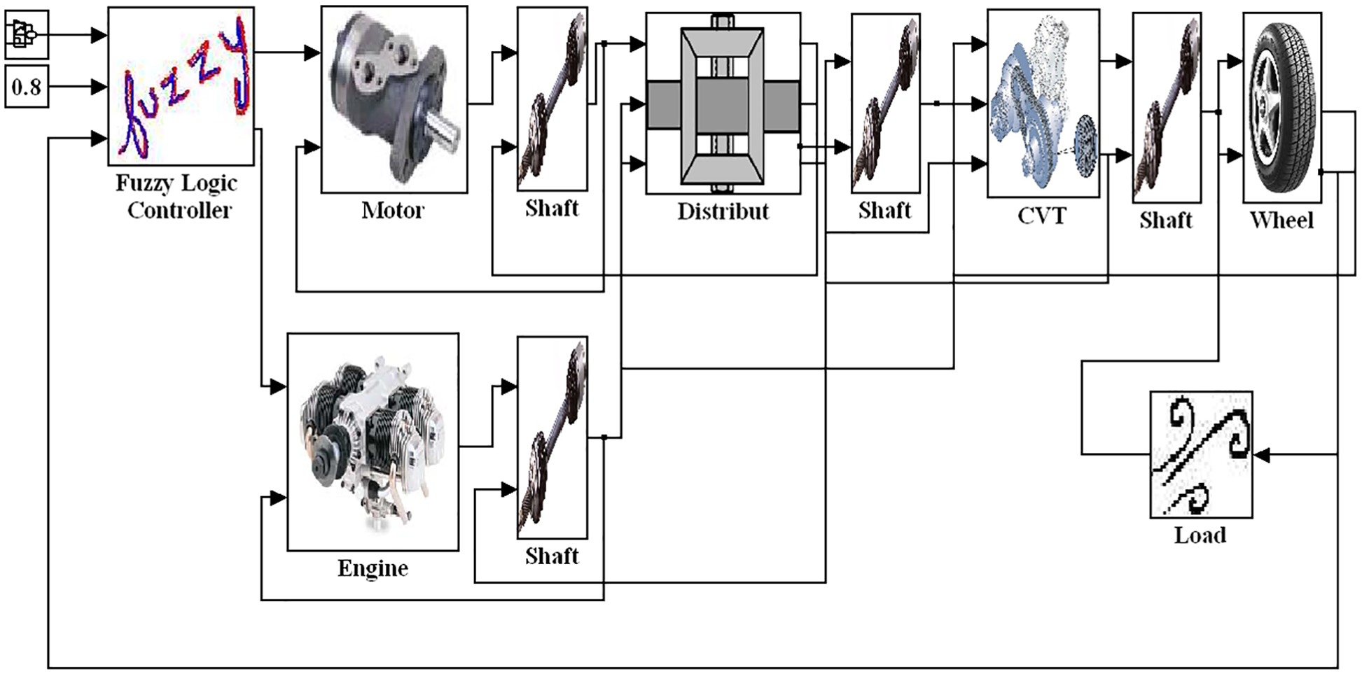
Forward simulation module of the hybrid power system.
ICE dynamic output module
The throttle position and the torque and speed of the ICE were used to establish a relative measurement look-up table. The ICE curve used in this system was based on the ICE of KYMCO DINK150. The equation is

where
PSD module
According to the linear equation (1) of the PSD of the system, the module diagram can be generated, as shown in Supplemental Material 1.
EM dynamic output module
This system uses a brushless DC motor as one of the power sources of the hybrid vehicle; the corresponding torque can be obtained from the look-up table established by its torque curve in relation to the switch position and speed of the DC motor. For the generator module, its performance was set to ∼70% of the efficiency of the EM as a reference for the simulation, and it was prevented from operating simultaneously with the EM. The equation is

where
Vehicle environmental parameter input module
Vehicle resistance is that acting on the vehicle while driving, including acceleration resistance, drag, rolling resistance, and climbing resistance. Acceleration resistance comes from the increased inertial resistance of rotating parts such as the ICE, EM, PSD, CVT, and wheel, which also accelerate as the vehicle is accelerating. The equation is

where

where

where

where

CVT dynamic module
The equation of CVT dynamic module is

where
CVT transmission shaft dynamic module
The equation of CVT transmission shaft dynamic module is
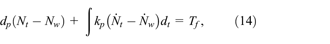
where
Wheel dynamic module
The equation of CVT transmission shaft dynamic module is

where
Fuzzy logic controller and PSD module
The construction of the module is primarily based on the pedal position of the vehicle, vehicle velocity, and SOC for power distribution such that the power of the ICE and the EM can be appropriately distributed. First, the input condition is converted into a linguistic variable expressed as a fuzzy set via a fuzzy controller; this step is known as fuzzy processing, and the input conditions are shown in Figure 5(a)–(c). Next, the algorithm developed by Mamdani assesses the input signal and then determines the output signal that should be generated. The final step is defuzzification. In this study, the center of gravity defuzzification technique is applied to map the fuzzy outputs to crisp control actions. The output conditions are shown in Figure 5(d) and (e). Figure 5(d) illustrates that the throttle position of the ICE is set to a maximum of 80%; this setting is based on the torque results of the ICE. The optimal operating range of this system is around a throttle position of 80%, a speed of 5700 rpm, and a torque of 13.1 Nm. The switch position of the EM is set to 0% to 100%. The rules in the control rule database are defined by the characteristics of the control target and desired scenarios. The diagram of whole fuzzy controller is shown in Figure 5(f), and 3D graphs of the relationships are shown in Supplemental Material 2.
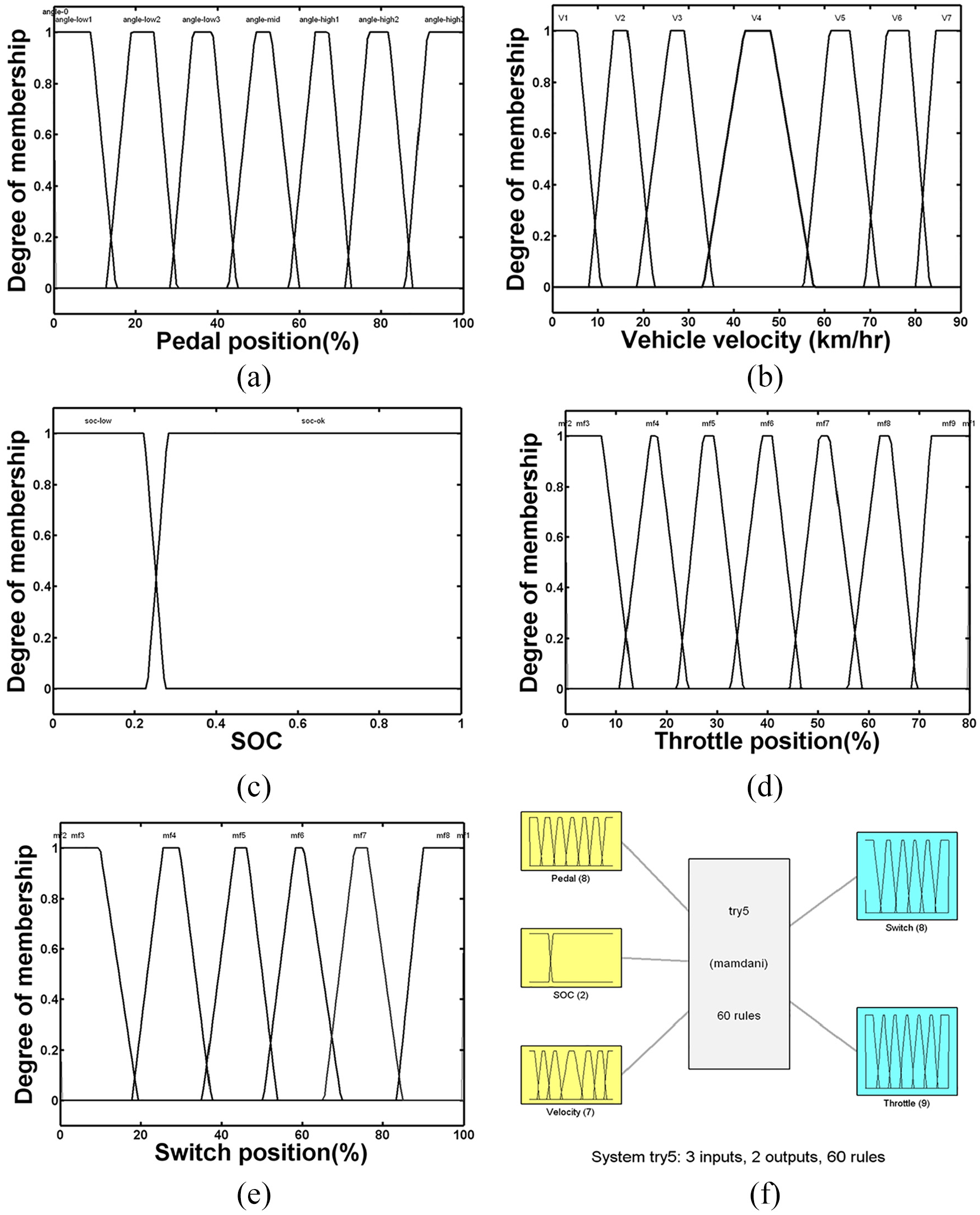
(a) Membership function of the pedal position input, (b) membership function of the vehicle velocity input, (c) membership function of the SOC input, (d) membership function of the throttle position input, (e) membership function of the switch position input, and (f) diagram of the fuzzy control.
The principle of the forward fuzzy rule database is established based on the novel energy control strategy for a parallel hybrid power system. The forward fuzzy rule database of this system can be classified into four categories:
At low-power, the EM outputs power, and the pedal position is partitioned into three regions: angle-low 1, angle-low 2, and angle-low 3. Then, different outputs of switch positions are set based on different pedal positions, following the control rules of the system.
At mid-power, the ICE outputs power, and the pedal position is partitioned into one region: angle-mid. The ICE is only partitioned into one region to maintain the ICE in the optimal operating range.
At high-power, the EM and the ICE output power simultaneously, and the pedal position is partitioned into three regions: angle-high 1, angle-high 2, and angle-high 3. At first, the ICE is maintained in a fixed position, and then different outputs of switch positions are set based on different pedal positions, following the control rules of the system.
When the battery is out of power, based on the control rules of this system, the ICE is prioritized to output power, and electrical energy is recharged by the generator.
The forward simulation of our hybrid power system applies changes in the pedal position, vehicle velocity input, and SOC to properly modulate the throttle and switch positions of the ICE and the EM with a fuzzy PSD. Based on the physical distribution principle, an ideal adjustment rule database is established to determine the power output of the ICE and the EM according to different driving conditions. The vehicle transmission parameters are divided into two parts. The rotating components include the ICE, EM, PSD, CVT, and wheels; the rotational inertia parameters are designed according to the parameters of the hybrid vehicle system of Advisor 25 and the automatic transmission control parameters in the Matlab/Simulink simulation software. The spring constant and damping coefficient in the rotating components are designed considering the overall vehicle efficiency of the hybrid vehicle. Changes to the spring constant and damping coefficient of each component alter the overall efficiency.
Results and discussion
The assembly of the experimental platform is shown in Figure 6(a), and the values of the test parameters were set as follows: The weight of the vehicle was m = 270 kg, the windward area was Al = 0.54, the drag coefficient was set to Cd = 0.43, the friction coefficient of the road was 0.018, the slope was 0°, the wheel radius was R = 0.243 m, the CVT gear ratio was 3.8 to 0.83, and the SOC was 0.8. The test specification was based on ECE 40 with modified high-speed driving at 70 km/h as the vehicle velocity input. There were four cycles in the driving pattern. The first three cycles were the same as those in ECE 40, and the fourth custom pattern was a 70 km/h cycle from 216 s to 295 s. At 216–240 s, the vehicle velocity was accelerated from 0 km/h to 70 km/h; at 240–280 s, a constant speed of 70 km/h was maintained; at 280 to 295 s, it was decelerated from 70 to 0 km/h. The driving pattern is shown in Figure 6(b).

(a) Power test platform, (b) driving pattern of ECE 40.
Torque and speed output of ICE, motor, and generator
From Figure 7, the Fuzzy logic can accurately determine the vehicle take the low-power strategy under starting and low-speed driving conditions. In this strategy, only the EM provided 13∼14 Nm of torque and 2000 to 2500 rpm during the operation time of first and second driving cycle of ECE 40. In the third driving cycle, the vehicle speed requirement match the energy strategy of med-power. Fuzzy logic could also accurately follow the driving needs, EM firstly started at the 117 s to provide 13∼14 Nm of torque and ∼2100 rpm. However, the subsequent power demand exceeds the load of EM, EM was turn off and started the ICE in 122 s to provide 13∼14 Nm of torque and 5700 rpm. When the ICE reached the predefined optimal operating range at 137 s, the system determined the torque output variation by turning on the generator to assist the ICE to overcome resistances. This allowed the ICE to remain in the optimal operating range, effectively reducing fuel consumption. During the last part of third driving cycle, the vehicle speed dropped from 50 km/hr to 32 km/hr in 155 s. Fuzzy logic judged to turn off the ICE and generator, and the EM was turned on to output 13∼14 Nm of torque and 2000 rpm until it was turned off at 176 s. The fourth driving cycle enters the high-speed driving condition, which belongs to the high-power of the energy strategy. Fuzzy logic accurately detected the driving demand and first turned on the EM at the 216 s to provide 13∼14 Nm of torque and 2200 rpm. However, the subsequent power demand exceeds the load of EM in 222 seconds. EM was shut down and started the ICE to provide 13∼14 Nm of torque and 5700 rpm. In order to maintain the ICE in the optimal operating zone and use the generator to store excess energy, the generator was started at 237 s and stop at 240 s. At 243 s, when the power output by the ICE and the EM began to converge, the operation of the device also stabilized; the ICE and the EM provided power to drive the vehicle forward until they were turned off at 280 s. However, when the EM was turned on, the ICE briefly operated outside the optimal operating range, resulting in a temporary loss of power transmission in the device. As shown in Figure 7(b), the ICE dropped from ∼5700 rpm to 4800 rpm instantaneously; nonetheless, within 3 s, the system approached equilibrium, and the power output of the EM stabilized.

(a) Torque and (b) speed output of the ICE, EM, and generator.
Torque and speed output of PSD
The power generated by the EM and ICE is transmitted to the PSD, and the torque and speed behavior is shown in Figure 8. The first and second driving cycles are driven by EM. Through the PSD, the torque can be doubled to about 26 Nm; the speed part is reduced by half to 1000 to 1250 rpm. Due to the frictional force of the device and the travel resistance of the vehicle, the torque dropped to 5 Nm after 15 s in the first driving cycle. At 54 s, because the vehicle velocity approached uniform motion, the torque decreased from ∼26 Nm to ∼6 Nm until EM stopped at 85 s in the second driving cycle. In the third driving cycle, the torque produces three waveforms. The first was generated by the EM alone and end at 122 s. The second waveform was generated by the ICE. As the ICE reached the predefined optimal operating range at 137 s, the system turned on the generator to assist the ICE to remain within the optimal operating range. Owing to the assistance from the generator, the ICE torque decreased from 13 Nm to ∼5.5 Nm. During this period of time, the speed has increased significantly, from 1000 rpm to 3000 rpm. At 156 s, the torque output by the PSD jumped to 13 Nm instantaneously. At 157 s, the power provided by the EM stabilized, and then torque of 6 Nm was maintained until it was turned off at 176 s. During this time, the speed remained stable at 1000 rpm. In the fourth driving cycle, the EM and the ICE provide torque in sequence. At 243 s, as the torque output by the ICE and EM began to converge, the operation of the device also stabilized; the ICE and EM provided ∼10 Nm power and 3750 rpm to drive the vehicle forward until they were turned off at 280 s.

(a) Torque and (b) speed output of the PSD.
Torque and speed output of CVT
The torque and speed changes of CVT are shown in Figure 9. At the beginning of the first driving cycle, 7 Nm torque was measured to the set driving mode. The torque dropped to 5 Nm after 15 s. At 23 s, because the EM stopped generating torque, the torque decreased to 1 Nm before the inertial force was depleted by the resistances. During this period, the output speed of CVT was about 400 rpm. At the beginning of the second driving cycle, 7 Nm of torque was measured to drive the car forward. At 53 s, the CVT torque increased to 8.5 Nm, which was the outcome of the CVT speed reduction ratio setting of the system. At 59 s, the vehicle velocity approached uniform motion, and thus, the torque was maintained at 6.65 Nm. At 85 s, the EM stopped providing power, and the CVT torque was reduced to ∼2 Nm before the inertial force was depleted by the resistances. The output speed of the CVT is about 850 rpm during this period. The third driving cycle was also divided into three waveforms. The first waveform is generated by the operation and shutdown of the EM. It is a slowdown waveform from 6 Nm to 3 Nm, and the speed is ∼350 rpm. The second waveform is generated by the operation of the ICE and the generator. The torque is an average of 11 Nm, and the speed is between 1200 and 1400 rpm. At 155 s, because the ICE and the generator were turned off and the EM was turned on, the CVT torque was only 3 Nm momentarily at the transition. At this time, the CVT speed dropped to 900 rpm. At 158 s, the power provided by the EM stabilized, and thus, the CVT torque was maintained at 7 Nm and the speed was 850 rpm. At the 216 s in the fourth driving cycle, the EM provides CVT about 5Nm and a speed of 380 rpm to drive the car forward until it is turned off at 222 s. At 237 s, the ICE torque reached the predefined optimal operating range, and the CVT torque increased from 4 Nm to ∼14 Nm. At 243 s, as the torque output by the ICE and EM began to converge, the operation of the device also stabilized. The CVT provided a maximum of 20 Nm to drive the vehicle forward until the vehicle reached uniform motion, and then the CVT torque decreased from 20 to 18 Nm.

(a) Torque and (b) speed output of the CVT.
Comparison of experimental results with ECE 40 driving pattern
Figure 10 presents a comparison between the driving test model and the test result. The first stage was powered by the EM: the EM started to drive the vehicle forward from 11 s and only reached 15 km/h at 23 s; this was due to the response from the system and the design of the controller. Then, because the power supply stopped, at 28 s, the vehicle velocity returned to a stationary state. At 49 s, the EM provided power to drive the vehicle to reach the second stage of the ECE 40 driving pattern of 32 km/h. It reached 32 km/h at 66 s. From 85 s, the power supply stopped, and the vehicle returned to a stationary state at 93 s. The third stage was powered by the EM and the ICE. At 117 s, the vehicle started to travel forward. At 122 s, the system determined to switch the power source by stopping the EM to allow the ICE to output power. This caused a fluctuation at 126 s due to the power switching. At 137 s, the vehicle velocity reached uniform motion; at 155 s, the ICE operation stopped, and the vehicle began to decelerate. At 156 s, the EM started to output power, and the vehicle velocity began to decrease from 50 to 32 km/h. The vehicle reached 32 km/h at 162 s. Then, the EM stopped providing power, and at 185 s, the vehicle returned to a stationary state. The fourth stage was powered by the EM and ICE, and the EM started to provide power from 216 s. At 222 s, the system switched the power source by stopping the EM and starting the ICE. This caused a fluctuation at 222 s due to the power switching. At 237 s, the system turned off the generator, and instead it switched to the EM and ICE to provide power simultaneously to drive the vehicle forward; this caused a fluctuation at 237 s due to the power switching. From 243 s, the vehicle velocity reached uniform motion. This was maintained until 280 s, when the EM and the ICE stopped outputting power and the car began to decelerate. At 292 s, the vehicle returned to a stationary state.

Comparison of the experimental result and driving test model of ECE 40.
Conclusion
In this study, an energy control system for a parallel hybrid power system was developed using dynamic equations and the fuzzy theory. The system met the requirements of various driving conditions and maintained the operation of the ICE within the optimal operating range. Based on the simulation and experimental results, the following conclusions:
Through the mechanical design, the power sources can be driven by singly or simultaneously. The design includes a one-way clutch to limit the reverse output of the ICE; therefore, a power source will not be disturbed by the other when they work separately. The two power sources can also be integrated, and the output power can double to reach the traction force required by roads.
The control strategy comprehensively addressed conditions that may be encountered during driving, such as a low SOC, a fully charged battery, and the roughness of switching between different power sources. A double-layered overlap structure was constructed to maintain the smoothness of power switching and prevent the power components from turning on and off constantly at the transition.
The torque curves of the ICE, motor, generator, and PSD demonstrated that the PSD can independently or simultaneously transmit any power source through the CVT to the wheels to drive the vehicle. The torque output by the output shaft of the PSD was also twice that of the two power sources separately.
The speed curves of the ICE, motor, generator, and PSD indicated that the speed output of the two power sources was twice that of the output shaft; this shows that the control system can integrate the speed of the two powers. The dual-energy integration device contained a one-way clutch, which prevented reverse driving of the other stationary power source.
When the demand of the vehicle exceeded the maximum output power of the EM, the PSD feature provided power from the ICE, turned on the generator, and transferred the excess energy to the generator for battery charging. When the EM started, the torque and speed of the ICE were not shifted due to a change in external resistance. This characteristic enables the ICE to operate within the optimal operating range.
Supplemental Material
sj-pdf-1-ade-10.1177_1687814020966927 – Supplemental material for Development of energy control system for parallel hybrid power system using dynamic equations and fuzzy theory
Supplemental material, sj-pdf-1-ade-10.1177_1687814020966927 for Development of energy control system for parallel hybrid power system using dynamic equations and fuzzy theory by Po-Tuan Chen, Cheng-Jung Yang and K David Huang in Advances in Mechanical Engineering
Footnotes
Appendix A
Appendix B
Handling Editor: James Baldwin
Declaration of conflicting interests
The author(s) declared no potential conflicts of interest with respect to the research, authorship, and/or publication of this article.
Funding
The author(s) received no financial support for the research, authorship, and/or publication of this article.
Supplemental material
Supplemental material for this article is available online.
References
Supplementary Material
Please find the following supplemental material available below.
For Open Access articles published under a Creative Commons License, all supplemental material carries the same license as the article it is associated with.
For non-Open Access articles published, all supplemental material carries a non-exclusive license, and permission requests for re-use of supplemental material or any part of supplemental material shall be sent directly to the copyright owner as specified in the copyright notice associated with the article.