
Abstract
Generalized cross-spring pivots (CSPs) are widely used as revolute joints in precision machinery. However, pseudo-rigid-body (PRB) models cannot capture the parasitic motions of a generalized CSP exactly under combined loads; moreover, the characteristic parameters used in PRB methods must be recomputed using optimization techniques. In this study, we develop two simple and accurate PRB models for generalized CSPs. First, a PRB method for a beam is developed based on the beam constraint model and the instantaneous center model, where the beam is modeled as two rigid links joined at a pivot via a torsion spring. Subsequently, two PRB models of the generalized CSP, comprising a four-bar model for accuracy and a pin-joint model for stiffness, are constructed based on a kinematic analysis using the proposed PRB method. A deflection characteristic analysis is then conducted to determine the relationship between the proposed model and the existing models. Finally, the PRB models for the pivot under the action of combined loads are validated via finite element analysis. The error evaluation indicates that the proposed PRB models are more accurate than the results from existing methods. The PRB models proposed here can be used in parametric design of compliant mechanisms.
Keywords
Introduction
Flexural pivots transform both motions and energies through elastic deformations. 1 These pivots are used widely in precision engineering because they offer a variety of advantages, including zero backlash, zero friction, no clearance requirements, no assembly requirements and high precision.2,3 Conventional notch-type flexural pivots exhibit high stiffness and small parasitic motions; however, these pivots experience small strokes due to stress concentration. Spring-type flexural pivots provide a wide range of motion and exhibit reduced stress because of elastic averaging effects.
The generalized cross-spring pivot (CSP)4–6 is formed by crossing two symmetrical beams at an arbitrary position (Figure 1). The CSP can be regarded as a revolute joint with fixed and moving ends. The moving end rotates around the instantaneous center, which nearly coincides with the initial intersection of the two beams for small deflections. In terms of the processing method required, generalized CSPs can be divided into monolithic and nonmonolithic configurations. 6 The nonmonolithic pivot consists of two beams located in different planes and is called the cross-axis flexural pivot (CAFP). 7 In contrast, the monolithic pivot comprises two beams located in the same plane that intersect at a virtual center and is termed the leaf-type isosceles-trapezoidal flexural pivot (LITFP). 8 Generalized CSPs can be combined to form compound pivots to achieve large strokes, small parasitic motions and quasi-constant rotational stiffness.9,10 They are commonly used in near-zero-stiffness flexural pivots, 11 precision positioning modules, 12 biaxial cartwheel hinges 13 and butterfly pivots. 14
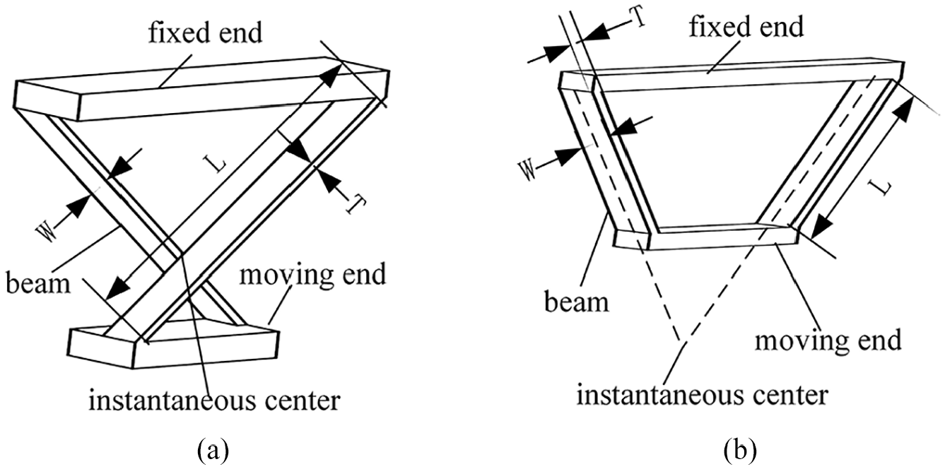
Beam-based generalized CSPs (Appendix A). (a) Nonmonolithic (CAFP) and (b) monolithic (LITFP) configurations
The distributed compliance of the generalized CSP results in parasitic motions and nonlinear stiffness performances for these pivots, particularly for large deflections. An accurate and concise parametric model can serve as an important reference for accuracy analysis and motion control. At present, the main techniques used to analyze the generalized CSP include elliptic integrals, finite element analysis (FEA), screw theory, pseudo-rigid-body (PRB) methods and the beam constraint model (BCM). 15 The nonlinear stiffness and stress characteristics of the CAFP and the LITFP were derived using a comprehensive elliptic integral; this process involved solution of complex transcendental equations.16,17 Furthermore, optimal design of the CAFP with minimal center shift and stiffness variations was investigated via nonlinear FEA. 18 A parametric model of a cylindrical CAFP was established based on the FEA results to investigate the pivot’s stiffness and stress characteristics. 19 Although the FEA approach provides high accuracy and wide applicability, it offers only limited parametric insights to designers. Screw theory was also used to analyze the center shift in terms of the instantaneous center;20,21 however, the assumption of a linear beam restricts the application of screw theory. 22
The BCM was proposed to simplify transcendental solutions obtained through polynomial approximations for intermediate deflections (i.e. < 10% of the beam length).23,24 Analytical models for the stiffnesses and center shifts of generalized CSPs were derived from the BCM within a rotation angle range of up to ±15°.4–6 However, complex load equilibrium and geometric compatibility equations have to be solved when using these models. Furthermore, a chained BCM (CBCM) 25 was used to investigate a CAFP with a contact pair in terms of its stiffness, center shift and stress characteristics and large-scale numerical calculations were required for this purpose. 7
Various PRB methods have been derived to reproduce paths for compliant mechanisms. The 1R (R: revolute) PRB model regards a cantilever beam as two rigid links joined at a revolute pivot via a torsion spring26,27 and thus achieves a trade-off between simplicity and accuracy. Chen et al. 28 and Ding et al. 29 analyzed the performances of notch-type mechanisms and optimized their structural parameters using the 1R PRB method. The PRB method can also be expanded to analyze spatial compliant mechanisms and predict their dynamic characteristics.30,31 Jensen and Howell 32 established PRB models to investigate the stiffness and stress characteristics of CAFPs using nonlinear FEA. In addition, PRB methods with multiple degrees of freedom (DOFs) were developed to enhance the accuracy of the models. The 2R PRB model, 33 the 3R PRB model, 34 the 6-DOF PRB model, 35 the dynamic spline 36 and the second-order approximation PRB model 37 were all proposed for high calculation accuracy; however, these models cannot describe axial deformation under combined loads accurately. To overcome this problem, Tang et al. 38 and Yu et al. 39 proposed the spline PRB model and the prismatic-revolute-revolute PRB model, respectively, to simulate large deflections with combined end moment and force loads. However, the characteristic parameters for these PRB methods must be determined via a numerical optimization process and these parameters must be recomputed for each different load case. Furthermore, the calculations of the deflections and parasitic motions under combined loads are complex, which caused efficiency problems for the two methods. 40 In addition, increasing the number of DOFs can realize high accuracy but can also lead to increased calculation complexity. In contrast, to avoid the need for numerical fittings, Pei et al.8,41,42 developed an analytical PRB method and used it to analyze the stiffness and accuracy characteristics of an LITFP that was subject to a pure bending moment. Verotti 43 developed a PRB method based on the Euler–Bernoulli beam equation that focused on the initial and final configurations of a deflected beam. Šalinić and Nikolić 44 proposed a 3-DOF PRB approach to modeling of notch-type flexure-hinge mechanisms. However, the total parasitic motion that occurs along a beam has not been expressed explicitly in these PRB models. In summary, the PRB methods described above cannot capture the center-shift and stiffness characteristics of generalized CSPs under the action of combined force and moment loads analytically.
The main original contribution of this article is the establishment of adaptive and analytical PRB models for the generalized CSP under the action of combined moment and force loads. The proposed PRB models are restricted to within a deformation range of 30% of the beam length. Unlike the characteristic parameters that were determined previously by using optimization solutions 32 or by ignoring the axial force,8,32,41,42 the parameters of the proposed PRB models can be obtained analytically by considering the influence of the axial force. In contrast to earlier PRB models,8,32,42 the proposed PRB models can predict the rotational stiffness and the parasitic motions of the generalized CSP when it is subjected to different combined loads. Additionally, the generalized CSP can be regarded as being equivalent to a four-bar mechanism, thus allowing the kinematic analysis techniques that are available for rigid-body mechanisms to be applied to compliant mechanisms.
The remainder of this paper is organized as follows. In Section 2, a PRB method for a fixed-guided beam under the action of combined loads is proposed based on the BCM and instantaneous center constraints. In Section 3, two PRB models are constructed for the generalized CSP through kinematic analysis using the proposed PRB method. In Section 4, deflection characteristic analysis is conducted to establish the relationship between the proposed PRB models and existing results. In Section 5, the validation of the PRB models of the pivots is presented based on nonlinear FEA results and the advantages of the proposed models when compared with the existing results are demonstrated via error evaluations. Finally, Section 6 presents the conclusions drawn from the study.
Pseudo-rigid-body method for a fixed-guided beam
To investigate the deformation characteristics of generalized CSPs, a PRB method for a beam is established based on the beam constraint model and the instantaneous center model. First, two equivalent models for a fixed-guided beam, comprising an instantaneous center model and a PRB model, are proposed. The characteristic radius factor and the equivalent stiffness factor are then derived analytically to determine the pin-joint location and the load–deflection relationship, respectively.
Equivalent model
As indicated in Figure 1, each beam in the pivots can be assumed to be a fixed-guided beam with its free end rotating around the instantaneous center.4,42 This assumption can then be used to develop parametric approximations of the deflection path.
The two equivalent models of a fixed-guided beam are shown in Figure 2. Figure 2(a) shows the instantaneous center model for a beam subjected to a bending moment M, a transverse force F and an axial force P, which result in the end displacements

Two equivalent models of a fixed-guided beam (Appendix A). (a) Instantaneous center model; (b) PRB model.
Awtar and Sen23,24 proposed the BCM for intermediate deflections (i.e., within 10% of the beam length) to describe the characteristics of a deflected beam accurately. Their BCM is described as follows:


The nondimensional parameters in equations (1) to (3) are defined as (Appendix A)

where
Characteristic coefficients for a beam.

Equation (1) represents the primary motions
Characteristic radius factor
It is necessary to solve for the characteristic radius factor


As illustrated in Figure 2(b), the deflections


For a given value of the PRB angle of
By substituting equation (7) into equation (2), the following equation is obtained:

Based on equations (4) and (7), the PRB angle can be expressed easily using the following equation:

Substitution of equation (9) into equation (8) then yields the following expression:
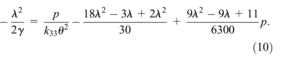
The expression for

where

Equations (11) and (12) show that the characteristic radius factor

Equation (13) has also been derived previously by Pei et al. 41 Equation (11) can capture the axial deformation without numerical optimization and is thus more adaptive than equation (13).
Consider a typical beam with the parameters

Effects of
Equivalent stiffness factor
The equivalent stiffness factor of the torsion spring determines the load–deflection relationship. Equation (3) indicates that the equivalent stiffness factor
Using equation (2), the following solution for

Combination of equations (3), (5) and (14) yields the following equation:

The first term on the right-hand side of equation (17) is of the order of
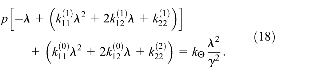
Substitution of equation (9) into equation (18) allows the solution for

For the special case where p = 0, the dimensional torsional stiffness derived from equation (19) can be reduced to (Appendix A):

Equation (20) has also been obtained previously. 41 However, equation (14) is more adaptive because it considers the axial force effect.
Using equations (14) and (15), the following expression can be formulated:

By combining equations (9) and (21), the expression for

Substitution of equation (19) into equation (22) allows the solution for

Two PRB models for the generalized CSP
Two PRB models are established for the generalized CSP under combined loads. First, an LITFP is transformed into a rigid-body mechanism using the PRB method for a beam. Subsequently, a kinematic analysis is performed to derive the four-bar model for accuracy and the pin-joint model for the stiffness.
Generalized CSP configurations
Generalized CSPs can be classified into three configurations based on the locations of their instantaneous centers (Figure 4). Two beams are arranged symmetrically about the vertical centerline and their axes cross at the intersection angle

Typical configurations of generalized CSPs. (a)
According to the Kennedy principle, the link
Kinematic analysis
The position vectors for the different configurations must all satisfy the same vector loop equations. Therefore, without loss of generality, the kinematic analysis is performed on the LITFP with

Two PRB models of the LITFP (Appendix A). (a) Four-bar model; (b) free-body diagrams; and (c) pin-joint model. The subscripts 1 and 2 refer to beams 1 and 2, respectively.
When the combined loads (i.e. the bending moment M, the horizontal force F and the vertical force P) are applied to the midpoint
Consider the free-body diagrams of the four-bar model


It can be found easily from equation (1) that

Substitution of equation (26) into equation (11) shows that the lengths of links

The vector loops shown in Figure 5(a) result in the following equations:

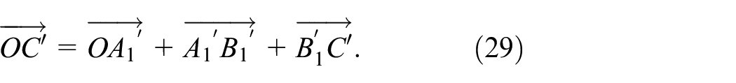
The analytical equations represented by equations (28) and (29) can be written as follows:


Equations (30) to (33) can be solved simultaneously for


Here,
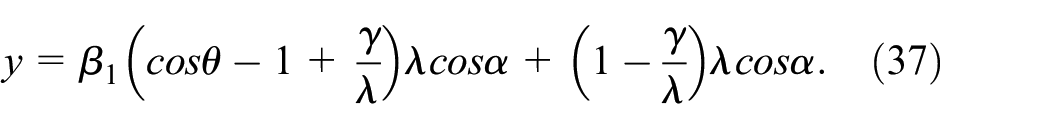
Simplification of equations (34) to (37) using a Taylor series expansion yields the following polynomial expressions:
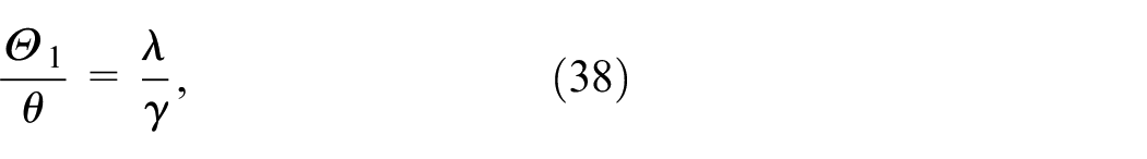


Equations (40) and (41) show that the midpoint
Four-bar model for accuracy
As shown in Figure 5(a), the center shift


Substitution of equations (36) and (37) into equations (42) and (43) allows the transcendental solution for the center shift components to be expressed as:


Consideration of the special case where p = 0 allows equations (45) and (46) to be reduced to the results obtained by Pei et al. 41
Substitution of equations (40) and (41) into equations (42) and (43) allows the polynomial solution for the center shift components to be expressed as:


According to equations (47) and (48),
Pin-joint model for stiffness
When the center shift is neglected, the four-bar model can degenerate to give the pin-joint model shown in Figure 5(c). According to the principle of virtual work, the system has a total virtual work of zero in static equilibrium:

Use of equations (19), (26) and (27) allows the equation

According to equation (50), the expression for

The four-bar model and the pin-joint model can capture the accuracy and the stiffness characteristics, respectively, of generalized CSPs under combined loads. In addition, the derivation process performs a traditional kinematic analysis rather than attempting to solve the deflection compatibility equations. The form of the expressions used here is independent of the specific value of
Deflection characteristic analysis
A deflection characteristic analysis is conducted to provide a better understanding of the relationship between the proposed model and the existing solutions. Additionally, the linear relationship between the deflections of the pivot and its beams is revealed.
Center shift analysis
The center shift of a fixed-guided beam is equal to the difference between the deflections and the instantaneous center constraints. This shift can be calculated from equations (4) to (7), as follows:

Here, the subscripts i = 1 and 2 refer to beams 1 and 2, respectively.
Comparison of equation (48) with equation (52) shows that a linear relationship between the center shift component of the generalized CSP and its beams can be derived:

The center shift of the generalized CSP in the y-direction, i.e.
Substitution of equations (11), (12), and (26) into equation (48) yields the following expression for the center shift component
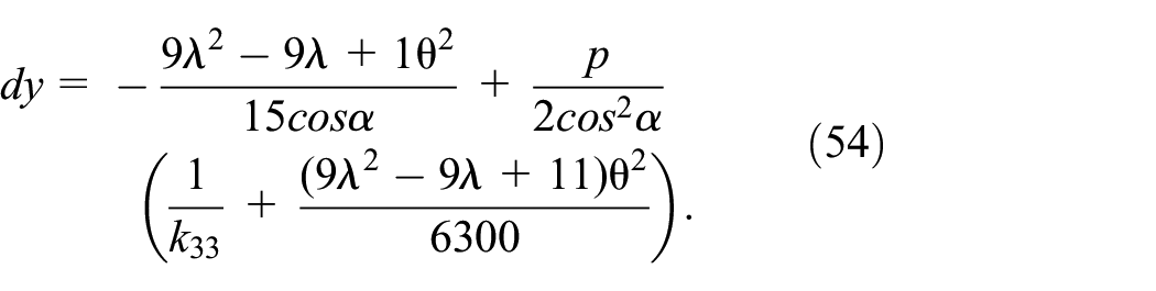
Equation (54) is consistent with the order of the result for the CAFP (
Stiffness analysis
By combining equations (22) and (51), the solution for
Equation (55) indicates that the stiffness of a generalized CSP is equal to the sum of the stiffnesses of the two beams and the load stiffening effect of the vertical force.
Substitution of equation (23) into equation (55) produces the following solution:

Equation (56) can also be obtained from the work of Zhao and Bi. 4
The rational approach to use of the deflection characteristics involves studying the effects of the various typical loads separately. The moment stiffness

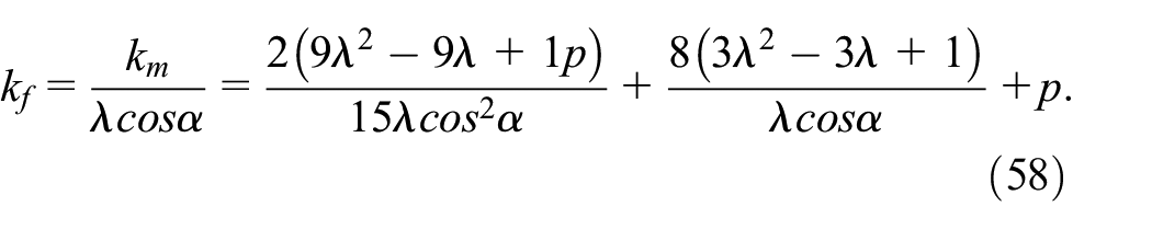
Equations (57) and (58) indicate that the moment and force stiffnesses are both proportional to the vertical force. In the case where

Equation (59) is also identical to the results obtained for the LITFP (
As mentioned above, the PRB method presented in Ref. 41, the accuracy model for the CAFP given in Ref. 42 and the pin-joint model for the LITFP and the CAFP proposed in Ref. 8 can be regarded as special loading cases of the proposed PRB models without vertical loads. It should be noted here that the accuracy model for the LITFP in Ref. 42 and the pin-joint model for the LITFP in Ref. 8 were verified experimentally, which validates the effectiveness of the proposed PRB models indirectly. The PRB models proposed herein and the results presented in Refs. 4 and 5 share certain factors because they were all derived based on the BCM. Furthermore, the relationships between the pivot and the beams can be revealed easily using the PRB models.
Model verification and error evaluation
In this section, FEA simulations and error evaluations are performed to demonstrate the effectiveness and the advantages of the proposed PRB models, respectively.
FEA verification
FEA simulations are performed to verify the proposed models of the generalized CSP using ANSYS Workbench 16.2 (Ansys Inc., Pittsburgh, PA, USA). The stiffness and accuracy characteristics of the two typical generalized CSPs listed in Table 2 are studied here. The Young’s modulus and Poisson’s ratio values are E=73 GPa and μ=0.3, respectively. The Beam188 element, which is suitable for analysis of slender beam structures, is selected for meshing in this case. The bending moment and the horizontal force are determined based on the transverse displacement with a deformation of 30% of the beam length without the application of a vertical force. The corresponding rotational angles of the CAFP and LITFP are within approximately 0.6 rad and 0.15 rad, respectively. The applied vertical load is determined by altering the compliance by 10%.
Parameters of the generalized CSPs.

Furthermore, comparisons are performed simultaneously with two other explicit models to demonstrate the advantages of the proposed PRB models. The first is a simple PRB model that was obtained using optimization methods and considers only the stiffness of the standard CAFP (
With a display magnification of 1.0, Figure 6 shows the results of total deformation simulations of the generalized CSPs when subjected to a pure moment. The moving ends of pivots 1 and 2 rotate approximately about the initial intersection point at angles of
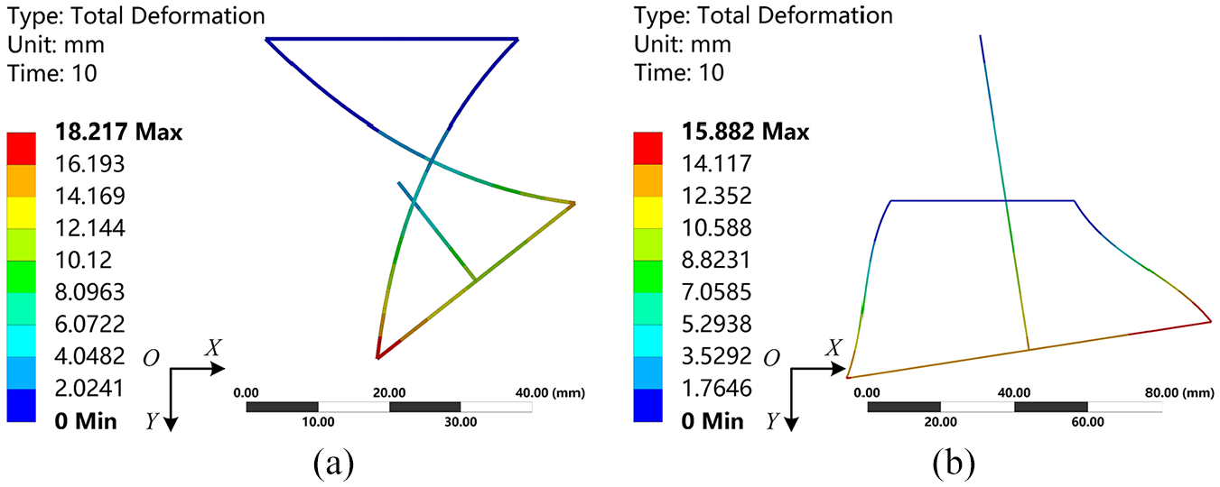
Total deformations of pivots 1 and 2 when subjected to a pure bending moment. (a) Deflected pivot 1 when subjected to a moment m=7.9701 and (b) deflected pivot 2 when subjected to a moment m=1.2681.
Figure 7 shows the rotational stiffness, which corresponds to the inverse of the slopes of the curves, for pivots 1 and 2 under the combined loads. The proposed pin-joint model mainly follows the FEA results. As stated previously, the rotational stiffness is proportional to the vertical force. A positive vertical force

Rotational stiffness characteristics for pivots 1 and 2. (a)
Figure 8 shows the center shift results, denoted by

Accuracy characteristics for pivots 1 and 2. (a)
Figures 7 and 8 show that the proposed PRB models agree reasonably well with the results of the nonlinear FEA. As noted in Section 4.2, the expressions from Refs. 4, 8 and 41 are included in the proposed PRB models. This new PRB method can capture the effects of the vertical force on the stiffness and the center shift, thus demonstrating improved applicability. In addition, the stiffness and the center shift can be either enhanced or reduced by appropriate selection of the characteristic radius factor and the external loads.
Error evaluation
The relative error is evaluated to assess the deviations between the results from the analytical models and the FEA results quantitatively, as follows:
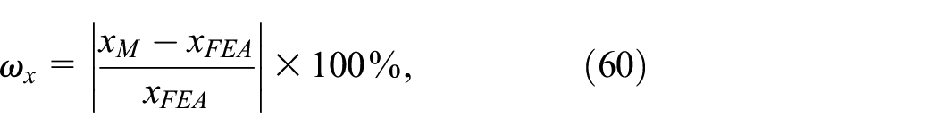
where
Figures 9 and 10 describe the maximum and average relative errors in the stiffnesses for pivots 1 and 2 under combined loads, respectively. These average and maximum errors follow the same variation tendencies. Figure 9 shows that the maximum values of all relative errors of the pin-joint model for pivots 1 and 2 are 6.0% and 9.5%, respectively. The proposed pin-joint model for the stiffness is more accurate than the previous reference model. 32 In addition, the proposed model is more efficient because it avoids use of numerical optimization methods.

Maximum relative errors in the rotational angles for pivots 1 and 2. (a) Maximum

Average relative errors in the rotational angles for pivots 1 and 2. (a) Average
Figures 11 and 12 depict the maximum and average relative errors in the center shift, respectively, for pivots 1 and 2 under combined loads. These average errors and maximum errors follow the same variation tendencies. Figure 11 shows that the maximum values of the relative errors for pivots 1 and 2 are 5.3% and 1.5% for the transcendental solution, 11.4% and 4.2% for the reference model given in Ref. 5, and 13.8% and 11.2% for the polynomial solution, respectively. The accuracies of the three models, ranked from highest to lowest, are listed as follows: the transcendental solution, the reference model, and the polynomial solution. When compared with the polynomial solution, the reference model is more accurate because the higher-order terms are retained in the latter. The transcendental solution is more accurate than the reference model, particularly for the LITFPs, because it is obtained directly from the vector loop equations. However, the polynomial solution can offer parametric insights into the deflection mechanism and can be selected to provide a balance between simplicity and accuracy during the preliminary design stage.

Maximum relative errors in the center shift for pivots 1 and 2. (a) Maximum
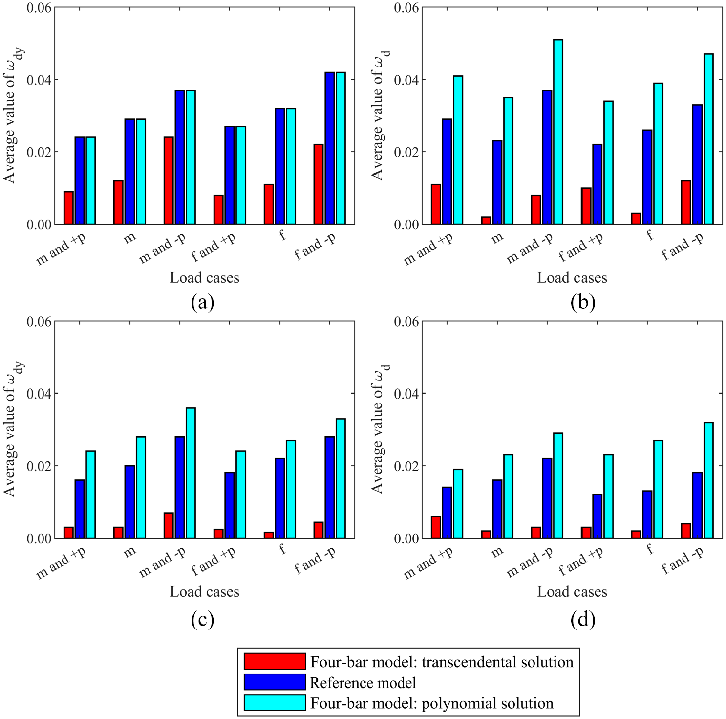
Average relative errors in the center shift for pivots 1 and 2. (a) Average
When compared with the results obtained from the existing methods, the proposed PRB models can improve both accuracy and efficiency and are adaptive to use of combined loads. These models can be applied to the analysis and synthesis of compound pivots.
Conclusions
Adaptive PRB models have been developed to enhance the efficiency and accuracy of the models used for generalized CSPs under combined loads. The main conclusions of this study are as follows. (1) The deflection characteristic analysis indicates that the existing PRB models, when ignoring the force in the DOC direction described in Refs. 8, 41 and 42, can be regarded as special loading cases of the proposed PRB models; the stiffness model in Ref. 4 is equivalent to the proposed pin-joint model; and the proposed PRB models can easily show the linear relationship between the deflections of the pivots and the beams. (2) The FEA validation indicates that the proposed PRB models can predict the rotational stiffness and parasitic motion characteristics of the generalized CSPs when subjected to different combined loads and are more adaptive than the PRB models proposed in Refs. 8, 41 and 42; the stiffness and the center shift can be either enhanced or reduced by appropriate selection of the characteristic radius factor and the external loads. (3) The error evaluation shows that the proposed PRB models can achieve higher accuracy than existing solutions. The pin-joint model is more accurate than the reference model derived using optimization methods in Ref. 32; the characteristic parameters of the proposed PRB method for a beam can be derived directly and can also be adjusted for changes in the axial load, thus improving the computational efficiency. In contrast to the analytical models presented in Ref. 5, the transcendental solution is more accurate, particularly for the LITFPs; the polynomial solution can be selected to provide a balance between simplicity and accuracy during the preliminary design stage.
This study offers an analytical PRB method for modeling of generalized CSPs that is derived directly from the BCM and the instantaneous center constraints. Additionally, this PRB method can be extended to establish PRB models for other flexural mechanisms that satisfy the instantaneous center constraints. The proposed PRB models can be used as optimization design tools for accuracy compensation and stiffness synthesis of compound pivots. For example, by considering that the stiffness and the center shift can be reduced by optimizing the characteristic radius factor, both cartwheel hinges and butterfly pivots can be constructed using the generalized CSPs in series to achieve high precision with low stiffness.
The proposed PRB models can maintain their accuracy at a deformation of 30% of the beam length. However, they are also useful for typical practical applications because the deflections in these applications are often small as a result of the stress concentrations and parasitic motions.
The goal in future work is to improve the accuracy of the proposed PRB models over larger deflection ranges by considering the effects of the horizontal force and the parasitic motions. Additional experimental research will also be performed to validate the effectiveness of the proposed models in actual applications.
Footnotes
Appendix A
Handling Editor: James Baldwin
Declaration of conflicting interests
The author(s) declared no potential conflicts of interest with respect to the research, authorship, and/or publication of this article.
Funding
The author(s) disclosed receipt of the following financial support for the research, authorship, and/or publication of this article: This study was supported by the National Key Research and Development Plan [grant number 2017YFC0110400]; and the Strategic Priority Research Program of the Chinese Academy of Sciences [grant number XDA16020704].