
Abstract
A radial thrust hydrodynamic sliding bearing (RTHSB) with special shaped cavity had been designed. Taking the instantaneous temperature rise characteristics of RTHSB as an analysis object, considering the influence of inlet lubricating oil velocity and transmission shaft speed, a dynamic simulation method of variable viscosity temperature field is proposed, and the mathematical model of instantaneous temperature rise of time-varying oil film is constructed. The correlation equation between instantaneous temperature rise and oil film variable viscosity is analyzed, the lubricating performance of a special-shaped cavity with variable thickness of the oil film considering real-time full operating conditions is revealed, and the alternating transient laws of oil film thickness with variable viscosity and its instantaneous temperature rise for no-load, heavy-load, and different rotating speeds are studied. It is obtained that the higher temperature area of profiled shaped cavity on reverse flow side extends to oil seal side with increase of rotating speed. The dynamic simulation of variable viscosity of RTHSB with different film thickness is simulated by using FLUENT software and the trend of transient film temperature field distribution of in special-shaped cavity is evaluated. The rationality of the mechanism analysis and numerical simulation results in this paper has been verified.
Keywords
Author’s Statement of Originality
We affirm that the following contents in this portfolio are the sole property of this periodical. No copies shall be made of any of its contents without permission. All of the work and samples are original and will be kept confidential by the person or company to which it is given to.
We hereby certify that we are the sole author of this thesis and that no part of this thesis has been published or submitted for publication.
We certify that, to the best of our knowledge, our thesis do not infringe upon anyone’s copyright nor violate any proprietary rights and that any ideas, techniques, quotations, or any other material from the work of other people included in our thesis, published or otherwise, are fully acknowledged in accordance with the standard referencing practices. Furthermore, to the extent that we have included copyrighted material that surpasses the bounds of fair dealing within the meaning of the China Copyright Act, we certify that we have obtained a written permission from the copyright owner(s) to include such material(s) in my thesis.
We declare that this is a true copy of our thesis, including any final revisions, as approved by our thesis committee and the Graduate Studies office, and that this thesis has not been submitted for a higher degree to any other University or Institution.
Highlights (for review)
A radial thrust hydrodynamic sliding bearing (RTHSB) with special shaped cavity was designed.
A dynamic simulation method of variable viscosity temperature field was proposed.
Mathematical model of instantaneous temperature rise of time-varying oil film was constructed.
Correlation equation between instantaneous temperature rise and variable viscosity of oil film was analyzed.
Lubrication performance of special-shaped cavity with variable oil film thickness under full working conditions was studied.
Novelty Statement
The novelty and significance of this manuscript are:
The work was studied mainly a radial thrust hydrodynamic sliding bearing (RTHSB) with special shaped cavity had been designed. A dynamic simulation method of variable viscosity temperature field had been proposed. The alternating law of variable viscosity oil film thickness and instantaneous temperature rise under empty load, heavy load, and different rotating speed are revealed. It is obtained that the high temperature region of the profiled cavity on the counter current side extends to the oil seal side with the increase of rotating speed, and the oil seal edge temperature increases with the increase of inlet velocity (the thickness of oil film is 0.05∼0.08 mm). The dynamic simulation of variable viscosity of RTHSB with different oil film thickness is simulated by using FLUENT software and the trend of transient temperature field distribution of oil film in special-shaped cavity is evaluated. The correctness of theoretical analysis and simulation results is verified by experiments.
Introduction
Optimal lubrication performance of a radial thrust hydrodynamic sliding bearing (RTHSB) is the core content of improving the high-precision manufacturing accuracy and process efficiency of modern machinery’s large load and high-precision manufacturing. The fluid instantaneous velocity in special shaped cavity changes in real time and the contact surface friction makes the oil film thick-ness or thin or thick dynamic time-varying, which affects the machining accuracy of the RTHSB and the steady viscosity and temperature characteristics for lubricating oil. The analysis of RTHSB focuses on steady state, and there is little research on time-varying transient oil film with variable viscosity. In the design of structural parameters of hydrodynamic sliding bearing, research on lubrication state, and structural parameter design of RTHSB, a simple analytical method considering effects of loaded oil pressure, oil film gap, viscosity, and input shaft speed on its displacement, was presented by Almqvist et al. 1 The hypothetical analysis model considers that the lubricating fluid in entire oil film interface area is incompressible. Based on this, the structural optimization design and performance improvement of reciprocating air compressor depends in each part on comprehensive lubrication features between the key crankshaft and its journal support bearing presented by Cho. 2 An improved hydrodynamic lubrication performance with a new star-shaped parallel slider bearings surface texture was reported by Uddin and Liu. 3 Gropper et al. 4 provided a more detailed overview of various modeling and finite element analysis for oil flow state and hydrodynamic influencing factors. Wakuda et al. 5 had determined that the porosity of the tribologically controlled surface could help reduce the friction effect at the sliding contact interface. The thrust loading pads were assumed to be deformed near the interface contact points and additional errors with different manufacturing types and amplitudes, were comprehensively considered by Zoupasa et al. 6 Wodtke et al. 7 calculated the equilibrium position of the thrust loading pad by Newton–Raphson iterative method numerical program. Thrust bearing main performance quantitative indexes (such as maximum film pressure/oil temperature and minimum film thickness/anti-friction torque) were analyzed by Lin et al. 8 Zhai et al. 9 proposed the thermoelastic hydrodynamic (TEHD) lubrication analysis of thrust bearings by combining the classic Reynolds equations and the finite element analysis (FEA) method. A large rectangular oil cushion hydrostatic thrust bearing structure was designed by Li et al., 10 and predicted its practical application lubrication performance. Based on a very detailed numerical model of aluminum foil sandwich, Lehn et al. 11 studied the air foil thrust bearings (AFTBs) performances under the conditions of alignment, deformation, and misalignment. Transient contact thermal behavior of dynamic journals and bearings during initial start-up operation was investigated by Cui et al. 12 Zouzoulas and Papadopoulos 13 performed thermal fluid dynamic lubrication calculations and studies on load-bearing types thrust bearings that exhibited different forms of surface treatments. Henry et al. 14 used an experimental analysis method to verify the thermoelastic behavior of multiple thrust bearings with a determined geometry. Through the sequential quadratic programming (SQP) method, the optimal modification of hydrodynamic film with maximum load-carrying capacity (LCC) in designed thrust bearing was given, and the cubic optimal solution of special case of the two-dimensional stepped contour region, where r had a fixed film depth (quadrilateral modification) and a constant film thickness (radial direction), were analyzed by Fesanghary and Khonsari. 15 Gao et al. 16 considered obvious differences in water/oil physical properties and analyzed the distribution rule and influence trend of eccentricity on water film pressure through computational fluid dynamics (CFD). Kim et al. 17 established a multi-objective function to optimize constraint equations of radial/axial load capacity and interface friction, contact stiffness, and damping coefficient to solve thrust hydraulic bearings with optimal load-bearing performance. Fesanghary and Khonsari 18 analyzed the optimum periodic contact interface grooves by mathematical optimization method, which launched the highest load-carrying capacity (LCC) in parallel planar bearings.
In this research project, dynamic simulation analysis method for solving time-varying law of oil film instantaneous temperature field time-varying rule for a variable viscosity RTHSB with special shaped cavity is utilized to disclosure the lubrication behaviour characteristics of special-shaped cavity with a variable oil film thickness under full working conditions in detail. What’s more, the distribution trend of transient temperature field of oil film in profiled cavity is evaluated.
Mathematical model of oil cushion for RTHSB
To the authors’ knowledge, so far, there has not been extensive research on establishing a special design as a standard for variable–viscosity RTHSB with a special shaped cavity. RTHSB configurations investigated in the present study comprise 12 oil film cushion supporting pads. The geometric configuration of special shaped cavity RTHSB, see Figure 1. With respect to RTHSBs, the answer is clear. The better temperature-pressure characteristics of radial thrust hydrodynamic sliding bearing clearly extends the working range to higher speeds and load capacity. The instantaneous variation of temperature–pressure boundary conditions has a relatively significant impact on fluid lubrication comprehensive performance of RTHSBs. The unique novelty of presented study is as follows:
A more detailed original design model for the special-shaped cavity of an RTHSB is proposed and launched.
The effect of instantaneous variation of temperature–pressure boundary conditions on fluid lubrication performance of RTHSBs is analyzed.
The relatively precise geometry of the supporting oil cushion completely explains the extension of the previous research on RTHSB. It should be noted that this study does not simulate the dynamic geometry of the oil film in more detail, but a simplified oil film stiffness model is used in this paper.
The time-varying rule of temperature field of RTHSB under different inlet flow rate and rotating speed is studied through a dynamic mesh method and the simulation results are verified by experiments.
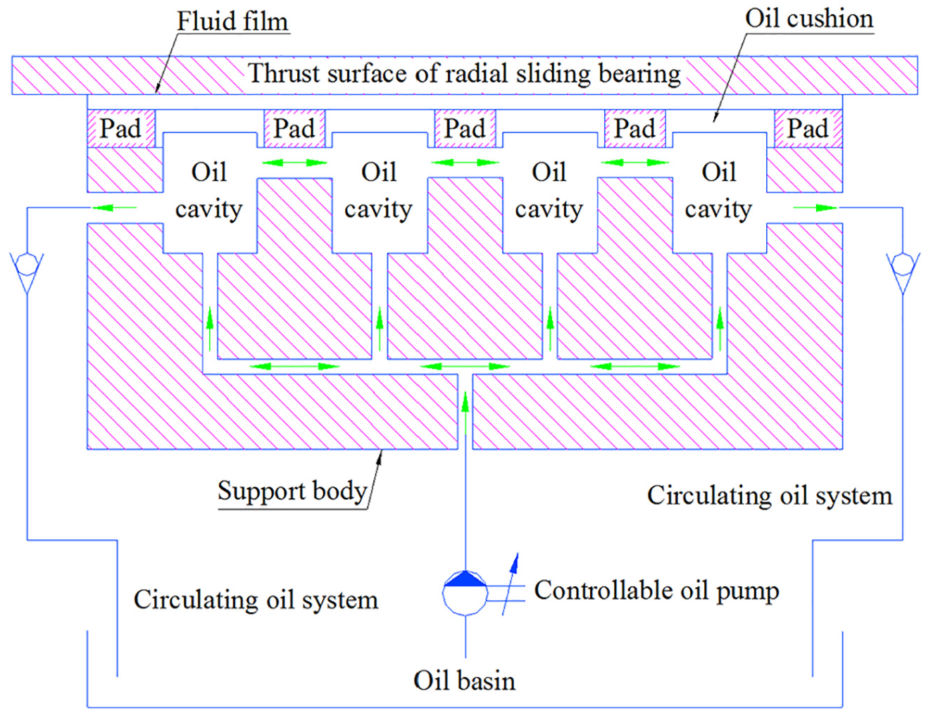
Sketch drawing of working process of an RTHSB with special-shaped cavity.
Geometric configuration of special shaped cavity
This study is organized as follows: firstly, the mathematical theoretical model, which is applicable to arbitrary RTHSBs with special-shaped cavity geometries, is briefly recapitulated. An irregular cavity model is chosen as structural model for the supporting oil pad. The smooth supporting oil pad with any shape based on the general tensor expression of the linear elasto-hydrodynamics theory is briefly analyzed. The main assumptions of the linear elasto-hydrodynamics theory are as follows:
Compared with the feature length of the contact surface of the special-shaped cavity and its minimum curvature, the pre-estimated oil film thickness is minimal. 19
Assuming that the overall film thickness on contact interface of the special-shaped cavity has been considered, the lateral shear force relative to sliding along the contact interface is constant. 20
External extensions of the thickness of inner oil pad of special-shaped cavity are neglected. 21
Based on the theory of linear elastic fluid dynamics, a numerical solution equation is proposed, which can be used for a generally smooth supporting oil cushion with a cavity structure of any shape. The governing special-shaped cavity equations are specified for a variable viscosity RTHSB geometry considered in this manuscript.
Metrical and curvature properties of a single supporting oil cushion surface
In the present work, an oil cushion 3D model for numerical simulation analysis is constructed to study the flow direction of hydraulic oil. The metrical and curvature properties of a single supporting oil cushion surface are discussed in detail. Hydraulic oil brand is set to 32#, and set the dynamic viscosity value of the hydraulic oil to 0.0435 Pa s at 30°C, see Figure 2.

3D solid model of a single-supported oil cushion for an arbitrary profiled cavity.
The preventative section of an arbitrary profiled cavity single-supported oil cushion surface F which is described by a set of convective and curvilinear coordinates


A surface metrical characteristics (a) representation of kinematics interconnection of single support oil cushion surface, (b) covariant tensor variables representation, and (c) an arbitrary cavity mathematical model description.
The oil cushion surface indicator attributes of the special-shaped cavity are described by the covariance metric tensor

The contra-variant metric tensor and the contra-variant base vectors are defined as:

where


The curvature of the oil cushion surface of the special-shaped cavity is revealed, and curvature tensor descriptions are expressed in two forms: covariant and mixed. 23


Here, in the initial configuration, a line perpendicular to the vector

Thus, the displacement field of the oil pad surface with the special-shaped cavity continuum is described by two variables


Where, a covariant differentiation is denoted by the vertical line in the index.
The moments and forces acting on an oil pad surface element

An external force vector is represented by

An internal force is expressed by

Herein,


Temperature rise equation for RTHSB considering viscosity–temperature relationship
Considering the time-varying characteristics of hydraulic oil at various temperatures, the maximum film temperature is not more than 105°C in this study, the correlation expression of hydraulic oil viscosity and its temperature is given by Sander et al. 25

Where

32# oil viscosity–temperature relationship curves.
A cross section of oil cushion for contact interface region of oil film in special-shaped cavity is a micro-rectangular element and its numerical calculation hydraulic radius (
Figure 4 illustrates that the fitting relationship between the lubricating oil viscosity and its temperature is more consistent with the data collected in the experiment when the temperature is in the range of 30°C to 120°C . Here, dynamic pattern of hydraulic oil is set to laminar flow. The density parameter (
Lubricating oil dynamic viscosity is set to

Therefore, it can be known that the Reynolds coefficient is not greater than 2320, and dynamic flow pattern of lubricating oil in oil film interface is determined as the laminar flow state.
It has been predicted that thermal behavior only causes the increase of oil film interface temperature, and the lubricating oil dynamic viscosity is transient time-varying with the temperature. Then, the shear friction power for RTHSB of the special-shaped cavity is as follows 27 :

Where

Herein,
Dynamic simulation modeling and related parameter determination
UDF programming and motion regions definition
In this article, UDF is regarded as a professional program for moving specified parts in FLUENT software. It can be seen in this model that the thrust disk in contact interface with oil film moves downward and slides relative to the shaped cavity wall, at which time the oil film interface becomes thinner. The speed at which the thrust disk slides down is expressed in
Simulation model and parameters
In ICEM&CFD software, a single oil pad geometric structure model proposed in this paper is constructed and the boundary layer mesh is refined, the periodic boundary is determined, the rotation axis and its center are defined, and the relative rotation angle is set to 30°. The boundary conditions are defined and loaded in the FLUENT numerical simulation and its numerical analysis model, as shown in Figure 5.

Geometric structure model after part generation.
A mesh encryption method is adopted to refine 10 micro blocks for a single oil cushion layer to optimize the mesh quality of the pre-specified local area and further refine it into a hexahedral mesh. The film thickness influence of 0.04 to 0.10 mm on lubricating performance is analyzed. The initial oil film thickness is set to 0.10 mm, and the outlet flow rate (Q L/min) and inlet flow rate (V m/s) are launched considering different initial boundary loading conditions. The numerical calculation results are shown in Table 1.
Preset parameters of initial film thickness (0.10 mm).

Dynamic simulation analysis of instantaneous oil film temperature field
Influence analysis of inlet flow rate on instantaneous oil film temperature field
The temperature distribution is analyzed by using the variable viscosity fluid simulation and the second order upwind method. The initial temperature is 298.6 K. An input speed of 60 rpm is given. The oil film thickness is 0.08 and 0.04 mm, respectively. The instantaneous temperature distribution and its variation trend are reflected in Figures 6 and 7.

Instantaneous oil film temperature field of special-shaped cavity oil cushion with inlet flow rate of 0.1853 m/s. (a) Oil film thickness (h = 0.08 mm). (b) Oil film thickness (h = 0.04 mm).

Instantaneous oil film temperature field of special-shaped cavity oil cushion with inlet flow rate of 0.3156 m/s. (a) Oil film thickness (h = 0.08 mm). (b) Oil film thickness (h = 0.04 mm).
The selected base planes are perpendicular to each other(X = 90 mm, Y = 906 mm, Z = 0 mm). As shown in Figure 8, the time-varying laws of oil film pressure and the transient temperature distribution trend at various points on the intersection line.

Position distribution of cross section lines.
In Figure 9, the instantaneous oil film temperature distribution trends along radial/circumferential directions are derived. The instantaneous high temperature regions of oil film are mainly distributed around the sealing ring of the special-shaped cavity. When the oil film thickness becomes thinner, the sealing ring temperature is relatively higher, and the instantaneous higher-temperature area expands along the circumferential direction and gradually deviates from its center, the instantaneous temperature of downstream side is lower than that of countercurrent side.
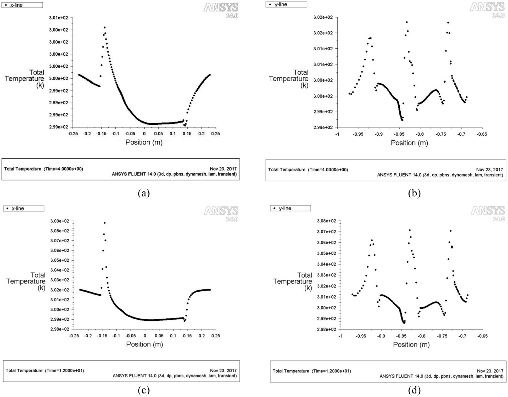
Instantaneous oil film temperature distribution along radial/circumferential directions under inlet flow rate (0.3156 m/s). (a) Circumferential instantaneous temperature distribution at oil film thickness (h = 0.08 mm). (b) Radial instantaneous temperature distribution at oil film thickness (h = 0.08 mm). (c) Circumferential instantaneous temperature distribution at oil film thickness (h = 0.04 mm). (d) Radial instantaneous temperature distribution at oil film thickness (h = 0.04 mm).
From the above analysis, it can be revealed that the diffusion is not obvious when oil film becomes thicker in low temperature area. As inlet flow rate increases, difference in instantaneous temperature magnitude between countercurrent and downstream sides becomes more and more obvious.
Effect of operating flow rate on instantaneous oil film temperature field in profiled cavity
The inlet flow rate is set to 0.3156 m/s, and film thickness values are set to 80 and 40 µm, respectively, the rotation speeds of 40 and 80 rpm are given respectively, the analysis curves are shown in Figures 10 and 11.

Instantaneous oil film temperature field with special-shaped cavity at rotating speed (40 rpm). (a) Oil film thickness (h = 0.08 mm). (b) Oil film thickness (h = 0.04 mm).

Instantaneous oil film temperature field with special-shaped cavity at rotating speed (80 rpm). (a) Oil film thickness (h = 0.08 mm). (b) Oil film thickness (h = 0.04 mm).
Instantaneous oil film temperature distribution along radial/circumferential directions at rotation speed of 40 rpm is shown in Figure 12. Here, the inlet flow rate is regarded as constant, which improves the working speed and oil film maximum temperature on the oil seal edge. The low temperature area of interface oil film in the lubricating oil storage chamber is mainly concentrated at the lower end of contact seal, while the high temperature area of interface oil film in the special-shaped cavity is mainly concentrated in the middle and lower portions of oil seal edge. The instantaneous oil film temperature on the downstream interface is not higher than that of other adjacent areas, and as the film thickness decreases, the instantaneous temperature diffusion tendency becomes more obvious.

Instantaneous oil film temperature distribution along radial/circumferential directions at rotations speed (40 rpm). (a) Circumferential instantaneous temperature distribution at oil film thickness (h = 0.08 mm). (b) Radial instantaneous temperature distribution at oil film thickness (h = 0.08 mm). (c) Circumferential instantaneous temperature distribution at oil film thickness (h = 0.04 mm). (d) Radial instantaneous temperature distribution at oil film thickness (h = 0.04 mm).
Simulation results and data analysis
The real-time transient temperature at the oil seal edge is extracted, and the distribution trend of instantaneous high temperature area of a single oil film is shown in Figure 13. The working speed is 40, 60, and 80 rpm, respectively. The relationship between instantaneous film temperature/film thickness at variable inlet flow rate is presented in Figure 14.

Oil film instantaneous high temperature region.
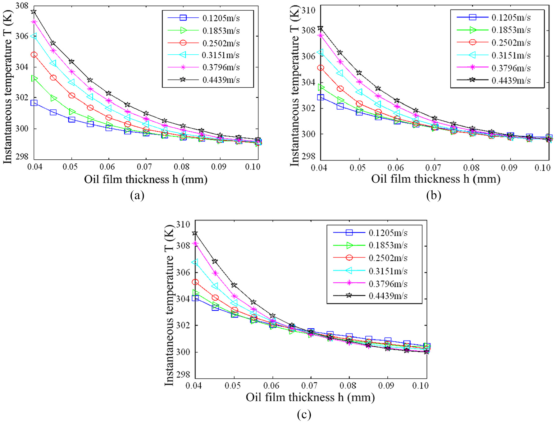
Relationship curves between oil temperature/film thickness under different inlet flow rates. (a)
In this subsection, further characterization of structural characteristics of special-shaped cavity, as a representative example, the relationship curves between instantaneous oil temperature/film thickness are described in detail. Figure 14 shows the interconnection influence of instantaneous oil temperature/film thickness. Instantaneous oil film temperature difference at inlet flow rate is not obvious, and interface oil film thickness becomes larger. The instantaneous change of inlet flow rate causes the oil pad edge temperature to increase rapidly. When the thickness of oil film is not greater than 0.07 mm, the inlet flow rate increases and the oil cushion edge temperature increases rapidly.
So far, further study shows that the initial liquid film lubrication is transformed into boundary lubrication based on lower film thickness, and the friction resistance increase of contact interface leads to significant and rapid increase of instantaneous oil film temperature in local area. High speed in operating conditions is set to 80 rpm, and film thickness is set in the range of 70 to 100 µm, when the inlet flow rate becomes smaller, the oil temperature at the contact interface of the oil pad edge is higher.
Experimental study and results analysis
Experimental details
The main experimental verification research content of this chapter is to carry out oil film thickness data analysis and oil cavity temperature monitoring. The load values of radial dynamic sliding thrust bearings are set to 0.0, 2.5, and 10.0 t, and the operating speeds are set to 20, 40, 60, 80, 100, and 120 rpm, respectively. In this verification study, a bench running test is carried out on the oil pad contact interface on the cavity by rotating motion. Usually, a load is applied to the contact interface of thrust disk during its rotation, the friction behavior generated along the tangential direction of contact interface is measured by five displacement sensors, and film thickness/oil temperature are refined through indirect conversion by calculating the friction coefficient.
The oil storage cavity material is made of GCr15 bearing steel, the thrust pad oil pad material is 45 steel, and the contact interface is provided with a special shaped recess to satisfy the oil-rich lubricating effect. The workbench material is gray iron 250 whose diameter is 4.5 m and 9.85 t in weight, and the working load had range of 0 to 32 t. 0 to 200 rpm in working speed range, the diameter parameter of oil inlet pad is designed to be 15 mm, the thickness of oil film is set to 3.0 mm, and the thrust disk surface roughness Ra is 0.05 mm to ensure that the interface friction contact is minimized as much as possible. Assuming that the thermal deformation of each part of the experimental device is ignored, only the real-time changes of oil film are considered in Figure 15.

Experimental schema of a variable viscosity RTHSB with special shaped cavity.
Experimental verification and discussion
According to the above analysis, five preset displacement sensors are arranged in oil cushion central area. The sensors arithmetic mean values with corresponding space installation location at circumferential symmetrical distribution oil film interface in special-shaped cavity are solved. The above specific sensors layout pattern and data acquisition and display are shown in Figure 16.

Sensor layout pattern and data acquisition and display. (a) Sensors layout pattern. (b) Data acquisition and display.
The rotating speed and oil temperature of the experimental platform under different working conditions are set in advance. During bench experiment operation, the radial displacements of each monitoring point are recorded to capture the required performance parameters related to oil cushion film and its initial thickness at various rotation speeds.
Experimental results and analysis
The oil cushion film thickness and temperature of special-shaped cavity under no-load, 2.5 and 10 t loads are measured under different working conditions.
Under different loads, the variation curves between oil film temperature/rotation speeds of oil cushion with a special-shaped cavity are shown in Figure 17. Analysis from the above figures, it can be seen that oil film thickness decreases as working speed increases. Considering actual conditions that the inlet flow rate is constant, the applied load becomes larger and the thickness of oil film is thinner, which is the most consistent with the previous numerical simulation results in this paper.
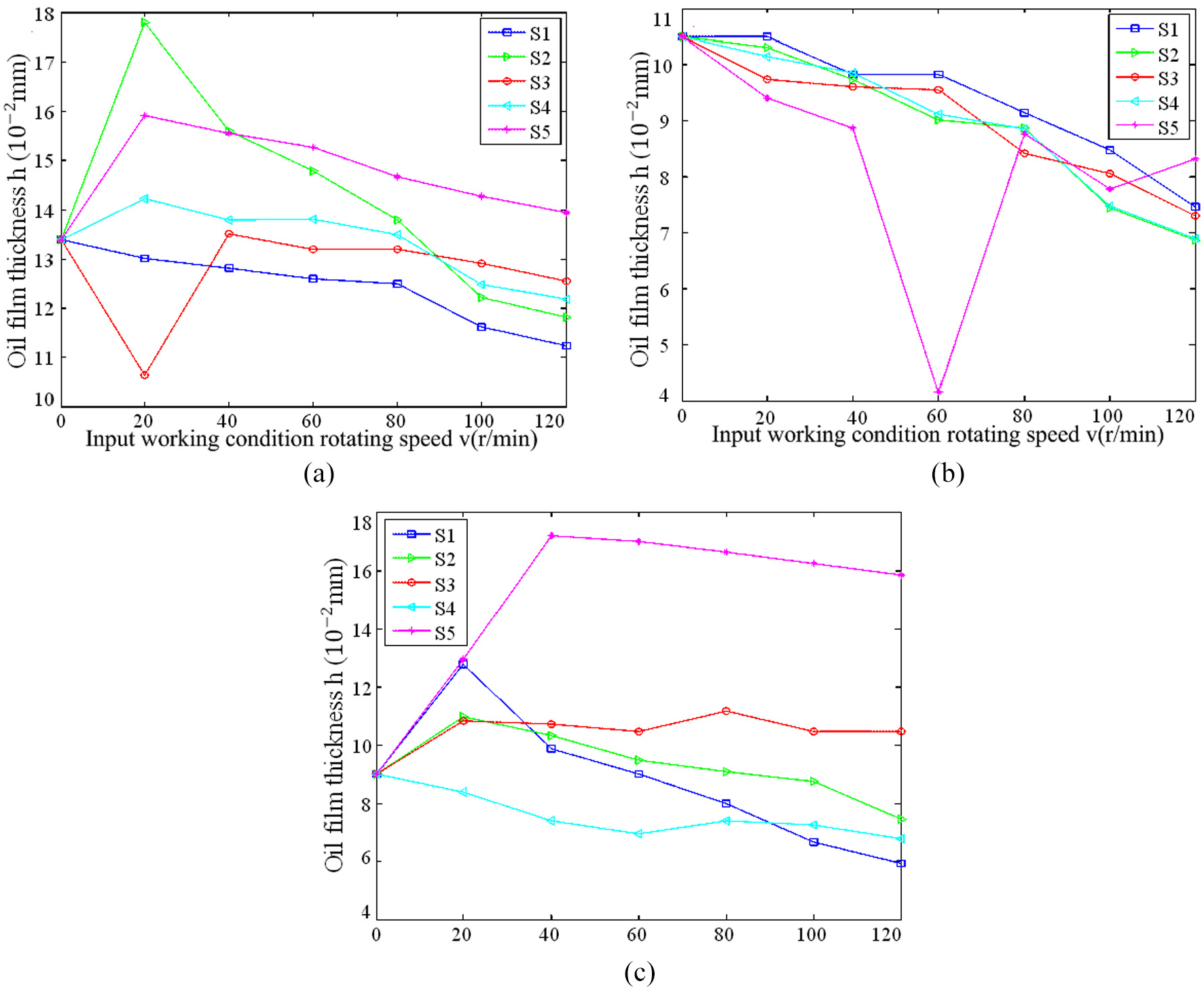
Variation curves of oil film thickness/rotation speeds under different loads. (a) W = 0 t. (b) W = 2.5 t. (c) W = 10 t.
As outlined in Figure 18, oil film interface edge temperatures on the countercurrent and the downstream sides are lower than that of oil pad. The oil pad film temperature with a special-shaped cavity is not lower when the working speed is increased. The working load is 10 t and 0.116 mm in oil film thickness. Table 2 indicates comparison results between the experimental/simulated data of oil pad instantaneous film temperature with a special-shaped cavity under different working speeds.

Variation curves of instantaneous oil film temperature/rotating speeds under different loads. (a) W = 0 t. (b) W = 2.5 t. (c) W = 10 t.
Simulation/experimental data comparison of instantaneous film temperature (unit: °C) (W < 10 t).

From Table 2, the comparison results between the experimental/simulated data are dissected. The actual instantaneous oil film temperature rise of the special-shaped cavity oil pad is almost consistent with simulation/calculation results in the case of increased working speeds. The main sources of temperature error are ambient temperature, reading error and transient temperature loss during operation of radial thrust dynamic pressure sliding bearing, and so on.
Conclusions
The surface structure parameters of oil cushion with special-shaped cavity and the influence of oil film parameters controlled by rotating speed and load are studied, and an optimal analysis model considering structural design parameters is proposed. The following novel conclusions are elaborated:
Even if the outer diameter of the best optimized design of the RTHSB becomes larger, the optimal value of oil film thickness of the corresponding oil pad will not decrease, the reason is that the optimal contact specific surface area is closely related to the structure and operation parameters.
The relation expressions of transient oil film temperature rise equations with variable viscosity/constant viscosity in a special-shaped cavity are presented. The automatic updating calculation method of dynamic mesh is constructed, and the variation rules of transient oil temperature under different film thickness distribution are revealed.
Optimum oil film thickness increases while the optimum diameter of a special-shaped cavity decreases as working speed increases and applied load decreases. In the case of an increase in inlet flow rate, the instantaneous oil film temperature rises.
At low speed, high-temperature area in special-shaped cavity is mainly concentrated on countercurrent side edge of oil pad contact interface. At high speed, the high temperature area tends to expand to both sides of contact interface edge, once oil film thickness becomes thinner, instantaneous temperature diffusion trend is obviously prominent.
The experimental verification results show that optimal design model of structural parameters with a special-shaped cavity is reasonable and effective, which provides a reliable theoretical reference for the tribological analysis of oil film interface friction of the radial thrust dynamic sliding bearing oil pad.
Footnotes
Acknowledgements
The authors who participated in the preparation of this article are very grateful for support from the Northeast Forestry University (NEFU) as well as the Heilongjiang Institute of Technology (HLJIT) and the Harbin Institute of Technology (HIT).
Handling Editor: James Baldwin
Declaration of conflicting interests
The author(s) declared no potential conflicts of interest with respect to the research, authorship, and/or publication of this article.
Funding
The author(s) disclosed receipt of the following financial support for the research, authorship, and/or publication of this article: This research topic is supported by the Special Scientific Research Funds for Forest Non-profit Industry (Grant No. 201504508) and the Youth Science Fund of Heilongjiang Institute of Technology (Grant No. 2015QJ02) and the Fundamental Research Funds for the Central Universities (Grant No. 2572016CB15).