
Abstract
In this study, the integrated MSOT (M-Multi-dimensional factor autobody model, S-Screening autobody component, O-Optimization of plate thickness, T-Testing, and validation) integration method is adopted to optimize the automobile body structure design for weight reduction. First, a multi-dimensional factor body model is established, then components of the vehicle are screened for the most important targets related to weight reduction and performance, and a multi-objective optimization is performed. Virtual experiments were carried out to validate the analysis and the MSOT method were proposed for lightweight design of the automobile body structure. A multi-dimensional performance model that considers stiffness, modality, strength, frontal offset collision, and side collision of a domestic passenger car body structure. Components affecting the weight of the vehicle were identified. Sheet metal thickness was selected as the main optimization target and a multi-objective optimization was carried out. Finally, simulations were performed on the body structure. The comprehensive performance, in terms of fatigue strength, frontal offset collision safety, and side collision safety, was verified using the optimized Pareto solution set. The results show that the established MSOT method can be used to comprehensively explore the weight reduction of the body structure, shorten the development process, and reduce development costs.
Keywords
Introduction
At present, making vehicles as lightweight as possible is an important part of automobile body structure design and has become a subject of extensive research.1–14 The automobile body accounts for about 40% of the total mass of the car; therefore, optimize the weight of the body structure can significantly reduce the overall weight of the vehicle, which can have many benefits. The weight of the vehicle structure can impact vehicle performance, for example, a lightweight car body structure design can contribute to the development of more energy efficient and environmentally friendly vehicles. Thus, the design and optimization of the automobile body structure is an important part of the vehicle design process.
For this reason, several studies have investigated methods for vehicle body design optimization. Guo et al. 15 used a modified sensitivity analysis of low-order modal parameters of the car body structure and proposed a lightweight scheme for several components of the car body. Lan and Chen 16 conducted a sensitivity analysis on a load-bearing body structure. Based on the analysis, selected several main components were used as design variables in the gradient method to optimize for weight reduction. Wang et al. 17 selected 12 metal sheet thicknesses as the design variable for a certain vehicle body structure and performed multi-disciplinary multi-objective weight reduction optimization based, balancing modality, stiffness, and side impact safety. According to side impact and noise, vibration, and hardness (NVH) performance requirements of the vehicle body structure, Wang and Lu 18 used 20 components to perform a weight reduction optimization. Wang et al. 19 selected 19 body-in-white parts based on relative sensitivity method and optimized the weight reduction with stiffness and modal constraints. Lu et al. 20 used an analytical drive design to optimize for weight reduction based on stiffness, modality, and strength of a closed body. Sun et al. used tailor rolled blank structures to reduce the weight and improve the crashworthiness simultaneously experimentally and numerically. 21 Other scholars have also contributed the field of body structure weight loss.22–27 However, since the body structure of a vehicle is a complex engineering system, the statics and dynamics, crash safety, and the influence of fatigue strength on the multidimensional performance of the system are typically considered independently. A comprehensive multi-objective design method to minimize weight is lacking and presents an urgent problem that needs to be solved.
Recently, the MSOT (M-multi-dimensional factor autobody model, S-screening autobody component, O-optimization of plate thickness, T-testing and validation) has been used widely to solve the multi-objective engineering problem. In these reports, the MSOT has been applied in motor systems and the method is efficient.28,29 In this paper, a MSOT integration method for minimizing the weight of the vehicle body structure that comprehensively considers multiple performance factors such as stiffness, modal, strength, and collision safety of the vehicle body is proposed. To develop the method, a multidimensional model of the vehicle body structure is first established and various factors are selected for the multi-objective optimization, with sheet metal thickness as the main optimization target. Then, simulations are carried out using four modules to verify the method. The method was applied to the optimal design of a domestic car body structure and the Pareto solution set was obtained, which can be used by decision makers to select the optimal solution according to preferences of the consumer.
Construction of MSOT method for comprehensive weight reduction optimization
Description of terms and modules used in MSOT method
The modules used in the method must first be defined.
Multi-dimensional factor autobody model
Multi-dimensional performance factors such as stiffness, modality, strength, and collision safety of the body structure analysis model are described and analyzed in module “M.”
Autobody screening module
The autobody screening components describe components fabricated using the hot forming process, which are selected based on the distribution law and sensitivity analysis of the body material, indicated by “S.”
Multi-objective optimization of plate thickness
The influence of the body sheet metal thickness on the body structure stiffness, modal frequency, strength, impact safety, and weight factor, etc. is analyzed, and solutions of the optimization algorithm that meet multiple objectives are derived in module “O.”
Testing and validation
The final module is used to describe the physical tests and body structure of multidimensional factors of the vehicle body model that can be used to establish virtual tests for verifying the optimization results. This is module is called “T.”
Main function of each module in the MSOT method
Since the vehicle body performance analysis is an essential part of the lightweight body structure design, various aspects are considered here, including dynamic and static characteristics, fatigue strength, and collision safety performance. Modules of the multidimensional factor body model should incorporate finite element models of the different performance indexes. Then, analyses of simulations carried out using each finite element model can be used to obtain the stress, strain, and displacement distribution nephograms of the body structure, and quantitative information about the modal stiffness, strength, and impact safety performance. In addition, the analyses provide the basis for understanding the performance of the body structure from a multi-dimensional perspective, as well as performance targets, for comprehensive optimization of the vehicle body for weight reduction. The input and output of module M are shown in Figure 1. The inputs of the optimization model are x1, x2, x3, and x4 and the outputs y1, y2, y3, and y4.
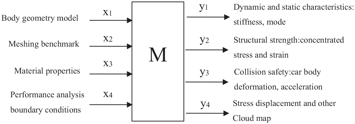
Inputs and outputs of module M.
Car bodies are composed of hundreds of components, therefore, choosing the appropriate weight-reducing components should be considered. To screen for components that contribute to a lightweight body structure, generally, we need to study force characteristics first to understand the each subsystem or component of the vehicle body from a macro perspective. Then, we can determine which components play a critical role in transmitting loads and absorbing collision energy, and which components are prone to fatigue failure. Next, the distribution stresses and strains in the vehicle body must be determined and will determine the types of material and grades that are required. Then, the stiffness and basic performance index of the vehicle body must be selected based on the layout of the vehicle body. Relative sensitivity of the bending stiffness, torsional stiffness, and modal frequency are calculated and analyzed to optimize for the thickness of the vehicle body, which is the main optimization target to minimize. The input and output of the S module is shown in Figure 2. The inputs objects are u1, u2, u3, and u4, and the output objects are outputs are f1, f2, f3, and f4.

Inputs and outputs of module S.
The thickness of the metal sheet material of the body structure will affect multiple performance targets of the vehicle and must be considered in the lightweight design. In general, there will be tradeoffs between, so it is necessary to consider how the optimization goals can be combined to achieve a satisfactory solution. The optimization process involves defining the model parameters and simulation process, the selecting the optimization algorithm and strategy, as well as many other aspects. From this point of, metal sheet thickness was selected as the optimization target. The multi-objective optimization module combines the “technical system design of experiment, approximate model, and optimization algorithm” and “objective function and constraint function, variable function,” thus thinning optimization of different intensity and metal sheet thickness. The inputs and outputs of the O module are illustrated in Figure 3. The inputs are represented by v1, v2, v3, and v4 and the output is represented by w, which is the optimal solution.

Inputs and outputs of module O.
Physical experiments are generally required to determine whether finite element models of the body stiffness, modality, strength, and collision safety used in the simulations are accurate and reliable. Typically, experimental results are compared with the finite element simulation results to validate the model. If the results are consistent, the established model can be used in the next step of the analysis; otherwise, the model should be modified before proceeding. After performing the multi-objective optimization with minimizing sheet metal thickness of the automobile body as the main optimization target, it is necessary to assess whether vehicle body performance meets requirements. To verify an improvement in performance of the optimized body structure, results of the optimization model are compared with the initial performance, which are the input and output of the T module, as shown in Figure 4. The inputs are t1, t2, t3, and t4, and the output are p1 and p2.
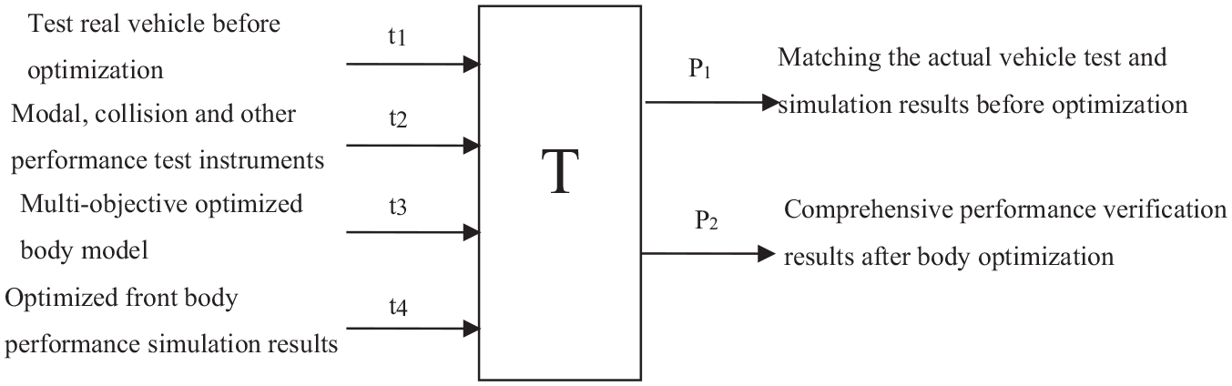
Inputs and outputs of module T.
Logical relation of each module in the MSOT method
From the above analysis of the module functions of the four aspects of the MSOT method, the relationship diagram can be obtained, as shown in Figure 5. The multi-dimensional body model (M) provides the basis for the component screening (S) and plate thickness multi-objective optimization (O). At the same time, experiments must be performed to verify the accuracy of the multi-dimensional vehicle body model. Component screening is another prerequisite for the multi-objective optimization of metal sheet thickness. Results of multi-objective optimization also need to be verified. Therefore, the multi-dimensional body model is the first module of the MSOT method, and an integrated optimization is completed along the ideal main path “M→S→O→T.” However, when the experimental result and the simulation result differ for the specific problem analysis, it is necessary to adjust the path for the following two situations to complete the integrated comprehensive optimization: (1) When the physical experiment results of the multi-dimensional body model do not coincide with the simulation results, module M inputs must to be repeatedly modified according to module T module outputs until the results are consistent; (2) When the performance of the optimized body structure does not meet requirements, the multi-objective optimization model must be modified according to T to O until the results are verified and the optimization solution meets the requirements, indicating that the comprehensive optimization is complete.
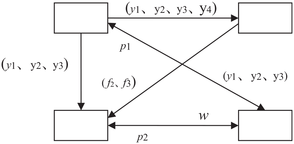
Logic relation diagram between each model in MSOT method.
Specific information about the transfer path between modules in the MSOT method is shown in Figure 5. Results of the stress distribution, upper-section force, stiffness, and modal FE models include the dynamic and static, strength, and collision safety, which are the inputs u1, u2, and u4 of module S from module M; input t4 is the vehicle body performance transferred from module M to module T; parameter p1 is the agreement between the actual vehicle test result and the simulation result, which is transferred from module T to module M; input v2 is the performance requirement of the vehicle body, transferred from module M to the module O; v1 is transferred module S to module O and represents the lightweight body target part and a thermoformed component; the optimization solution of each performance target and integrated weight reduction are transferred from module O to module T, which are represented by parameter t3; the result of the comprehensive performance verification of the vehicle body optimization is transferred from module T to module O and is represented by parameter p2.
Application of MSOT method
The established MSOT method, integration of the system, and screening of the multi-dimensional factors of body structure performance, distribution of the body material, and the screening of lightweight target parts, multi-objective optimization of the body thickness structure and experimental verification. All the steps together create an integrated and comprehensive optimization method, which can be used to effectively study the structural performance of the vehicle body and to select parts of the vehicle body that can be made thinner and lighter. In particular, for the lightweight analysis and optimization of the body structure using thermoformed high-strength steel, it has played a systematic research role.
In this method, logical relationships between structural characteristics of the vehicle body, constitutive laws of the material, the screening of lightweight target parts, multi-objective optimization of the body thickness structure, and experimental verification under the multi-dimensional factors also provide the flow of information between the paths. The method shows that a parallel engineering approach can be used as an integrated platform for optimization of the vehicle body structure design for weight reduction, enabling automation or semi-automation of data sharing and the design process.
Application of multidimensional factor body model
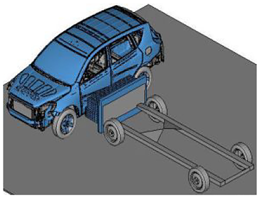
The research object of this paper is a domestic car with a wheelbase and track of 2665 and 1562 mm, respectively, and a no-load mass of 1596 kg. The stiffness, modality, strength, and positive impact, side impact, and other performance indicators of the car body in white (BIW) have an important impact on the comfort and safety of the vehicle. Finite element models of the stiffness and strength of the BIW were established using Hypermesh and structural performance analyses were carried out in MSC Nastran. The established finite element models are shown in Figures 6–9. Modeling of the BIW was based on 2D shell elements, which were used to divide each stamped sheet. The ACM contact area model was used to simulate soldered joints. The model consists of 506 components. The total number of units was 634,552, of which 568,029 are shell units and 5.5% are triangular units.

Modal analysis model.

Bending stiffness analysis model.

Torsional stiffness analysis model.
Structural strength analysis model.
Modal analysis of the BIW does not consider constraints; therefore, free boundary conditions were applied, as follows. For the bending stiffness analysis, the translational freedom of the left and right damper mounting holes in the Z direction and the rear left and right damper mounting holes in the X, Y, and Z directions, were applied in the negative Z direction to simulate the full load. The BIW model was loaded at point R of each seat according to the number of passengers and force are distributed to seat mounting points in the RBE3 unit. For torsional stiffness analysis, translation of the left and right damper mounting holes were restrained in the X, Y, and Z directions; limiting movement in the Z direction of the front left and right damper mounting holes such that translations in the Z direction are equal in magnitude and opposite in direction. A pair of couples were applied about the X axis at the front left and right damper mounting holes. For the strength analysis, translational freedom in the X, Y, and Z directions of the damper mount before restraint, X, Y, and Z translational freedom of the B subframe and body connection, C drag arm and body connection Y, Z translational freedom, rear spring seat Y, Z translational freedom, analysis of the working conditions to take the vertical impact, forward braking, turning and reverse braking limit load, the corresponding part of the weight such as the powertrain, before and after the door is replaced by a concentrated mass point.
A collision safety model was also established in Hypermesh, according to Euro NCAP regulations. The LS-DYNA software was used for the analysis. Two conditions were considered: positive and side collision. The finite element models are shown in Figures 10 and 11. The total number of elements for the first finite element model is 1432,262, consisting of 54,812 triangular units, accounting for 3.8% of the mesh. Due to the lack of a crash dummy, corresponding parts were weighted according to requirements. The total number of finite element model elements for the side impact analysis was 1393,149, consisting of 53,393 triangular units, accounting for 3.83% of the mesh.

Frontal collision analysis model.
Side collision analysis model.
In the modal analysis of BIW, the first six orders of free vibration modes were extracted. In the stiffness analysis, the Z-direction displacement and torsion angle of a series of points along the X direction of the longitudinal beam and the lower part of the sill beam were extracted, respectively, and bending stiffness and torsion stiffness of the body were obtained using the stiffness calculation formula. In the strength analysis, the stress distribution of the BIW was obtained by analyzing of each boundary condition, and the stress concentration region was extracted. The collision safety analysis considers both frontal offset and side impact. According to regulatory requirements, no part of the vehicle body structure can invade the interior of the car.
Application of component screening
For the integrated weight reduction and optimization of the BIW model, as the design variables increase, the design dimensions also increase, accordingly, and the time taken to optimize the design for weight reduction increases by a large margin. In view of this, lightweight parts are selected for the BIW, thereby shortening the development cycle and reducing costs. Since the stiffness and stiffness mode are performance characteristics of the vehicle body directly related to the strength, collision safety, and NVH performance, a sensitivity analysis based on the stiffness mode as used to determine target parts of the BIW, as shown in Figure 12.

Lightweight parts selection process.
Part screening for sensitivity analysis
The BIW finite element model has more than 500 thin-plate parts, and although symmetrical parts on the left and right are regarded as one piece, the number still exceeds 300. Reverse engineering can be used to remove parts that are clearly not suitable for modification and the rest are included in the sensitivity analysis. The types of parts to be removed mainly include the following three types.
Small parts. As shown in Figure 13, small parts occupy make up a quantity of parts with the main function of installing and reinforce other parts in the BIW, but does not bear the main load, and therefore, the potential for performance improvement is small.
Parts that cover large areas and have high dimensional tolerances and high surface quality requirements. As shown in Figure 14, these mainly include the side outer panel and top outer panel, which are difficult to mold, expensive, and have a low possibility of modification.
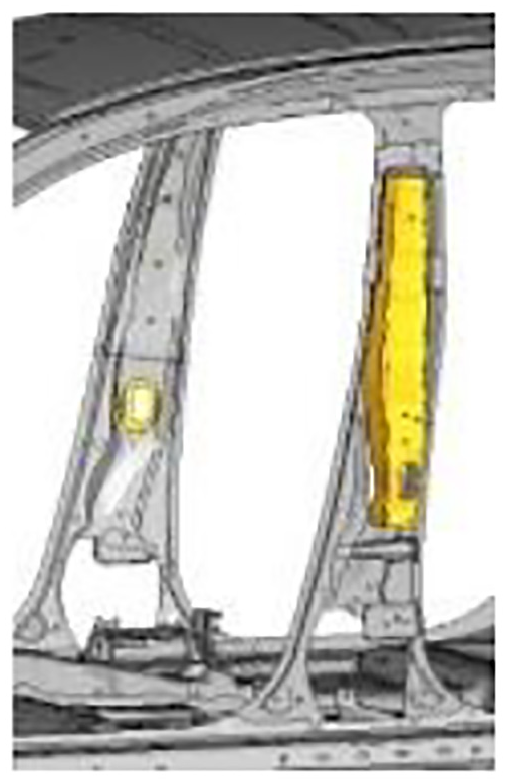
Parts that have a significant impact on crash safety. As shown in Figure 8, this includes the inner and outer plates of the energy absorbing beam and the main and auxiliary reinforcing plates of the B column. Changes would require careful handling and special experiments to verify that impact performance is maintained.
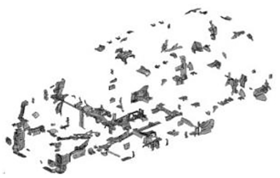
Small parts.

Side panel, outer panel, and top cover.
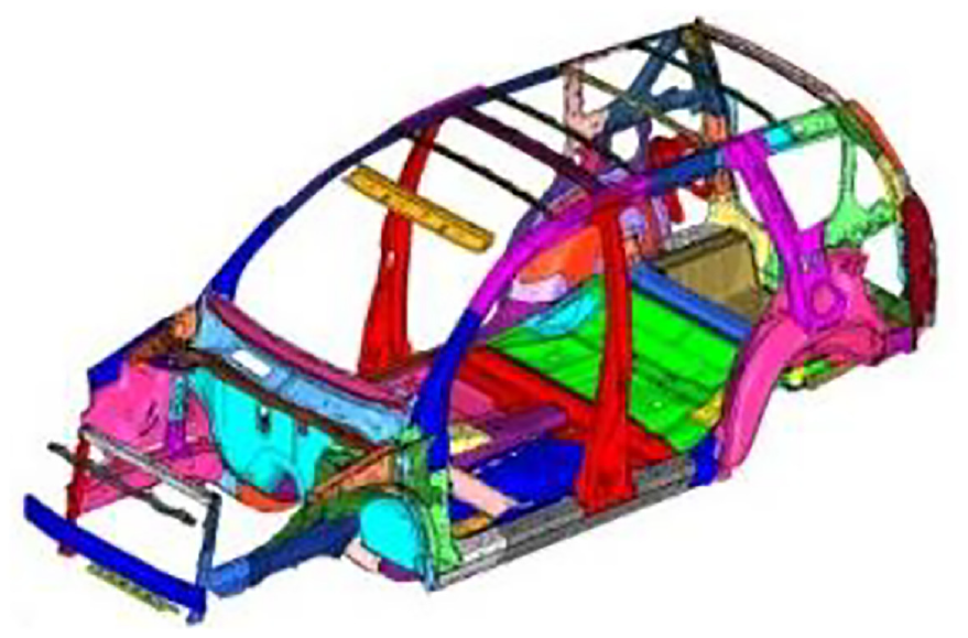
After screening, 100 potentially suitable parts were identified, as shown in Figure 15, which basically comprise components of the BIW load-bearing frame, see Figure 16 for reinforcing plates.
BIW load-bearing frame.
Reinforcing plates.
Part screening based on relative sensitivity analysis
In the body structure optimization for reducing weight, evaluating reliability, and identifying parameters, and sensitivity analysis of the structure are prerequisites. The sensitivity analysis can be based on design variables, structural parameters, structural responses, etc., depending on the purpose of the analysis. To select lightweight body part for the BIW, this paper uses relative sensitivity based on weight. The appropriate calculations can be defined as follows:


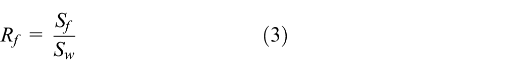
where Rb is relative sensitivity of bending stiffness, Rt is relative sensitivity of torsional stiffness, Rf is relative sensitivity of first-order modal frequency, Sb is bending stiffness sensitivity, St is torsional stiffness sensitivity, Sf is relative sensitivity of first-order modal frequency, and SW sensitivity of metal sheet thickness.
Based on the above definitions, the relative sensitivity, the sensitivity calculation, comparison and sorting of the thickness of 100 components on the screened body were obtained. In addition, bending stiffness sensitivity, torsional stiffness sensitivity, and relative sensitivity of the first-order modal frequency were ranked for the smallest 10 parts. Combined with engineering experience, 30 components were selected as optimization targets for reducing weight, including the hot-formed steel sills, anti-collision beams, and B-pillar reinforcement plates, as shown in Figure 17. Structural members are evenly distributed throughout the BIW and can better reflect the performance of the body structure. The plate variables were labeled x1∼x9 and symmetrical parts were treated as the same variable.

Lightweight object parts.
Multi-objective optimization of sheet metal thickness
Experimental design
The L81 (319) sampling test was carried out to determine the static bending stiffness, static torsional stiffness, modal frequency, and mass of the BIW using the orthogonal design method to analyze selected target parts as design variables. Design variable values of the 81 sample points in each test scheme are listed in Table 1. Response values of the corresponding body structure are listed in Table 2 where KS is bending stiffness (N/mm), KT is torsional stiffness (Nm/deg), f1∼f6 are the first six-order modal frequencies (Hz), and m is the BIW mass (kg).
Orthogonal test scheme (L81) (unit: mm).

Body structure performance response (L81).

Approximate model
For the response in the static and dynamic states, the quadratic polynomial approximation model has low accuracy. If a higher order polynomial approximation model is used for the 19 design variables with 3 levels, too many sample points will be required (about 300∼400 points), which may lead to over-fitting. Fitting at the sampling point is optimal; however, prediction accuracy is poor. Since the radial basis (RBF) prediction accuracy and stability are good, an approximate model of static bending stiffness, torsional stiffness, and modal frequency mode were established, with a Gaussian function as the kernel function. 30 Cross-validation was used to test predict the accuracy of the model. For each sample point, a RBF model other than the point was established, then the actual response was compared with the predicted value of the model at that point to verify the model. A total of 30 sample points were selected. As shown in Figure 18, static bending stiffness, torsional stiffness, and modal frequency approximation models can be obtained to predict the performance values in the static and dynamic states.
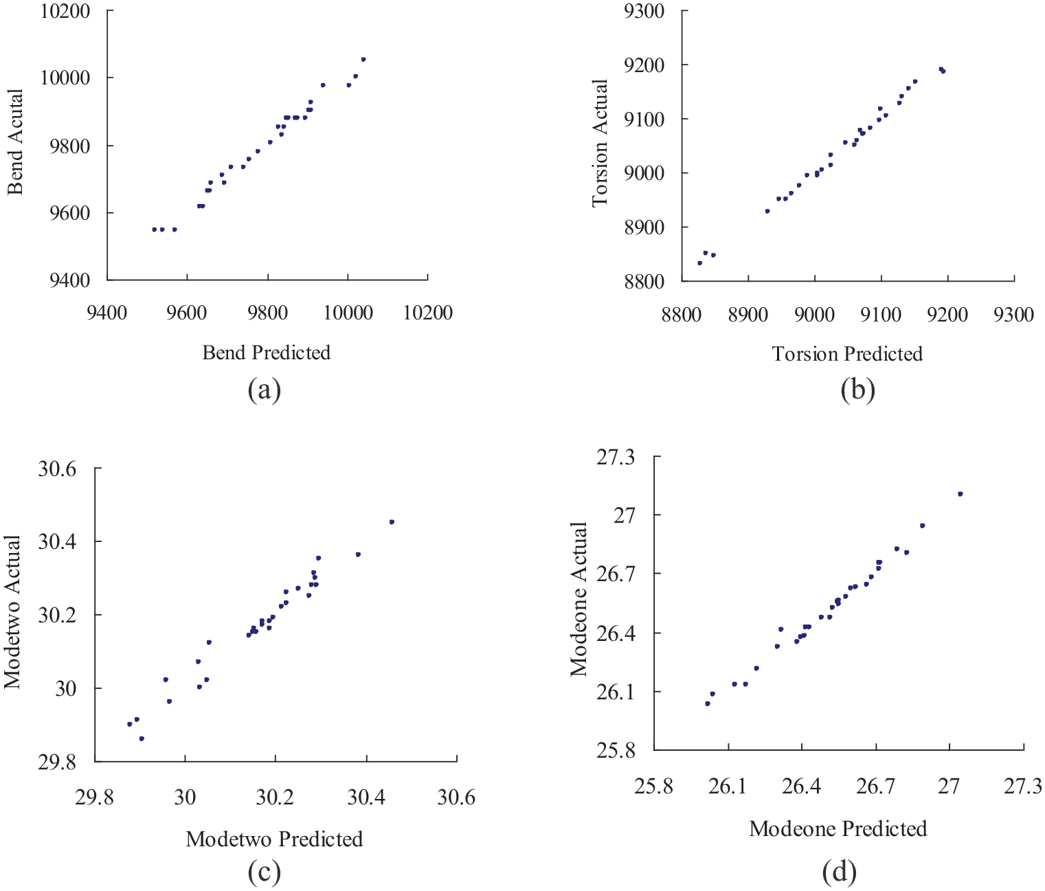
Predicted values obtained using approximate model versus actual values: (a) bending stiffness, (b) torque stiffness, (c) first-order bending frequency, and (d) top cover translation frequency.
Since the mass of sheet metal of the BIW is equal to the product of density and volume, a linear complete polynomial equation can used to establish an approximate model of the relationship between mass and thickness. Approximate response surface models of static bending stiffness, torsional stiffness, first-order bending mode frequency, and mass are presented in Figure 19 (based on the selected design parameters, only the 3D response surface diagrams of two design variables are shown).

Approximate response surface models of 19 BIW stiffness, modal and mass: (a) bending stiffness, (b) torsional stiffness, (c) first bending mode, and (d) quality of model.
Results and analysis of optimization model
According to the determined design variables, the response target and constraints are optimized, and the requirements of the weight reduction design of the vehicle body structure are taken into consideration. The mathematical model of the multi-objective optimization design problem can be expressed as:

In Equation (4), the design variable ranges from 1.5 to 2.5 mm and the all other variables range from 0.8 to 2.0 mm.
The optimization model was solved using the non-dominated sorting multi-objective genetic algorithm (NSGA-II). 31 The resulting Pareto front of the BIW mass and torsional stiffness is shown in Figure 20. It can be seen that the NSGA-II gives a variety of optimal solutions that satisfy the constraints. There is no unique optimal solution. Furthermore, the two target responses of mass and torsional stiffness are contradictory and optimal values cannot be obtained at the same time. The greater the torsional stiffness, the greater the thickness of some sheet metal parts, resulting in an increase in mass; conversely, if the body mass must be light and the thickness of some parts is reduced, the torsional stiffness will also be reduced.

Multi-objective optimization solution.
Experimental verification
Body structure modal experiment
An experimental modal measurement and analysis system was constructed using the LMS data acquisition system and software, a TIRA vibration exciter, and PCB accelerometer. A white body modal experiment of the initial physical model was carried out. As shown in Figure 21, the white body of the rubber rope suspension test adopts a multi-point excitation multi-point pick-up method, and separately excites and picks up in three directions of x, y, and z. 32
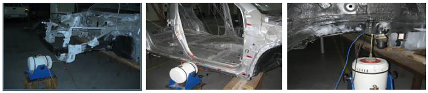
The excitation in x, y, and z direction.
The description and frequency of the first six modes and finite element analysis results measured by the BIW modal experiment are presented in Table 3. Based on the theoretical modal and experimental modal data, the natural frequency and the natural mode are of a low order. There is good consistency between results; however, the difference between natural frequencies of the second order and above is large, mainly because of simplified error, experimental error, and data processing error. In general, the finite element model of the BIW structure is feasible.
Comparison of white body modal frequency results.

Verification of fatigue strength simulation
To verify the fatigue strength performance determined by the multi-objective optimization solution, two specific schemes were adopted (denoted by stars in Figure 20). According to the load limit, fatigue strength of the white body was calculated in under the vertical loading, forward braking, reverse braking, and turning conditions, and the stress cloud of each working condition was obtained. Results of the two schemes show that stress concentrations in the white body mainly occur at the front and rear seat installation points, front and rear damper seats, and sub-frame mounting points during powertrain installation, radiator assembly installation, battery installation, and spare tire and fuel tank installation.
The initial model of the BIW and the fatigue strength analysis of the two optimization solutions are summarized in Table 4. According to the BIW analysis, when the maximum stress in a key part of the vehicle body is less than the yield limit of the material of the component under extreme working conditions, the fatigue strength is satisfied. From Table 4, the two optimization schemes exhibit weak areas of fatigue strength at the BIW installation point, which are consistent with weak areas of the initial model analysis. Under extreme working conditions, the maximum stress values are similar and far less than the yield limit of the material, therefore, the two multi-objective optimization solutions satisfy fatigue strength requirements of the BIW.
Summary of maximum stress analysis results under extreme working conditions (unit: MPa).

Verification of frontal offset collision safety simulation
To verify the frontal collision safety of the multi-objective optimization solution, two specific schemes of the optimization solution were applied to the vehicle structure for the frontal 40% deformable barrier offset collision simulation analysis, as shown in Figure 20, and the vehicle perspective initial simulation results for vehicle acceleration and intrusion were compared. The vehicle crash acceleration measurement point is located in the middle of the back door. The acceleration of the optimized two schemes and the initial model are shown in Figures 7–23. After optimization, the acceleration of the vehicle is similar to the acceleration of the initial model before optimization; however, the peak acceleration and time to peak acceleration are slightly different. For Scheme 1, the peak acceleration increases slightly, from 50.4 g before the optimization to 54.2 g afterwards, an increase of 7.56%. For Scheme 2, the peak acceleration is slightly lower, changing from 50.4 g before the optimization to 50.1 g afterwards, a reduction of 0.6%. This suggests that the change in energy absorption of the body structure before and after the multi-objective optimization are basically the same, and the load-bearing capacity of the body structure does not fluctuate significantly.

Comparison of optimization scheme and initial model vehicle acceleration.

Acceleration measured by sensor on center channel of the front seat.
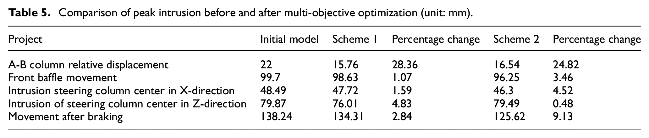
Evaluation indexes used to compare intrusion before and after the multi-objective optimization include relative displacement of column AB column, displacement of the front baffle, displacement of the steering column in the X and Z directions, and the amount of shift of the brake pedal. The intrusion evaluation indexes were optimized and are compared with initial model values of the two schemes in Table 5. After optimization, the peak intrusion value decrease by varying amounts. Overall, the frontal collision characteristics of the vehicle body structure were optimized. With hot-formed high-strength steel, intrusion of the structure was reduced and frontal collision safety was also improved.
Comparison of peak intrusion before and after multi-objective optimization (unit: mm).
Side impact safety simulation verification
To verify the side impact safety of the multi-objective optimization solution, two specific schemes of the optimization solution, as shown in Figure 20, were applied for side impact simulation analysis. The amount of intrusion, intrusion speed, and acceleration of key components are discussed and compared with the initial model simulation results.
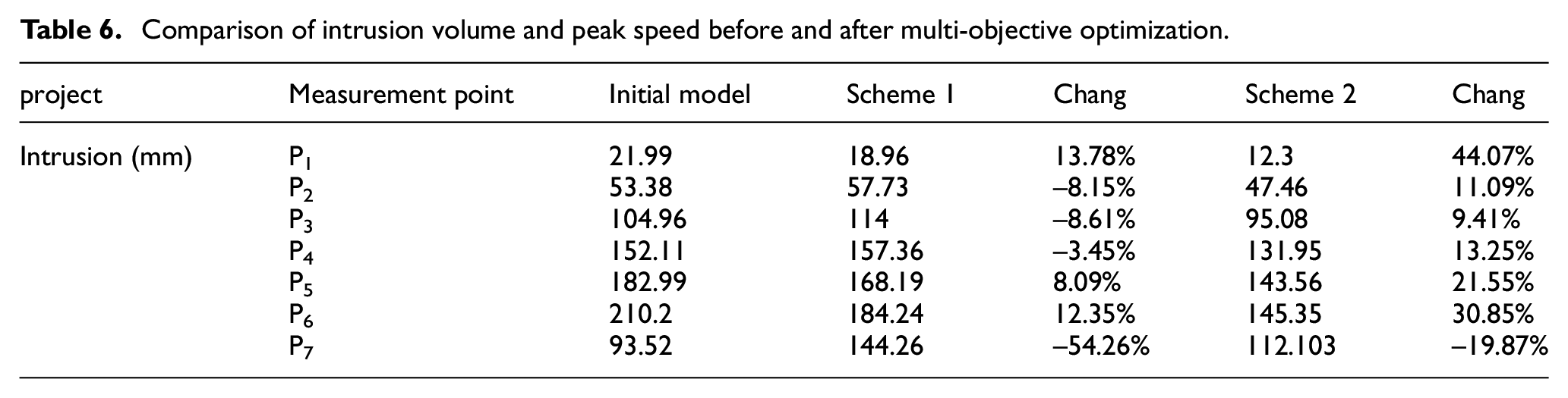
As an important evaluation index of side collision safety, intrusion of the B-pillar was analyzed. Seven nodes (referred to as P1-P7) were sequentially selected from the top to the bottom of the left B-pillar. Results of the two optimization schemes and the initial model simulation results are presented in Table 6. With the optimized schemes, intrusion of P1 and P2 at the upper end of the B-pillar is small and intrusion of P3 to P7 at the lower-middle end is large, indicating deformation at the lower end of the B-pillar is serious. Compared with the initial model, intrusion P5 and P6 is slightly decreased in Scheme 1. In Scheme 2, in addition to P7, intrusion of other points decreased to varying degrees and the maximum intrusion decreased to 12.35% and 30.85%, respectively. This suggests that the use of thermoformed high-strength steel sheets in components such as B-pillar stiffeners and sills can significantly improve the side impact resistance of the vehicle body.
Comparison of intrusion volume and peak speed before and after multi-objective optimization.
Since B-pillars and other components will bend upon side impact, sensor data were taken from above the center channel in the middle of the front seat to monitor movements during vehicle collision. Acceleration curves of the two optimized schemes and the initial model are shown in Figure 23. Acceleration of the vehicle after optimization is similar as the acceleration of the initial model before optimization; however, the peak accelerations and times are slightly different. For Scheme 1, the peak acceleration was slightly lower, reduced from 15.1 g before optimization to 139 g afterwards, a reduction of 7.95%. For Scheme 2, the peak acceleration increased slightly, from 15.1 g before optimization to 15.5 g after, an increase of 2.65%, indicating that energy absorbed by the vehicle body structure is basically the same before and after the multi-objective optimization, and the load-bearing capacity of the body structure does not appear to fluctuate significantly. However, the use of high-heat forming high-strength steel sheets in components such as B-pillars and sills can slightly reduce the peak impact force and peak acceleration during a collision.
Problem discussion and conclusions
The MSOT method was abstracted and successfully applied to domestic passenger car design in a specific automobile factory. The method was fast and effective. Based on the results of this paper, several aspects of each model should be considered.
In module M, attention should be paid to the inlet and exit parameters of the model. The body geometry model, meshing criteria, material properties, and boundary condition inputs should be used in a certain order based on the goals of the designer.
In module S, input and output parameters must be analyzed and screened by combining structural characteristics with engineering experience for each subsystem of the vehicle body.
In module O, the optimized objective function should fully consider the weight corresponding to each target, and the optimization algorithm should be selected according to the optimization target; moreover, the optimal solution set should correspond to the target market.
In module T, the parameter chosen to verify the optimization model should correspond to the test instrument and the results must be consistent and accurate; effectiveness of the optimized results should be determined based on many different aspects of the design.
Finally, based on the results of this study, the following conclusions can be summarized:
An integrated MSOT method was established based on a multi-dimensional model of the automobile body structure, component screening, multi-objective optimization of metal sheet thickness, and experimental verification of the body structure weight problem.
The MSOT method was used to build and analyze multi-dimensional performance models such as stiffness, modality, strength, frontal offset collision, and side collision models. Factors that influence weight reduction were screened and the metal sheet thickness was increased based on the optimization targets and experimental verification.
The proposed MSOT method can be used to comprehensively explore weight reduction of the vehicle body structure, shorten the development cycle, and reduce development costs.
Footnotes
Handling Editor: James Baldwin
Funding
The author(s) disclosed receipt of the following financial support for the research, authorship, and/or publication of this article: This paper is supported by the construction project of the electric vehicle scientific research basic innovation platform of Foshan Science and Technology Bureau of Guangdong Province (No. 2014AG10012). Meanwhile, the work is supported by Key Laboratory of Lightweight and high strength structural materials of Jiangxi Province (No. 20171BCD40003).
Declaration of conflicting interests
The author(s) declared no potential conflicts of interest with respect to the research, authorship, and/or publication of this article.