
Abstract
The rapid development of low-power electronic sensors and integrated circuits has made the energy supply module complex and costly to a greater extent. The traditional energy supply method is based on external wiring or built-in batteries, which gives rise to a series of problems such as high costs of installation and maintenance, and environmental pollution. Mini-type energy generators absorb the ambient energy to power wireless devices, which is a promising energy supplying method. This method has the advantage of low installation cost and battery-free maintenance. This study proposed a digital design of a Step-type electromagnetic energy harvesting device. Two design goals should be considered to make the energy generator work well. First, the pedal can drive the energy generator to generate electricity during the stepping and rebounding process. Second, the pedal should have a small pedaling displacement, so as not to affect the normal walking state of pedestrians. To achieve the above goals, this research designed a compliant lever structure with elastic energy storage function and displacement amplification function. The pseudo-rigid body model is used to conceptually design the flexible mechanism. The electromagnetic force of the iron core at different positions is calculated by simulation analysis and verified by experiments. Based on these results, this device can be used effectively as a monitoring system host node at the doorways of hospital wards.
Introduction
With a rapid increase in the aging population and the growing patient management cost of the hospitals, the need to use the wireless sensor network (WSN) technology to realize the positioning and monitoring of people is becoming inevitable for public buildings to improve the quality of healthcare and build modern intelligent hospitals. Complex wireless sensor networks require separate battery supplies or relatively a complex system wiring. To reduce the high costs of installation and maintenance, and environmental pollution, mini-type energy generators have been introduced to supply the wireless node systems.1–3
There are five categories of mini-type energy generators: solar generators, thermoelectric generators, piezoelectric generators, radio frequency (RF) generators, and electromagnetic generators.1–3 Solar generators need a consistent source of stable sunlight, and thermoelectric generators that are based on the principle of See-beck effect need constant temperature gradient. Both devices are heavily dependent on the environment.1,2,4,5 Piezoelectric generators are designed typically in the form of cantilever beams to reduce their natural frequencies.3,6,7 These generators are only suitable for operation in a stable vibration environment with a narrow frequency band. The RF generators can conveniently utilize the electromagnetic radiation of the surrounding environment. However, since the attenuation of electromagnetic radiation increases as the transmission distance increases, the output power of the RF generators is less than other energy harvesting devices.1,2,4 The electromagnetic mini-type generators generate electricity based on Faraday’s law. These generators have simpler structures than linear and rotary motor and can be intended to generate electricity by harvesting energy from impact loads.8–10 Several studies and experiments have been done to investigate the level of energy collected in the ambient. The ambient light energy density under a direct sunlight condition is hundreds of times the ambient light energy density under typical artificial lighting conditions. In the long run, environmental RF energy is an ideal indoor self-energy solution, but there is a contradiction between transmission distance and efficiency, and the impact of RF energy transmission on human health needs to be seriously evaluated before being applied to public places. 11
An electromagnetic energy harvesting pedal, capable of absorbing the pedaling impact of the monitored person and converting it into electrical energy, was designed. The human pedaling force is a typical low-frequency impact load. These electromagnetic generators can be installed at the entrance of hospital wards or integrated in the shoes and can conveniently utilize human mechanical energy to monitor work. A neodymium magnet which also known as NdFeB, is a permanent magnet made from an alloy of neodymium, iron and boron to form the Nd2Fe14B tetragonal crystalline structure. The NdFeB magnet is a strongest type of permanent magnet, available commercially. It is an ideal material to design mini-type electromagnetic energy harvesting devices. In this study, NdFeB permanent magnetic material was used to design the device and consisted of two C-type stator circuits with pure iron material. The magnitude of the magnetic flux density passing through the induction coil was changed by moving an iron wound around the induction coil. This change in the magnitude of the magnetic flux induced a current. The pedals were rebounded using a magnetic spring. An energy generator needs a power unit to convert the collected energy into electricity that can be used by the load.
Concept design
Structure diagram
The structure of the electromagnetic energy generator pedal is shown in Figure 1(a). It consists of a top pedal, compliant lever energy storage structure, inductive winding coil, guideways, a magnetic spring, and upper and lower magnetic loops. The permanent magnet and the iron core constitute the top and base C-type loop of the magnetic field circuits. When pedestrian steps on the pedal, the pedal is triggered. The energy generator converts human mechanical energy into electrical energy. The test model is shown in Figure 1(b).

The structure of the electromagnetic energy generator pedal.
Working principle
The working principle of the electromagnetic energy generator is shown in Figure 7. During the stepping and rebounding processes, the direction of the magnetic induction in the coil core changes twice, thereby converting the impact load portion into electrical energy. To ensure proper operation of the pedal, two design goals should be considered. First, the pedal can drive the energy harvester to generate electricity during the stepping and rebounding process. Second, the pedal should have a small pedaling displacement, so as not to affect the normal walking state of pedestrians. To achieve the above goals, this research designed a compliant lever structure with elastic energy storage function and displacement amplification function. The pseudo-rigid body model of the structure is shown in Figure 2.
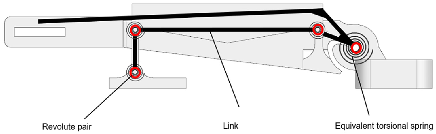
The pseudo-rigid body model of the structure.
Simulation and experiment method
Simulation method
ANSYS Maxwell (Student Edition) is an electromagnetic field simulation software. 12 It is a powerful general electromagnetic field analysis tool used to design and analyze electric motors, actuators, sensors, transformers, and other electromagnetic devices. ANSYS Maxwell is based on Maxwell’s differential equations, which uses finite element methods to transform the calculation of electromagnetic field problems in actual engineering into matrix equations that can be solved numerically. This study mainly used the 3-D magnetic field module of the Maxwell software to analyze the magnetic field force of the moving iron coil and the magnetic flux through the coil. Figure 3 and Table 1 show the parameters needed for calculation.
Parameters of the materials used in Maxwell magnetic simulation.

Due to insufficient magnetization, Magnetic Coercivity is value after being calibrated by Gauss meter.
The relationship between the magnetic field strength,

B-H curve of steel 1008.
Ansys workbench is used for structure-related simulation. The properties of the polymer materials used in the simulation are shown in Table 2. The geometric nonlinearity of the model needs to be considered in the simulation.
Parameters of the material used in Ansys workbench.

Experiment devices
The experimental equipment used in this research is as follows: NI cDAQ-9174 data acquisition equipment, NI 9871 force measurement bridge module, NI9211 analog signal input module produced by National Instruments. The laser sensor is OD5-85T20 produced by Sick, the repeatability of the sensor is 1 um. The low-range load sensor type is SUMM-10 K produced by SENSTECH, with a capacity of 10 kgf, the output sensitivity is 0.788 mV/V. The high-range load sensor is FlexiForce A401 Sensor produced by Tekscan, with a standard Force of 4448 N, the Linearity is less than 3%. The data acquisition software uses LabView 2019 produced by National Instruments.
Experiment method
The pedal is designed to amplify the input displacement and drive the iron core to work through a flexible lever structure. It also can provide sufficient driving force and rebound force to drive the coil iron core to work. To achieve the design goal, it is necessary to accurately measure and calculate the magnetic force acting on the iron core during the working process. The test device shown in Figure 2 is designed to test the magnetic force of the C-shaped magnetic circuit on the core. A worm gear linear guide with a micrometer is used to control the feed displacement during the test. A SUMM-10K sensor is used to measure the applied force. To ensure the measurement accuracy, two laser sensors are used to measure the precise displacement of the C-shaped magnetic circuit and the iron core respectively.
The FlexiForce sensor series produced by Tekscan is a piezoresistive sensor which is suitable for load measurement in coaxial structures. This research integrates the FlexiForce 401 sensor into the pedal. Because the sensor has obvious nonlinear output characteristics, the sensor needs to be calibrated. Use the device shown in Figure 3 for sensor calibration.
In a similar way, the rigidity of the flexible lever device, the displacement amplification factor and the parameters of the energy generator are measured in different static equilibrium positions. The measuring device and approach are shown in Figure 4.

Test device for measure the magnetic force acting on the iron core during the working process.
See Figure 5 for Calibration of piezoresistive sensor and see Figure 6 for Energy harvester quasi-static process parameter measurement

Calibration of piezoresistive sensor.

Energy harvester quasi-static process parameter measurement: (a) stiffness measurement of compliant lever structure, and (b) energy generator parameter measurement in different static equilibrium positions.
Results and discussion
Experiment method
Figure 7 shows the change in the magnitude and direction of the magnetic flux as the position changes.
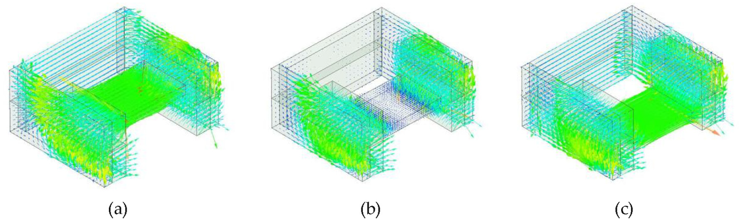
The direction of the magnetic induction line inside the iron core: (a) up position, (b) middle position, and (c) down position.
Figure 8 shows the simulation results and test results of the magnetic field force on the iron core. It can be seen from the figure that the two are basically the same trend.
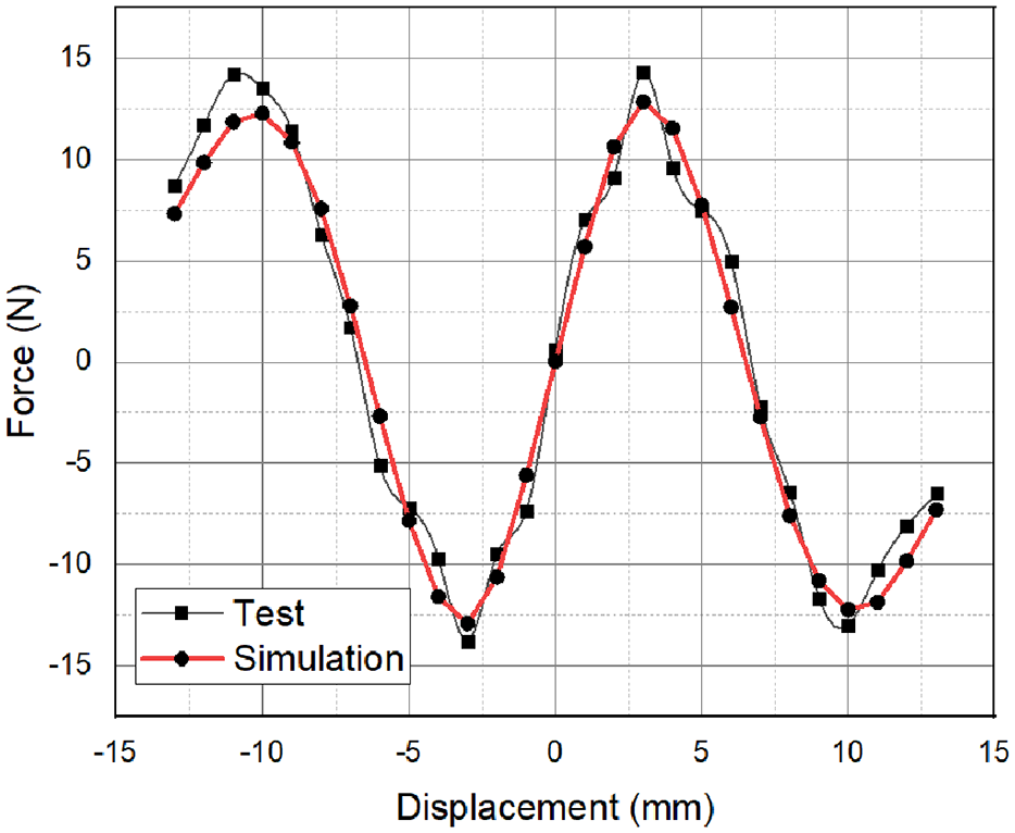
The simulated magnetic result and the experimental magnetic field result at different positions.
Table 2 shows the stiffness of the flexible lever mechanism in different directions.
See Table 3 for Linear stiffness of iron core in Cartesian coordinate system
Linear stiffness of iron core in Cartesian coordinate system.

Figure 9 shows the deformation, stress distribution and strain energy distribution at the moment of maximum force during the transient simulation analysis.

The structure of the electromagnetic energy generator pedal: (a) deformation, (b) stress, and (c) strain energy.
See Table 4 for Partial experimental parameters used in experiment and Maxwell magnetic simulation
Partial experimental parameters used in experiment and Maxwell magnetic simulation.

The induced electromotive force generated by the electromagnetic power generation device was measured using an oscilloscope. The internal resistance of the oscilloscope probe was 10 MΩ, which was much larger than the coil internal resistance. The sampling frequency of the oscilloscope is 500 Hz.The energy generator pedal was stepped for 50 times, and the induced electromotive force generated by the oscilloscope was measured, and the experimental results were averaged to obtain the result as Figure 10.

Impact force and open circuit voltage in step progress.
Conclusion
The purpose of this study was to design an electromagnetic power generation pedal device, based on NdFeB magnet. This study proposed a digital design of a Step-type electromagnetic energy harvesting device. Two design goals should be considered to make the energy generator work well. First, the pedal can drive the energy generator to generate electricity during the stepping and rebounding process. Second, the pedal should have a small pedaling displacement, so as not to affect the normal walking state of pedestrians. To achieve the above goals, this research designed a compliant lever structure with elastic energy storage function and displacement amplification function. The pseudo-rigid body model is used to conceptually design the flexible mechanism. The electromagnetic force of the iron core at different positions is calculated by simulation analysis and verified by experiments. According to the magnitude of the electromagnetic force, a reasonable lever and energy storage mechanism are designed so that the displacement of the energy harvesting input end and the mover core meets the design requirements and is verified by experiments. Finally, the power generation capacity test under the pedaling state is carried out. The test results show that the device meets the original design requirements.
Footnotes
Handling Editor: James Baldwin
Declaration of conflicting interests
The author(s) declared no potential conflicts of interest with respect to the research, authorship, and/or publication of this article.
Funding
The author(s) disclosed receipt of the following financial support for the research, authorship, and/or publication of this article: This work was supported by Korea Institute of Advancement of Technology (KIAT) grant funded by the Korea Government (MOTIE) (P0012769, Human Resource Development Program for Industrial Innovation).