
Abstract
The objective of this work is to evaluate the effect of residual thermal stresses, arising after assembling a single-lap joint at elevated temperature, on the inelastic thermo-mechanical stress state in the adhesive layer. The numerical analysis (FEM) employing linear and non-linear material models, with geometrical nonlinearity accounted for, is carried out. Simulating the mechanical response, the calculated thermal stresses are assigned as initial conditions to polymeric, composite and metallic joint members to reflect the loading sequence where the mechanical strain is applied to cooled-down structure. It is shown that the sequence of application matters and simulations with simultaneous application of temperature and strain give different result. Two scenarios for adhesive joints with composites are studied: joining by adhesive curing of already cured composite parts (two-step process) and curing the adhesive and the composite simultaneously in one-step (co-curing). Results show that while in-plane stresses in the adhesive are higher, the peaks of out-of-plane shear stress and peel stress (most responsible for the joint failure) at the end of the overlap are reduced due to thermal effects. In joints containing composite parts, the one-step joining scenario is more favorable than the two-step. The ply stacking sequence in the composite has significant effect on stress concentrations as well as on the plateau value of the shear stress in the adhesive.
Keywords
Introduction
In order to reduce the weight and fuel consumption in aerospace and automotive applications, composite materials have been widely used in modern manufacturing1,2 instead of metals. For example, fuel consumption in Boeing 787 was reduced by 20% due to decrease of the weight by 50% achieved by use of composites, and in Airbus A380 the energy consumption was reduced by 12% as a result of use of 25% carbon fiber reinforced plastic (CFRP) in weight of the structure. 3 These trends to build hybrid structures (metal and composites) will continue and more metal parts will be substituted by composites in the future. Unavoidably, these different materials have to be joined together, so there will be numerous joints within the structure between similar and dissimilar material (e.g. composite-composite and composite-metal). Typically, three types of joints are considered: adhesive joint, mechanical joint or combination (hybrid) of both of them. 4 The adhesive bonding has unique advantages in comparison to traditional mechanical connection, they are lighter and the joint fatigue life is improved, 5 the stress distribution in the bonding area is more uniform, 6 better resistance to environmental effects like corrosion is achieved. 7 One of the main problems concerning replacement of mechanical joint by adhesive bonding is the residual thermal stresses due to joining process of similar and dissimilar materials at elevated temperatures. The residual thermal stresses arise because of mismatch of thermal expansion coefficients between the adherends and the adhesive. Moreover, the composite laminates are usually produced at elevated temperature which causes residual thermal stresses within the laminate itself (e.g. in plies with different fiber orientation within multi-axial laminate) that may have a significant impact on joint strength. Sometimes these stresses are high enough to cause failure within the laminate layers even before any mechanical load is applied. 8
There are a number of studies where residual thermal stresses in adhesive joints with composite adherends are accounted for. These studies3,9,10 were carried out on the single-lap joint (SLJ) with similar and dissimilar adherends. Experimental data and results of a numerical model to predict the residual thermal stresses in dissimilar (CFRP/aluminum) adhesively bonded SLJs are presented. 3 As expected, the residual thermal stresses are higher if curing temperature is increased, at the same time the thermal stresses (Von Mises stress) in adherends (aluminum and CFRP) are higher than in the adhesive layer. This results in compressive stress in the CFRP and tensile stresses in the adhesive layer as well as in the aluminum adherend. Distribution of residual thermal stresses in SLJ and double lap joint (DLJ) with similar and dissimilar adherends was studied numerically 9 by using 2D and 3D finite element models. The results show that the 2D finite element analysis and analytical solution are not capable to fully characterize a 3D stress state, and the material and geometric nonlinearity should be incorporated into the models simultaneously to get accurate results. As it turns out, the residual thermal stresses generated in longitudinal/transverse directions and shear for DLJ of CFRP/Al/FM73 have significantly higher levels than for the SLJ. As well as the highest thermal stresses were obtained for dissimilar adherends. Experimental and 2D finite element analysis studies for hybrid SLJ with different adherend thickness and overlap length were presented. 10 The experimental curing process was studied with curing temperature 145°C and under two different pressures (0.1 and 0.5 MPa). The maximum peel and shear stresses are located at the overlap ends and between the adhesive centerline and the adherend/adhesive interfaces with the most critical points on the adherend/adhesive interface along the overlap length.
Residual thermal stresses in joints developed after the co-curing process were also studied.11–13 Experimental investigation of shear strength for co-cured hybrid SLJ (composite-steel) under tensile load with different bonding parameters is presented.
11
It has been shown that the increase of the overlap length increased the overall joint load capacity but decreased the lap shear strength. It is also shown that the fiber orientation has a significant effect on the lap shear strength with the maximum value obtained for the
It seems that the residual thermal stresses and their effect on the performance of adhesively bonded joints are extensively studied, however, the majority of studies deal with the combination of thermal and mechanical stresses by means of superposition. This works for linear elastic materials, while it may produce incorrect results for more complex cases (if non-linear material is included). In this study a comprehensive numerical model with special boundary conditions (developed in previous work 14 ) is employed. Simulation is done for joints with inelastic constituents to predict the residual thermal stresses due to cooling down from the curing temperature to room temperature of adhesive and/or composite as well as both of them. However, no temperature or time dependence of material properties is considered in this work.
Suitable application of the thermo-mechanical loading in FEM is proposed and several scenarios of joint assembly are analyzed. The approach is based on solving the thermal problem first and then using obtained stress distribution as an initial condition to solve the problem with only mechanical load applied. Although failure analysis is not performed in this study, the most important achievement of this paper is development of a model that produces realistic and accurate stress distributions within adhesive and adherends under thermo-mechanical loading. This model can be used further in the analysis of the damage initiation and failure of joints.
Description of numerical model
General considerations
A commercial FEM package ANSYS 18.0 (utilizing APDL codes) is used to analyze a SLJ subjected to thermal and mechanical load. The 3D model used for simulations is based on the geometry and dimensions shown in Figure 1.

Geometry and dimensions of single-lap joint. 14
A standard ANSYS 3D solid element (SOLID185) 15 with eight nodes (each with three degrees of freedom) are used. The model had been divided into three regions with different elements sizes in order to optimize the mesh with respect to the accuracy and computational time. The following regions through the thickness of the joint are defined:
Coarse mesh with large elements away from the bond line, close to the surface of adherends, (0.5 ▪ ts/ta+0.5) < Y < (ts/ta+0.5) and (−ts/ta−0.5) < Y < (−0.5 ▪ ts/ta−0.5);
Medium mesh closer to the bond line, in the middle of adherends (0.125 ▪ ts/ta+0.5) < Y < (0.5 ▪ ts/ta+0.5) and (−0.5 ▪ ts/ta−0. 5) < Y < (−0.125 ▪ ts/ta−0. 5);
Fine mesh in the adherends layer adjacent to the adhesive and within the adhesive layer 0 < Y < (0.125 ▪ ts/ta+ 0.5) and (−0.125 ▪ ts/ta−0.5) < Y < 0.
The length of a large element is 1/300 of total length (Lt), while length ratio of large element to small and medium elements is 20:1 and 4:1 respectively. The mesh optimization (refinement and convergence of solution) and optimization has been performed in previous study.
14
The numerical model developed earlier
14
is employed with the following dimensions: adhesive thickness

Coupling of displacements: (a) coupling of
Perfect bonding between the adhesive and adherends is assumed and the simulations are performed with linear and non-linear material models. The geometrical nonlinearity option is activated in ANSYS in order to improve the accuracy of the results.9,14,16,17 A standard material model (bi-linear isotropic hardening) which is available in ANSYS is employed to represent non-linear material.
Experimental results supporting the model
At this point the model has not been fully validated by experiments because the tests required to make direct comparison with the numerical simulation are rather complicated and it is virtually impossible to obtain stress distribution in the middle of the adhesive layer. However, limited number of experiments is performed to verify that the proposed numerical model captures characteristic behavior of SLJ. Since this is only preliminary tests, the experimental part is not presented as a separate section in the paper.
The experimental results presented here are intended only as a qualitative assessment of the numerical model since tests are done on materials with different properties than used in simulations and on SLJ with fixed width. The tests were carried out for SLJ of similar adherend (composite, T700/ET445) with Sika Power 533-MBX as adhesive. The comparison is done on strain distribution within the adhesive layer obtained from the simulation and the experimental strain distribution in the adhesive layer measured from the edge of SLJ by using Digital Image Correlation (DIC). The strain distributions (normalized with respect to the maximum value) are presented in Figure 3 for comparison. As expected, there is significant discrepancy in terms of numerical values between experiment and simulation but the shape of the distribution is captured very well. The dissimilarity in numbers is anticipated due to differences in material properties and boundary conditions (edge effects in case of experimental measurements).
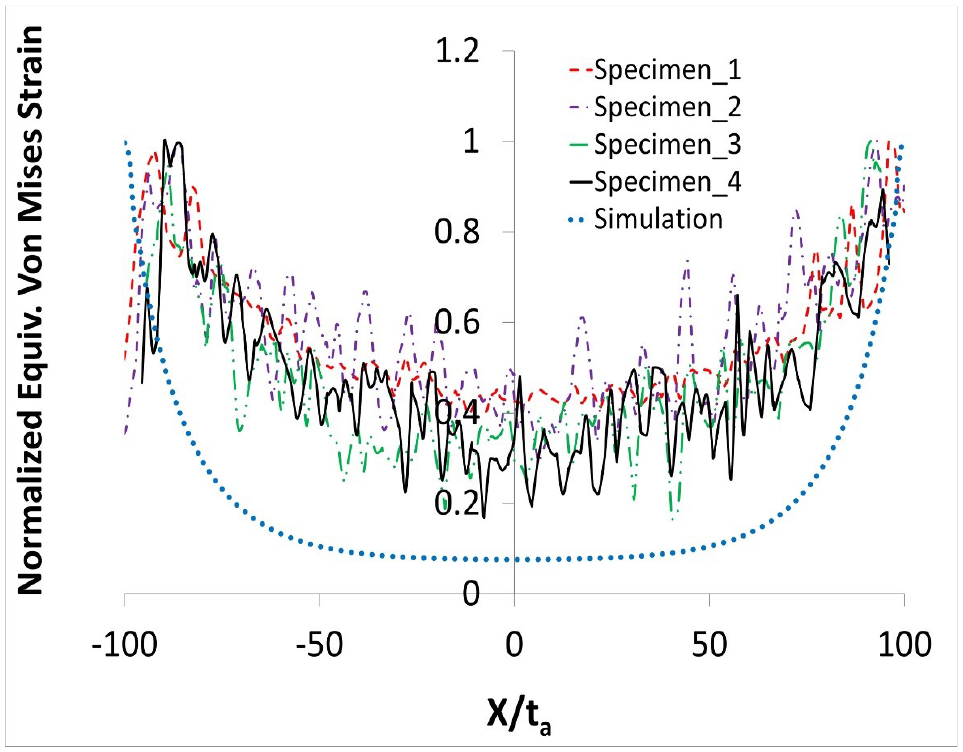
A comparison of equivalent Von Mises strain distributions in the adhesive layer for four experimental results with the result of the numerical simulation.
The experimental strain distribution was obtained from the full strain field captured by DIC (see Figure 4(b)–(c)) from the specimen edge within the overlap region (see Figure 4(a)). While the strain distribution from the numerical simulation is presented in Figure 4(d).
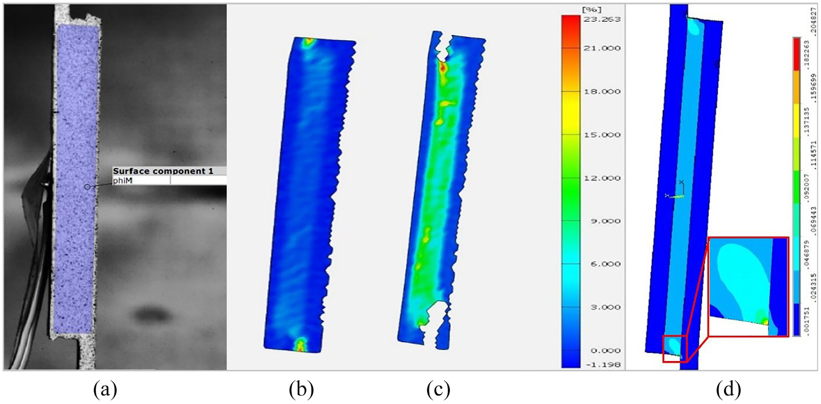
The comparison of strain distributions in the adhesive obtained from tensile test of SLJ (a) by use of DIC (b, c) and FEM (d).
Material properties
The thermo-mechanical properties (Youngs modulus E, shear modulus G, Poissons ratio ν, coefficient of thermal expansion α) of materials are listed in Table 1 (the material notations are given in brackets). 14 Figure 5 shows the stress – strain curves for non-linear aluminum and non-linear adhesive. 14 It should be noted that no time or temperature dependence of the material properties is considered in this study, thus the material properties are assumed to be constant during cooling down and mechanical loading. Similar and dissimilar adherend materials are used to present three different types of SLJ: (1) metal-metal (M-M); (2) composite-composite (C-C) (unidirectional as well as multi-directional laminates); (3) composite-metal (C-M). Four stacking sequences are considered for composite laminates: (a) unidirectional laminate (UD: [08] T or [908] T ); b) quasi-isotropic laminate (QI) with the lay-up [0/45/90/–45] S or [90/45/0/–45] S . The notation presented in Table 2 is used further in the text and graphs.
CFRP, GFRP and Aluminum adherends and adhesive mechanical properties. 14

Indexes: 1-fibers direction, 2-transverse to the fibers direction, 3-out-of-plane direction,
T-tangential (see Figure 5). The material notations used further in the text are given in brackets ().
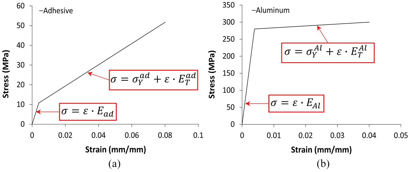
The stress-strain curve for (a) non-linear adhesive material (A N ) and (b) non-linear Aluminum (Al N ). 14
Notations for composite laminates.

Combined thermo-mechanical loading
The current paper only addresses evaluation of residual thermal stresses due to cooling from the manufacturing to the service temperature. Other parameters affecting material properties (e.g. ambient elevated temperature) or stresses (relaxation due to time-dependence of material properties) are not considered. However, the procedure described here for simulation of thermo-mechanical loading is also applicable at elevated (or cryogenic) temperatures if dependence of material properties on temperature is known.
This investigation showed that it is not always possible simply to apply thermal and mechanical loading on the SLJ as a superposition of these loads. The procedure has to be carried out in multiple stages (mimicking the sequence of cooling down of joint after assembly and further mechanical loading). This section describes a method which allows accounting for the residual thermal stresses developed during the cool-down and combining them with mechanical stresses from tensile loading.
The first verification of correctly applied thermo-mechanical loading was done by considering composite laminate (composite plate) only and then the results obtained from ANSYS were compared with Classical Laminate Theory (CLT). In this case thermo-mechanical load was applied on composite laminate and the local stresses in layers as well as global response of the laminate were monitored. The results showed that even using CLT the stress in thermo-mechanical loading depends on the manner of its application. The two scenarios (a) simultaneous application of temperature and strain vs (b) first applying temperature and then strain will give entirely different stress distributions in layers. That is because in case (b) the mechanical load (strain) is applied to thermally shrunk configuration. However, when applying the mechanical load as stress (force) the results coincide within numerical scatter. The same dependence is found from simulation for the complete SLJ: in this case a difference was not only within composite adherend but also with stress distribution in the adhesive layer and global response of the SLJ. In order to investigate the global response for SLJ, the displacement is applied at the free end (at
In order to account for the combination of residual thermal stresses (due to cooling after curing) and mechanical load according to real test sequence to be independent of the loading type (e.g. force vs displacement) or material type (linear elastic vs inelastic), it is more appropriate to split application of thermal and mechanical loads into separate stages. The first stage is to apply temperature on the joint which is not mechanically constrained and is completely free to expand. This stage generates thermal stresses in the components of the joint. These thermal stresses are then applied as initial stresses for the joint subjected to mechanical loading. Use of this procedure was verified on composite laminate by comparing results from ANSYS and CLT.
In case of the composite adherend, the actual procedure of application of thermal and mechanical loads also depends on the way materials have been joined together; (a) two-step assembly: first, composite is manufactured and then parts are bonded to assemble the joint (thermal history may be different); (b) one-step assembly: adhesive and composite adherend are solidified simultaneously at the same temperature. Therefore, two different scenarios for the simulation of the tensile test of SLJ at room temperature are presented: two-stage simulation for metal-metal joint (one-step manufacturing) and two- or three- stage simulation for the joint with at least one composite adherend.
Metal-Metal joint
This case is modeled as a two-stage: (1) application of temperature (to obtain residual thermal stresses developed due to joining at elevated temperature); (2) application of mechanical load. The temperature applied on all of the components of the joint in the first stage is equal to the difference between room temperature 25°C and manufacturing temperature of adhesive 60°C. It should be noted that applied temperature difference (ΔT) is negative (cooling from the manufacturing to the room temperature). Stresses produced during this stage are extracted from ANSYS to generate initial stress state for the joint under mechanical load by reapplying stresses to each node of the FEM model (this is done by using MATLAB code to construct ANSYS input file). Then mechanical load is applied and the second stage of the simulation is carried out.
Composite-Composite or Composite-Metal joints
In case of one-step joining (co-curing) the adhesive layer and the composite adherend are manufactured simultaneously. After thermal stresses are calculated they are applied as initial stresses and mechanical load is applied to complete the simulation.
For this simulation, it is assumed that temperature for manufacturing of the adhesive and composite is the same. The applied temperature is equal to the difference between manufacturing temperature of composite 175°C and room temperature 25°C, thus ΔT = −150°C. The procedure is the same for metal-metal joint, except for temperature difference ΔT = −35°C.
In case the composite laminates are manufactured prior to the bonding and then adhesive joint is assembled, three-stage simulation is performed. Two simulations are carried out to calculate initial stress state in the joint prior to the application of mechanical load. First calculation (due to cooling of composite adherend) generates thermal stresses in layers of the laminate and the second calculation (due to cooling of adhesive) gives the total residual thermal stresses in the adhesive and adherends. The final result is obtained in the third stage when only mechanical load is applied.
The applied temperature in the first calculation is equal to the difference between the manufacturing temperature of the adhesive 60°C and the manufacturing temperature of the composite 175°C, thus ΔT1 = −115°C. The temperature is applied only on the composite laminate and this generates initial stresses in the plies of the composite laminate. The temperature applied in the second calculation is equal to the difference between the room temperature 25°C and the manufacturing temperature of the adhesive 60°C, thus ΔT2 = −35°C. This temperature is applied over the whole joint (note that the initial stress state in the composite is already applied) to generate next stress state prior to application of the mechanical load.
The sequence of application of thermal and mechanical loads is shown in the form of flowchart in Figure 6. The notations 1S and 2S are used for one-step and two-step manufacturing, respectively.

Flowchart for the numerical simulation sequence.
Results and discussion
The analysis here is focused on peel and shear stresses in the adhesive layer of the SLJ with the future goal to analyze the adhesive failure using different strength based criteria. The stress distributions presented in the graphs are along the overlap length from (
Effect of material model (linear vs non-linear) and method of application of thermal load
This section describes the effect of residual thermal stresses developed during the cooling process after curing the composite or the adhesive or both of them on stress distribution within the adhesive layer of SLJ. Cases with linear and non-linear material models (for adhesive and adherends (e.g. aluminum)) are presented. Simulations are performed according to the three schemes described in section “Combined thermo-mechanical loading” (1) T&M, thermal and mechanical loads are applied simultaneously; (2) T+M, thermal and mechanical loads are applied separately and the total stress is obtained as superposition of results from these two calculations (similar approach in other studies12,13); (3) T/M, two-stage simulation with results from the thermal load used as initial conditions for the stage where mechanical load is applied. In order to demonstrate the difference between these three schemes in case of a displacement controlled tensile test, the simulations are done by application of strain
Different schemes to apply thermal load
This section describes the difference between T&M (simultaneous) and T+M (separate, superposition) application of thermal and mechanical loads. Linear adherend and adhesive materials are used within SLJ with similar adherends. The differences between stress distributions obtained from T&M and T+M simulation methods for [Al/A/Al] and [CF1/A/CF1] are shown in Figures 7 and 8, respectively.

The comparison of stress distributions in the adhesive layer of [Al/A/Al] SLJ for T&M and T+M simulation methods,

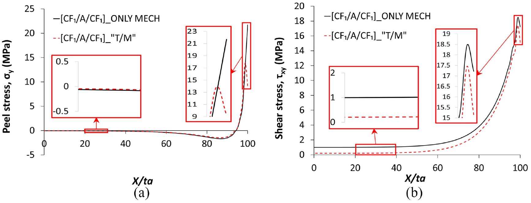
The comparison of stress distributions in the adhesive layer of [CF1/A/CF1] SLJ for T&M and T+M simulation methods,
In case of [Al/A/Al] joint (Figure 7) the differences of stress distributions in the adhesive layer are much more significant than in case of a joint with composite adherends (Figure 8). That is expected because the CF joint has almost zero macroscopic thermal shrinkage and therefore there is no noticeable difference in stresses distribution dependent on the way how to apply the mechanical load (before or after the cool-down). The same agreement is obtained for [GF1/A/GF1] as for [Al/A/Al] with a little bit higher difference in case of [GF1/A/GF1] but stress distributions for this material are not presented here due to limited space. If one looks at global response of the joint, rather than local stress distributions the difference between T&M and T+M cases is also obvious. For example, global force acting on joint calculated at the free end of the joint (at
Effect of material nonlinearity
The comparison between T+M (superposition) and T/M (thermal stresses as initial conditions) is shown in Figures 9 and 10 for aluminum-aluminum SLJ with linear and non-linear material model for adherends and adhesive materials. There is a very small difference between stresses obtained from either of the methods (which is likely due to the numerical error) in case of linear material model is considered (see Figure 9).

The comparison of different stress components in the adhesive layer of [Al/A/Al] SLJ for T+M and T/M simulation methods,

The comparison of different stress components in the adhesive layer of [Al
N
/A
N
/Al
N
] SLJ T+M and T/M simulation methods,
However, if non-linear material model is used the difference between in-plane σx and σz stresses is evident as can be seen in Figure 10, although peel and shear stresses do not differ. The difference between
The comparison between the stress distributions of three cases (only mechanical load vs T+M vs T/M) is presented in Figure 11. The results in Figure 11 show that transition from linear to non-linear behavior occurs at the same location in case of application of mechanical load only or superposition of thermal and mechanical stresses T+M. However, when T/M approach is used (thermal stresses applied as initial conditions) there is obvious difference – the transition point is shifted to the left (similarly to that observed for the increase of the mechanical load 14 ) and it means that the material behavior becomes more non-linear. This supports the statement that simple superposition of stresses in the non-linear region produces results which lack accuracy and the real transition point between the linear and non-linear regions in shear stress distribution cannot be detected. Thus, for more accurate stress calculations and future failure analysis of the joint (as well as for failure of the composite adherend) the T/M method has to be used. According to the previous investigations, the model presented here can handle any type of material at different conditions. To ensure higher accuracy of results the, T/M method is used in the remaining parts of this paper.

The comparison of different stress components in the adhesive layer of [Al
N
/A
N
/Al
N
] SLJ for only mechanical load, T+M and T/M simulation methods,
Effect of residual thermal stresses on the total stress distribution in a joint with linear material model
In this section, only linear material model is considered in order to prevent the interaction between non-linear behavior (transition from linear to non-linear behavior within adhesive material) with other effects (e.g. one or two-step assembly, stacking sequence of the composite laminate, etc.).
Influence of residual thermal stresses on the total stress distribution
In case of C-C and M-M joints two components of the residual thermal stresses inside the adhesive are rather high: in-plane normal stress components

The influence of residual thermal stresses developed after the curing on (a)
Although the overall level of

The comparison of peel (a) and shear (b) stress distributions in the adhesive layer of [Al/A/Al] SLJ with and without residual thermal stresses accounted for, 60 MPa and ΔT = −35°C are applied.
The comparison of peel (a) and shear (b) stress distributions in adhesive layer for [CF1/A/CF1] SLJ with and without residual thermal stresses accounted for, 60 MPa and ΔT = −35°C are applied (with initial conditions on composite ΔT = −115°C).
Influence of processing, one-step versus two-step
This section discusses the results of the simulations performed for similar (CF1 and GF1 adherends) and dissimilar (Al-C joint with one of the adherends being CF1) joint. The results show that one-step assembly may be more favorable than the two-step joining: the reduction of the peel stress concentration at the ends of the overlap and the stress level of shear within the plateau region is more significant in joints assembled by one-step method rather than by the two-step procedure. This positive effect in the one-step procedure is likely a result of the curing temperature in one-step being 175°C, whereas the adhesive curing in the second step of the two-step procedure is at 60°C. This means that increasing the curing temperature results in lower peel and shear stress. This is shown in Figure 15 for C-C joints with similar materials (CF1 and GF1 composite adherends). For dissimilar joints the peel stress in one-step case is reduced at

The comparison of peel and shear stress distributions in adhesive for SLJ with [CF1/A/CF1] (a, b) and [GF1/A/GF1] (c, d) fiber composite adherends for different manufacturing methods of joints (one-step vs two-step method), with and without residual thermal stresses accounted for, 60 MPa and ΔT = −150°C for one-step curing and ΔT = −35°C (with initial conditions on composite ΔT = −115°C) for two-step curing are applied.

The comparison of peel (a) and shear (b) stress distributions in adhesive for SLJ with dissimilar materials [CF1/A/Al] for different manufacturing methods of joints (one-step vs two-step method), with and without residual thermal stresses accounted for, 60 MPa and ΔT = −150°C for one-step curing and ΔT = −35°C (with initial conditions on composite ΔT = −115°C) for two-step curing are applied.
Effect of stacking sequence of the composite laminate
In this section SLJs assembled in one-step with similar materials in adherends are considered. The comparison is made between behavior of UD and QI laminates, as well as between QI laminates with different stacking sequence (fiber orientation in plies adjacent to the adhesive layer is varied: (a) [0/45/90/–45] S ; (b) [90/45/0/–45] S ).
The highest peel and shear stress concentration with longer plateau region (lower stress perturbation zone) are observed for the [908] T composite. The lowest peel stress concentration is obtained for the QI with the lay-up [90/45/0/–45] S (see Figure 17). In the case of the QI laminate, more favorable stress distribution (with lower stress concentration) is obtained when 90-layer is next to the adhesive layer rather than when stiff 0-layer is placed next to the bond line. Swapping 0-layer with 90-layer in the QI laminate results in reduced peel stress concentration at the end of the overlap to ∼30% (see Figure 17) as well as longer plateau region for shear stress is obtained. The thermal effect is apparent when maximum stresses caused by mechanical load 14 are compared with the result of combination of thermal and mechanical loading (see Figure 17 and Table 3). As follows from this comparison, for CF the stress concentration at the end of the overlap is reduced by 40% to 65% (except for CF2 reduction by ∼90%), while for GF the reduction of the stress concentration is by 35% to 50% (except for GF2 reduction by ∼70%). Thus results for the thermo-mechanical loading show that drastically lower peel stress concentration for QI can be achieved simply by swapping 0 and 90 plies within the laminate (this will not change the in-plane stiffness of the laminate, although the bending stiffness will be affected).

The comparison of the stress distributions in the adhesive layer of C-C SLJ with different stacking sequence of plies in adherends, 60 MPa and ΔT = −150°C are applied.
Comparison between the stress concentrations at the end of the overlap for different stacking sequence

Adherend stiffness effect on thermal stresses
In this section the effect of the adherend stiffness on stress distribution in the adhesive with applied thermal load only is demonstrated. In order to evaluate this effect, all the parameters of the joint are fixed and only the stiffness of the adherends is varied. M-M joint (isotropic material) is analyzed with the stiffness values of E = 140, 70 and 35 GPa (ν = 0.33 and shear modulus is calculated).
The results of applying thermal load (ΔT = −35°C) are presented in Figure 18. These data show that four times increase of the adherend stiffness results in the decrease of the peel stress at the ends of the overlap by ∼10%. Similar trend is observed for the shear stresses but with much higher magnitude (comparison is done for relative, not absolute values). Increase of the stiffness of the adherends four times, results in ∼2.5 times decrease of the shear stress at the ends of the overlap. It can be noted from Figure 18 that stresses are rather small, especially the shear stress component. However, the stress values will increase with increase of curing temperature, furthermore these values also depend on the mismatch between thermal expansion coefficients of the joint members. Since the external force is equal to zero, the resulting shear stress should be also zero but locally there is very small shear stress concentration at the ends of the overlap.

The effect of stiffness variation on distributions of peel (a) and shear (b) stress in adhesive for M-M SLJ with linear material model with only thermal load applied ΔT = −35°C.
Summary of the effect of material properties on thermo-mechanical stress distributions
Finally, the analysis showing the effect of thermal stresses on the total stress distribution within the adhesive layer is done by comparing the result from previous work 14 with T/M calculations obtained in this paper, see Figure 19. The results show that the maximum value of the peel stress is reduced with the increase of the bending stiffness of the adherend. But the maximum value of the shear stress is reduced with increase of the axial modulus (Ex) of the adherend. These trends can be described by power function and it is valid for the behavior of GF and CF composites. The T/M results follow the same trend when only mechanical load is present 14 but the level of peel stress is significantly lower.

Maximum peel (a) and shear (b) stress in the adhesive with respect to bending stiffness and axial modulus of adherends for SLJ.
Conclusions
A comprehensive methodology to account for residual thermal stresses developed during the cool-down after curing process of adhesive/composite was worked out by comparing different sequences of application of thermal and mechanical loads. The most common approach used in many publications of simple superposition of thermal and mechanical stresses works well only for linear materials. This approach produces inaccurate results if material is non-linear, since uncoupled thermal and mechanical loads when applied separately may not be high enough to bring material into non-linear region. The model and simulation technique presented in the current paper rectifies this issue and accurate stress distributions are obtained. Analysis of stress distributions in different single-lap joints has led to the following conclusions concerning the stress state in the adhesive layer:
– As expected, high processing temperature causes high in-plane normal stresses inside the adhesive layer for composite-composite as well as for metal-metal joints.
– The residual thermal stresses will reduce the peel stress concentration at the ends of the overlap and the shear stress within the plateau region.
– The one-step assembly (the adhesive and the composite are manufactured simultaneously) for composite-composite joint and composite-metal joint will reduce the peel stress concentration at the ends of overlap more than in two-step joining (the composite is manufactured first and the adhesive is cured when the joint is assembled). The level of the shear stress within the plateau region will be also lower for the one-step curing than for the two-step process.
– In case of a joint with quasi-isotropic composite adherends (CFRP and GFRP) more favorable stress distribution is obtained when the 90-layer rather than the 0-layer is the closest to the adhesive layer. Swapping the 0-layer with the 90-layer will reduce the peel stress at the ends of the overlap by approximately 60% to 70%.
Footnotes
Handling Editor: James Baldwin
Declaration of conflicting interests
The author(s) declared no potential conflicts of interest with respect to the research, authorship, and/or publication of this article.
Funding
The author(s) disclosed receipt of the following financial support for the research, authorship, and/or publication of this article: The research leading to these results was financially supported by Middle Technical University (Baghdad, Iraq), by Polymeric Composite Materials group at Luleå University of Technology (Luleå, Sweden) and by the strategic innovation programme LIGHTer funded by VINNOVA (Sweden).