
Abstract
Numerous ground-based observatories are using small sized ground telescopes for scientific research purposes. The telescopes that are available on the market have three main problems. These issues can be listed as: positioning repeatability, tuning requirement according to different wind speeds for different seasons, and the mass changing via different scientific equipments added to the telescope. This study is aimed at resolving these issues for ground based small alt-azimuth telescopes. Establishing of a set and forget system is performed by designing an adaptive controller. Motor dynamics are taken into consideration for a realistic mathematical model. The Wind-Gust model that consists of a sum of sinusoidal disturbances with unknown phase, amplitude and frequency is used for the wind model. The purposed controller cancels the disturbance effects on the plant while operational positioning and also the makes the plant insensitive to mass changes. The Lyapunov approach is utilised when proving the asymptotic stability. The proposed controller’s success is illustrated with thorough numerical evaluation.
Keywords
Introduction
Space observations will always be important for the goal of space travels and discovering the mysteries of space. In order to observe space, optical telescopes, that can be grouped as ground based and space telescopes, play a vital role.
Thanks to lack of atmosphere and associated atmospheric turbulence that introduces a performance degradation on gathered images (i.e. blurring of images, scintillation, etc), space telescopes provide a better image quality than ground based optical telescopes which are not equipped with Adaptive Optics systems. The fact that the space telescopes are much expensive to build and operate, ground based telescopes are preferred for industry and academia.
Ground telescopes can be divided into three groups; large, moderate and small. Large and moderate telescopes operate with advanced control systems, which are able to sense their surroundings, communicate focal plane instrumentations and operate under observatory control systems. However, small telescopes use traditional control systems due to cost related issues. This paper uses this drawback as an advantage and introduces an adaptive controller in that field.
Academicians work on various different control theories for positioning1–3 and tracking problems 4 of small optical telescopes over the years.
There are various of different techniques are available to control small telescopes;
Taking advantage of this drawback, an adaptive controller is proposed which doesn’t need tuning. Then such system can be called as set and forget. This tecnique is previously studied for optical tracking with an adaptive control on an optical ground telescope. 13 In this paper, Rong Mei, Mou Chen and William W. Guo, cancels the unknown external effect, actuator saturation and parametric uncertainty. The studied telescope system has one degree of freedom and the motor dynamics are not considered in the model. There is another study 14 on this field. It only considers unknown wind disturbance and overcomes this problem by an adaptive controller. This paper contributes and fits the gap available in the literature for telescope controller design in terms of actuator dynamics and unknown plant parameters where also wind disturbance is unknown.
This paper considers alt-azimuth type small telescopes. The purpose of the study is creating a controller for alt-azimuth telescopes which is insensitive to plant parameters, wind disturbance and actuator dynamics. The altitude and azimuth motions are calculated by an adaptive controller which is designed to ensure a precise positioning without need of tuning.
The telescope model, equation of motion and upper controller philosophy are introduced on the second section. The third section introduces the plant assumptions of the system, disturbance parametrisation and backstepping design. The fourth section is giving details about the stability proof of the system. The simulation results are placed on the fifth section. The final section is about the simulation results and real life applications.
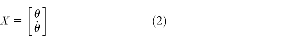
Mathematical model
Mathematical model of the telescope is derived in this section. The model consists of an upper and two lower controllers which is illustrated on Figure 1. The upper controller takes coordinate information about the object of interest which will be observed from astronomers database. The controller has information of the current position and configuration information of the telescope. It generates a reference signal for the lower controller by using inverse kinematics which is computed by comparing the current and desired position and the orientation of the telescope.

Control scheme.
There are two studies in literature about the Telescope Technologies Limited (TTL) 2 m Telescope which formed the basis of mathematical model of this paper. One of the study is about motion control of altitude axis 15 and the other one is about azimuth axis of TTL Telescope. 16 Those two axis are controlled by two different controllers. Principle of the two dynamical models are same, but controller designs are different. This paper merges the two controllers into a single lower controller by using the following principle;


where;

The symbols
Controller design
The design of an adaptive backstepping controller for the telescope model is discussed in this section. The control model scheme is shown on Figure 2. It contains two actuators, which serve to control the angle of the links. The parametric uncertainty of body mass is taken into account. In addition, inertia of the body and actuator terms are considered as unknown.

Control scheme.
The disturbance is not available for measurement. However, all the system states can be measured by sensors. An adaptive backstepping controller is designed by considering available states. Lyapunov approach is used to form the plant for asymptotic stability.
The aim of the proposed controller is to regulate the link motion and pointing repeatability despite the effect of the unmeasured disturbance and mass changing.
Model assumptions
Measurement is available for all states.
Disturbance is unknown.
Disturbance is unavailable for measurement.
The parameters of the system are unknown.
The actuator dynamics is considered.
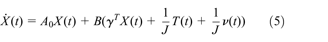
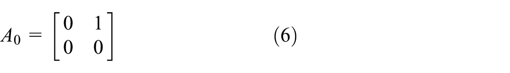
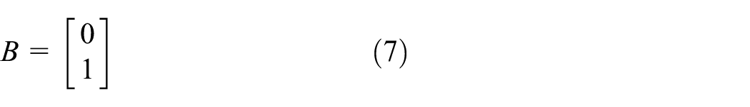
In this section, equation (5) is considered. Where
Since engine torque is not directly applied to the system, it is considered that the torque has following dynamics


where the parameters (
Wind disturbance representation
The wind disturbance is modelled as an output of an exosystem;


The
It is assumed that

It can be said that 13 is invertible. So, the exosystem is written in the following form by using the coordinate transformation


The filters of the equation;


and the estimation error obeys the equation;

Proof. The estimation error is defined below;

By differentiating
Also, by substituting (17) into (5), then the system can be written as;
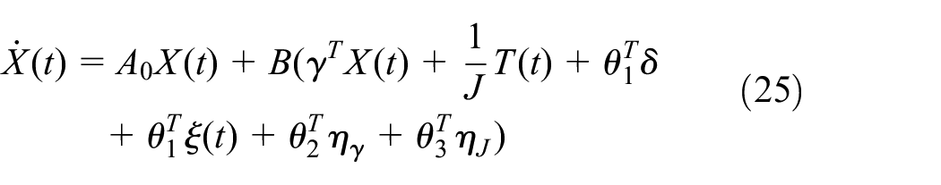
where
Backstepping design
In order to track the reference, the following error system is defined as;

where;

The desired controller can be defined as;

In addition, the second error is defined for motor torque. The error is given by

Taking the time derivative of
where
The actual input can be chosen as

where


Stability Proof
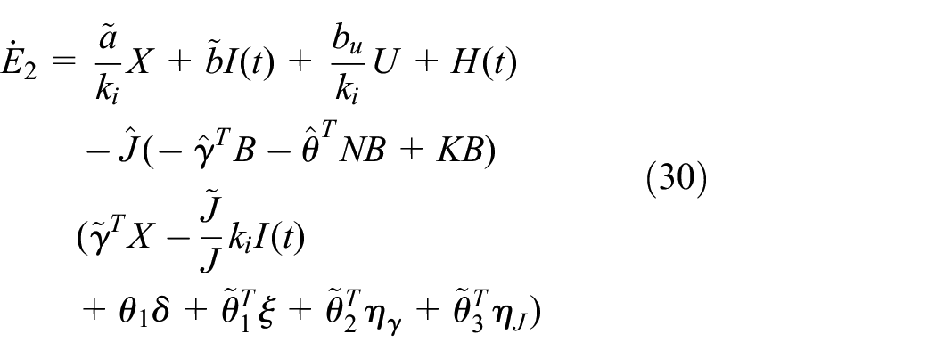
Proof. To accomplish the Lyapunov Function, the closed loop system is re-written by substituting (26) into (25) and (32) into (30).


Then, Lyapunov function is defined as follows;

Taking time derivative of the Lyapunov Function;

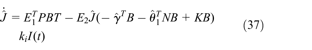
Substituting the update laws into the (44) and applying Young’s Inequality for cross terms, we get;

where
Then it can be concluded that
Simulation results
In this paper, a global adaptive controller is designed. It is claimed that the proposed controller has better performance outputs than a conventional PID controller, it doesn’t need tuning for summer and winter seasons because of the environmental effects and it also doesn’t need tuning when mass of the plant is changed. In this section those claims will be proven.
To demonstrate the performance of the controller, the sinusoidal wind disturbance in Figure 3 is applied to the plant. The applied disturbance is based on Wind-Gust model. Then, it can be said that the applied disturbance is close to reality.


Wind speed.
The Figure 4 aims to show a visual comparison of PID and adaptive controllers behaviour which are applied to the plant. When an astronomer wants to observe a star, the telescope link angles aren’t fixed during the operation, because of the relative motion of both earth and stars. This simulation includes fixed references, it means the telescope doesn’t lock on a star and not executing following up operation. In other words, this simulation is reflecting an area observation. As it is aimed, the applied adaptive controller converges to the reference coordinates better than PID and also conserves better its position under wind disturbance (46).

End effector angle.
The Figure 5 describes the level of success about trajectory following ability of the PID controller and adaptive controller. The purposed adaptive controller is considerably more successful if the PID controller isn’t tuned for changing conditions.

RMS comparison of the controllers.
The Figure 6 indicates different masses applied to the controller under disturbance (46). The adaptive controller is designed to handle mass changes without tuning. Astronomers can make observations by using a CCD camera or occular. Those two apparatus cause changing mass properties of the system, and creates different moments on the joints. Thereby, the PID controller can’t handle this changes, and fails to place focal point of the telescope on the target point. Generally a CCD camera is about 6 kg, and its filters which have variety of masses are changing according to observation type. This simulation shows that telescope is executing following up operation which means it is locked on a planet and moves according to the relative motion between earth and the planet. When mass is increased, system converges to the reference later. However, controller handles mass changes and after its learning period of the plant, it follows the reference successfully. As a result, this controller is applicable for aforementioned configuration telescopes, independently of their size and mass differences.
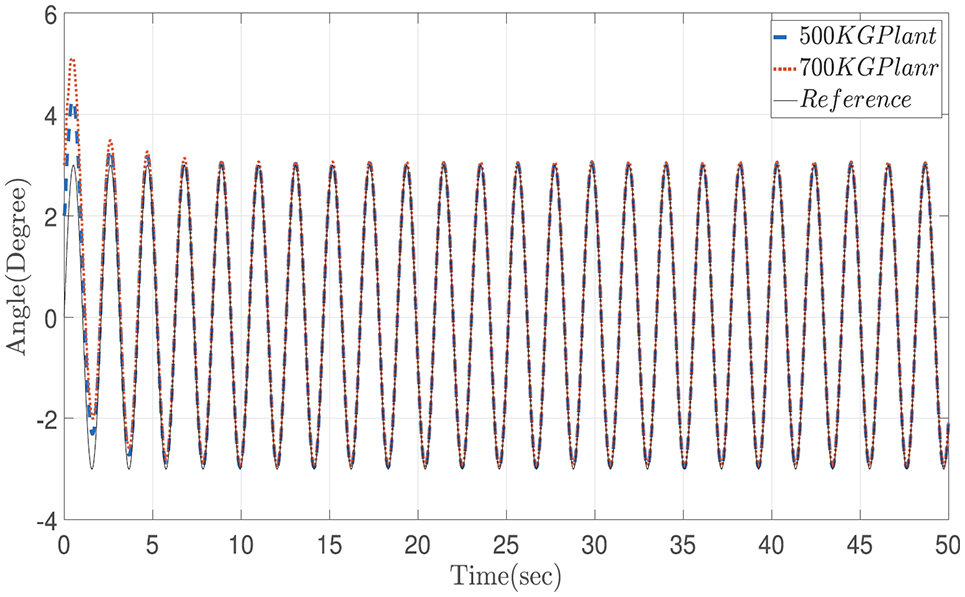
End effector angle.
The Figure 7 shows the motor input of the 500 kg system in the Figure 6. The first 5 s oscillation is seen due to the learning period of the adaptive controller.

Angle of the end effector.
Conclusion
This study introduces an adaptive backstepping controller for ground based small alt-azimuth telescopes. The aim of the paper to create a controller for all mentioned type and class of telescopes. In the presented approach, the motor parameters and plant dimensions are considered as unknown. The controller is also designed for operating under unknown wind disturbance which provides geographical location freedom for the deployment of the telescope. Additionally, the controller is insensitive for mass changes. This ability enables astronomers to change detectors and associated filters during operations or modify their system setup without the need of tuning, that results on loss of observation time.
There are a few assumptions are made; all parameters are unknown and all states are available for measurement except the wind disturbance signal. An observer is designed to defeat the unmeasured signal problem. The wind disturbance is assumed as a sinusoidal wave where the phase, amplitude, and frequency contributions are unknown. Then, the adaptive backstepping controller is designed to generate the motor torques which is proportional to the current. Lastly, the Lyapunov Candidate Function is used to demonstrate the stability of the plant.
The success of the controller is demonstrated by simulations. The results show that the proposed controller converges to the reference signal much faster than the PID controller. In addition, it is shown that the designed adaptive controller is not effected by mass and moment changes. This proves that it can be used as a universal controller for the 2-DOF configuration telescopes.
Footnotes
Acknowledgements
The authors would like to thank the technical guidance and funding support of Isik University, Center for Optomechatronics Research and Application (OPAM),and Ataturk University Center for Astrophysical Application and Research (ATASAM).
Handling Editor: James Baldwin
Declaration of conflicting interests
The author(s) declared no potential conflicts of interest with respect to the research, authorship, and/or publication of this article.
Funding
The author(s) received no financial support for the research, authorship, and/or publication of this article.