
Abstract
The aim of this present study is to analyze numerically the buckling behavior of cracked thin bi-material structures subjected to compression and tensile stresses and this, by considering the evolution of crack lengths and its orientations at the interface. This research work allows to quantify numerically the buckling phenomenon which can affects the thin plates for both cases, with and without interface crack especially, when the plate is subjected to tensile loading. The main important results of numerical simulations show that for the case of compression loading, the presence of interfacial crack increases significantly the strength of the thin plate against buckling phenomena. In the other hand, thin crack plates buckling is more pronounced when the crack tip is close to the interface (θ = 90°, θ = 75°). Finally, unlike to the case of homogeneous thin plates, the incorporation of bi-material aspect in thin plates design offers more strength against buckling either for compression or tensile loading.
Introduction
The use of thin structures, plates, and shells, particularly those composed of at least two different materials, is now widely used in various fields. Thin plates are easily subject to shape instability, mainly buckling due to compression, particularly when the thickness of the plate is low. In addition, buckling resistance is an essential parameter in the evaluation of the load capacity of these plates. The buckling phenomenon can also take place under the action of tensile stress when there are cracks or holes in the plates. Thin plates are generally exposed to damage (cracks, corrosion, chemical attack, etc.), and this can impair their structural integrity and may certainly affect their service life by reducing their buckling resistance. Furthermore, the presence of cracks in such structures can considerably affect their load capacity. R Brighenti1–3 worked on thin-walled structures; he mainly investigated the buckling of cracked rectangular thin plates. Recently, several numerical and experimental studies were carried out using the finite element method to analyze buckling strength for cracked panels under different load cases.4,5 The critical load multiplier may be determined by varying certain parameters, such as the length of the crack, the Poisson’s ratio, and the orientation of the crack. AV Raviprakash et al. 6 worked on the critical buckling load for a thin square plate with center or edge cracks, and subjected to axial compression. The numerical study was carried out by the finite element method. These authors studied the static buckling load for different lengths and orientations of a crack. YV Satish Kumar et al. 7 studied the buckling loads of cracked plates. The hierarchical trigonometric functions were used to define the displacement function of the cracked plate. X Wang et al. 8 analyzed the buckling of rectangular thin plates, with nonlinear charges distributed along the two opposite ends of the plate, using the differential quadrature (DQ) method. E Riks et al. 9 used the finite element method to analyze the post-buckling behavior of cracked plates subjected to tensile stress. R Seifi and Khoda-Yari 10 conducted an experimental and numerical study on the buckling of thin, cracked plates subjected to total and partial axial compression applied to the edge of the plate. To this end, rectangular plates, made of 1200 Aluminum alloy with a central inclined crack, were used. It is generally believed that it is difficult to bend thin plates under tensile stress. However, when they have a hole, compression stresses occur locally near that hole. These compression stresses can cause local buckling which is called plate buckling under tensile stress. S Shimizu 11 carried out a numerical analysis on the buckling behavior of plates containing a hole under tensile stress. The authors in literature12,13 have investigated the buckling behavior of simply supported plates reinforced by stiffeners, with variable spacing. The analysis assumes that the state of stress in the plate before, during, and after buckling is in the elastic domain. MR Khedmati et al. 14 studied the effects of length, position, and orientation of the crack on the buckling load multiplier.
The aim of the present work is to investigate numerically the buckling instability of homogeneous and bi-material virgin and cracked thin plates similar as the ones analyzed by NK Tani et al. 15 and T Tamine et al. 16 The cracked panels are subjected to compression and tensile stress, in order to evaluate the influence of the presence of a crack and its inclination on the behavior of the plate during buckling phenomena.
Description of the problem
Thin rectangular plates are considered and characterized by their dimensions: length (2L), width (2W), and thickness (t), as shown in Figure 1. These plates are made of a homogeneous or heterogeneous material, cracked and subjected to compression and tensile stress. The cracks are inclined by an angle α = π/2 −θ with respect to the interface (θ is the angle of inclination of the crack with respect to the loading direction).

Thin plate with inclined crack, subjected to compressive stress σ0: (a) homogeneous plate; (b) bi-material plate.
The materials chosen for this study are Aluminum alloy and Steel, commonly used in the study of bi-materials. The mechanical properties of these materials are given in Table 1.
Mechanical properties of the materials.

Modeling and numerical simulation applied to the study of buckling instability of cracked homogeneous plates
Buckling of a homogeneous and virgin thin plate subjected to compression and tensile stress
This first stage of the study on the behavior of thin plates, with buckling instability, consists of comparing the numerical results obtained by the calculation code with the ANSYS® finite elements with those calculated analytically. For this purpose, a simple, virgin, flawless plate was subjected to compression and tensile stress, with buckling instability. For uncracked virgin plates, subjected to compression and tensile strength, the reference solution for the critical buckling load multiplier is given in Brighenti. 1
The relations giving the critical buckling load multipliers are expressed by Brighenti 2 in the form
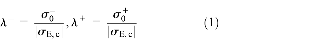
For the case of rectangular uncracked plate, as presented in Figure 2 above, the critical buckling stress

where D represents the plate stiffness, calculated by the following relationship


(a) FE meshing of homogeneous virgin plate by ANSYS® Software. 18 (b) Shell93 finite element for plate buckling analysis.
The finite element modeling of the plate is performed using a regular quadrilateral discretization with Shell93 isotropic elements (Figure 2) which are assumed suitable for the thin plate structures meshing into 1800 Shell93 elements. These adopted finite elements are defined by eight nodes, four thicknesses, with six degrees of freedom at each node: translations in the nodal x, y, and z directions and rotations about the nodal x, y, and z axes. 19
For the whole studied cases, the total number of Shell93 elements is maintained and the mesh pattern of the central part of the plate around the cracked zone is kept identical; except slight elements arrangement outside of this flawed zone is carried out, in order to have the appropriate values of the dimensionless geometrical parameter ratios. The plate is subjected to a uniform compressive external stress, σ0 = −1.0 daN/mm2 (Figure 1) distributed along the both plate opposite width edges (2W). The boundary conditions concern the four plate edges, which are considered, simply supported in out-of-plane direction. Hence, the buckling coefficient k (equation (2)) is adopted equal to 4.0. 17
The results, in terms of buckling load multipliers, obtained by the analytical method and the finite element method are summarized in Table 2 bellow for different plate buckling modes.
Comparison of the results of buckling load multipliers under compression.
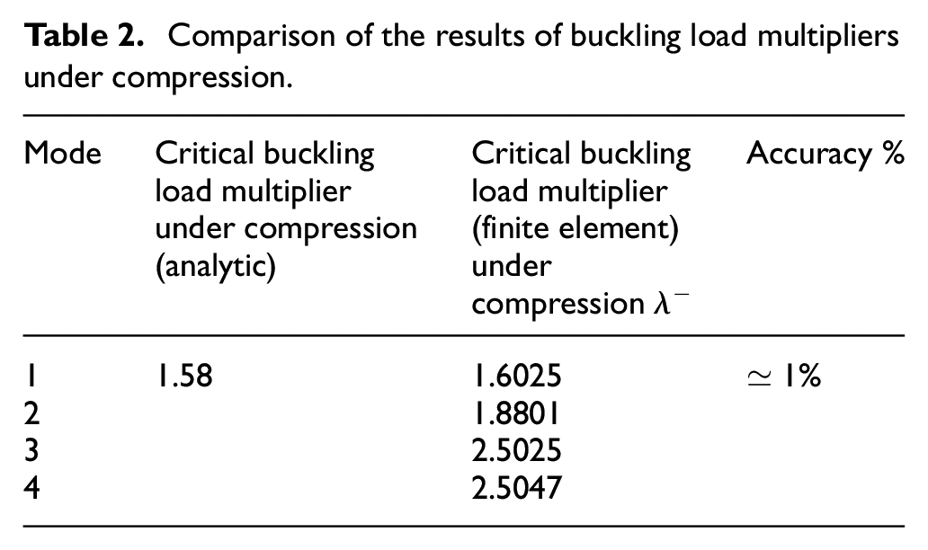
The values of buckling load multipliers λ−, shown in Table 2, are obtained numerically based on eigenvectors and eigenvalues analysis, which implicates in equilibrium equation conditions of finite elements model. The ANSYS® software solves the eigenvalue problem, by means of the Lanczos numerical method. 18 Therefore, the lowest obtained eigenvalue, λ−, represents the critical buckling load multiplier when the elastic buckling occurs.
The results obtained by the finite element method are found to be consistent with those computed by the analytical method (equation (2)). The dispersion is of the order of ≃1% for mode 1 of the buckling of a thin virgin plate subjected to compression. Figure 3 represents the buckling modes of a virgin (uncracked) plate that is subjected to compression with its buckling eigenmodes obtained by the finite elements analysis.
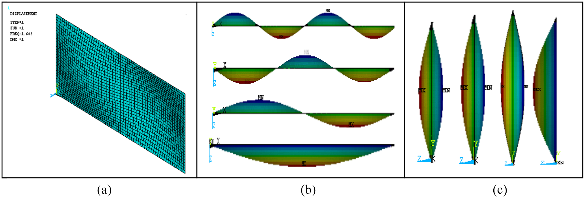
(a) Buckling of a thin virgin plate under compression. (b) and (c) Buckling modes of a thin virgin plate subjected to compression.
Buckling of homogeneous thin plates with inclined central cracks
Buckling of a cracked thin plate subjected to compression
In this section, the homogeneous thin plate buckling was analyzed numerically using the finite element method in order to determine the buckling load multipliers in mode 1. The cracked thin plates of 2W = 400-mm width, 2L = 800-mm length, and t = 1-mm thickness are subjected to compression loading, and for which, the effect of crack inclination angles θ° on plate buckling is analyzed. The values of the critical buckling load multiplier under compression are plotted as a function of the ratio (a/W) (crack length over plate width) and the inclination angle θ (Figures 4 and 5).

Evolution of the critical buckling load multiplier λ− of homogeneous cracked thin plates under compression.

Evolution of the critical buckling load multiplier λ− of a homogeneous cracked thin plate under compression as a function of the inclination angle θ°.
The curves, representing the values of the critical buckling load multipliers λ− under compression, are decreasing functions for the different inclination angles, except for θ = 0°. This decrease is also reported in the works of Brighenti 2 in the case of buckling of a cracked plate subjected to compression and tensile stress, but with boundary conditions different from ours.
The results obtained by the finite element method show that the values of the critical buckling load multiplier λ− are inversely proportional to the relative crack length a*. Thus, the presence of cracks greatly reduces the resistance to buckling of the homogeneous thin plate, except for the case of the inclination angle θ = 0°, where it is easy to note that λ− is proportional to a, which makes the plate more resistant. This is called the crack closure phenomenon. It can also be seen that the compression buckling load multipliers λ− decrease with the increase in the inclination angles θ of the crack until it reaches the value θ = 90°, which is considered as the critical buckling angle under compression.
Buckling of the homogeneous cracked thin plate subjected to tensile stress
The results obtained for the critical buckling load multipliers for the plate under tensile stress are plotted as a function of the ratio a/W (Figure 6) and as a function of the inclination angle θ (Figure 7).
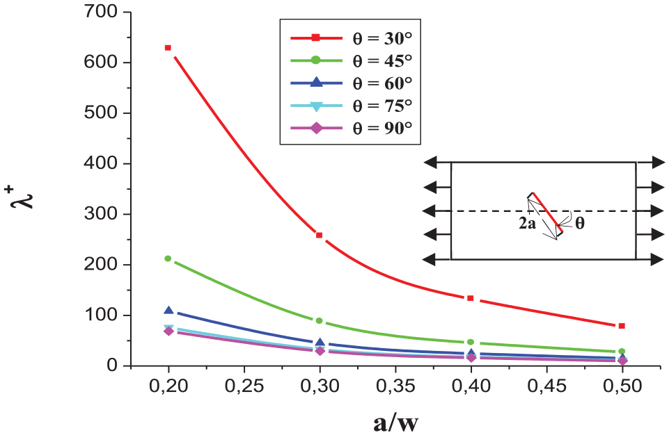
Evolution of the critical buckling load multiplier under tensile stress λ+ of a cracked thin plate.

Evolution of the critical buckling load multipliers under tensile stress λ+of the cracked thin plate.
The study of buckling under tensile stress showed that the lower the inclination angle (30°) the greater the critical load. This can may be due to the weak diminution of plate rigidity in comparison with case of the other inclination angles (45°, 60°, 75°, and 90°) where plate rigidity become, respectively, too weak and buckling resistance decreases significantly (Figure 8).
Buckling of cracked thin plates in mode 1 under compression (b), (d), (e), (f), (h), (j), (l), (n), and under tensile stress (a = 0.5, θ = 0°, 15°, 30°, 45°, 60°, 75°, 90°).
In the other hand, plate buckling resistance evolution becomes stationary whatever the crack length, this can be clearly observed since the crack inclination angle exceeds 60° (see Figure 6).
Modeling and numerical simulation applied to the study of buckling instability of cracked bi-material plates
Buckling of a cracked bi-material virgin thin plate subjected to compression and tensile stress
In order to determine the critical buckling load multipliers, an analysis was carried out on a thin bi-material plate subjected to compression and tensile stress. The meshing of the homogeneous plate in Shell93 elements is given in Figure 9.

Shell93 finite element meshing of a thin bi-material plate.
The critical buckling stress of bi-material plate is computed based on the minimal values of Young modulus, E = 69,000 MPa and this based on the following hypothesis which states that the buckling instability phenomenon of bi-material thin plates can probably occur at the compressive stress concentration zones in the side of the weakest mechanical properties medium which is in our case the Aluminum alloy materials. The results of the buckling load multipliers obtained by the finite element method are shown in Table 3.
Comparison of critical buckling load multipliers of the thin plate subjected to compression stress.

Buckling load multipliers under tensile stress are significantly larger than those under compression. This means that it is easier to bend a bi-material thin plate subjected to compression than to tensile stress.
Buckling of a thin bi-material plate with an interface crack, subjected to compression and tensile stress
In this section, the buckling of a thin bi-material plate with an interface crack was analyzed numerically using the finite element method. Figures 10 and 11 show the critical buckling load multipliers of a homogeneous thin plate with a central crack for the inclination angles θ = 0°, 15°, 30°, 45°, 60°, 75°, and 90°, under compression.

Variation of the critical buckling load multipliers λ− of cracked thin bi-material plates subjected to compression as a function of the inclination angle θ°.

Evolution of the critical buckling load multiplier for a thin bi-material plate as a function of the crack length and inclination angle θ.
When the crack tips are close to the interface (θ = 90°, θ = 75°), the critical stress decreases with increasing crack length. For angles equal to 30° and 45°, the critical stress increases slightly with the ratio a/w, which means that it is easier to bend a cracked plate under compression when the crack is close to the interface.
Also, Figure 10 above shows that critical buckling load multipliers λ− change slightly between −1.803 and −1.797 for the case where the crack growths in different mediums of the bi-material plate. These variations for theta 0° of the crack are due to the finite element meshing discontinuities between crack upper and lower lips which increase with relative crack length a/W.
Unlike the case of the uncracked bi-material plates, as much as the number of separated finite element nodes of crack lips increases when the crack growth, the material dislocations, and meshing discontinuities affect significantly the values of critical buckling load multipliers λ− for this particular case of cracked bi-material plate configuration (θ = 0°).
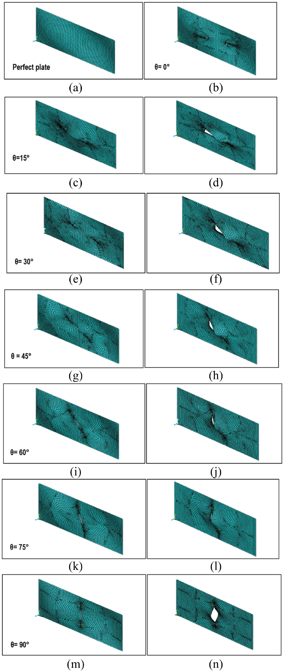
Figure 12 shows the critical buckling load multipliers of a homogeneous thin plate with a central crack for inclination angles θ = 0°, 15°, 30°, 45°, 60°, 75°, and 90°, under tensile stress. For the same crack inclination angle (θ≠ 0), the critical buckling load decreases as the crack length increases. These variations can be explained by the reduction of plate stiffness with the evolution of relative crack length which directly affects the bi-material buckling strength. It is also very important to notice that the variations of critical buckling load multiplier become insignificant when a/W is over the 0.3 and converge near λ+ = 0. Figure 12 below displays a bi-material cracked thin plates with different inclination angles θ, for the first buckling mode and for a crack length ratio a* = 0.5.

First buckling mode of thin bi-material plates cracked at the interface, under compression (b), (d), (e), (f), (h), (j), (l), (n), under tensile stress (a* = 0.5,
Figures 12 represent the values of the critical buckling load multiplier of a homogeneous thin bi-material plate with a central crack for inclination angles θ, under compression and tensile stress. The obtained numerical results show that inclination angles θ and relative crack lengths a/W have a significant effect on the buckling strength of bi-material plates. For the case where the bi-material specimen is subjected to tensile loading, the buckling phenomenon appears slightly and the specimen resistance decreases and becomes stationary when the relative crack length exceeds (a/W = 0.2). At the stage, the inclination angles effects are not highly significant. In comparison with the case of homogeneous cracked plates analyzed in section 3 “Modeling and numerical simulation applied to the study of buckling instability of cracked homogeneous plates” above, where the stiffness is uniformly distributed all over plate surface, the buckling strength of bi-material cracked plate decreases due to the variations bi-material plate stiffness from the interface.
Conclusion
The curves, representing the values of the critical buckling load multipliers λ− under compression, are decreasing functions for the different inclination angles, except for θ = 0°. This decrease is also reported by other authors, in the case of a homogeneous cracked plate subjected to compression, for various boundary conditions.
The values of the critical buckling load multiplier λ− under compression are inversely proportional to the relative crack length a*. Thus, the presence of cracks greatly increases the resistance to buckling of the homogeneous thin plate.
The buckling load multipliers under tensile stress are significantly larger than those obtained under compression. This means that it is easier to bend a thin bi-material plate under compression than under tensile stress.
Under compression, when the crack tip is close to the interface (θ = 90°, θ = 75°), the critical stress decreases as the length of the crack increases. This means that it is easier to bend a cracked plate under compression when the crack is close to the interface.
Cracked thin bi-material plates are more resistant to buckling, under compression and under tensile stress, than homogeneous thin plates.
Footnotes
Handling Editor: James Baldwin
Declaration of conflicting interests
The author(s) declared no potential conflicts of interest with respect to the research, authorship, and/or publication of this article.
Funding
The author(s) disclosed receipt of the following financial support for the research, authorship, and/or publication of this article: The authors gratefully acknowledge the support of the Directorate General for Scientific Research and Technological Development (DRSDT) and the Algerian Ministry of Scientific Research.