
Abstract
Uneven load sharing of a planetary gear set is the main cause of preventing the miniaturization and weight reduction of a planetary gearbox. Non-torque loads and carrier pinhole position errors are the main factors that worsen the load-sharing characteristics. However, their effects are seldom analyzed at a system level especially for an off-road vehicle. To make up this gap, some simulation models are proposed to investigate the effects of floating members on the load-sharing characteristics and the strength of a planetary gear set with non-torque load and carrier pinhole position error. When the error is not considered, the mesh load factor converges to unity irrespective of the type and number of floating members and the safety factors for pitting and bending are increased slightly. When the carrier pinhole position error is considered, the mesh load factor dramatically worsens. Although it is improved using the floating members, it does not converge to unity. However, the bending safety factor of the planet gear with the error is increased by 26%. This indicates that the design modification for the original planetary gearbox is needed to satisfy the safety factor requirement, but the problem is solved using only floating members.
Keywords
Introduction
Recently, owing to the increasing importance of fuel efficiency, attempts have been made toward the miniaturization and weight reduction of the traveling gearboxes of eco-friendly vehicles such as electric automobiles and forklifts. A planetary gear set (PGS) has high power density in comparison to a spur or helical gear set, and therefore, it is commonly used in the reduction gearboxes of traveling devices. To reduce the size and weight, and increase the life of a PGS, uniform load sharing should be achieved. 1 In an ideal condition, the power transmitted to a PGS is uniformly distributed to each planet gear. In practice, however, it is well-known that uneven load sharing occurs owing to non-torque loads and various manufacturing and assembly errors.1–7
Because uneven load sharing, due to manufacturing and assembly errors, reduces the life of planet gears, many studies have attempted to solve this problem. Kahraman 4 developed a mathematical model of a PGS to analyze the dynamic load-sharing characteristics. This study found that pinion run-out errors and tangential carrier pinhole position errors had the greatest effect on the dynamic characteristics and the former error can be minimized through in-phase arrays. Oh and Cheon 8 analyzed the effects of manufacturing and assembly errors on the static characteristics of a PGS using the finite element method (FEM). They found that errors related to the planet gear had the largest effect and the load-sharing characteristics of the PGS were the most affected by the tangential errors of the planet gear. Bodas and Kahraman 2 analyzed the load-sharing characteristics of three to six planet gears with various manufacturing and assembly errors. They found that uniform load sharing occurred despite the manufacturing and assembly errors in three planet gears. However, in four or more planet gears, load sharing was significantly affected by the tangential error of the planet gear and could not be improved by increasing the number of planet gears. Ligata et al. 5 experimentally studied the effects of the number of planet gears, torque level, and carrier pinhole position errors on load sharing and gear root stress. Their results were consistent with those predicted using mathematical models in previous studies. Iglesias et al. 9 investigated the effects of planet position errors on load sharing and transmission error in two different configurations of PGS. It was confirmed that the tangential error affects more greatly the load sharing than the radial error. The errors also increased the static loaded transmission error. Recently, Leque and Kahraman 10 enhanced the mathematical models for planet load sharing through a three-dimensional (3D) formulation of PGS, including all the three types of manufacturing errors. The relative positioning of errors with respect to each other was critical to defining the resultant planet load sharing. Li et al. 11 analyzed the load sharing of compound PGS with cracked sun gear. A nonlinear lumped-parameter model of the PGS was established and the impact of crack propagation on the load-sharing behaviors was revealed. Although many previous studies have analytically or experimentally investigated the load-sharing characteristics of a PGS, they focused on a simple PGS and the effect of carrier pinhole position errors on load sharing at a system level remains unclear.
With the carrier pinhole position errors, a non-torque load is recently considered as one of the main causes for the uneven load sharing.6,12,13 The non-torque load is defined as a load component with five degrees of freedom due to the self-weight or irregular workload, but not torque, of the mechanical system. Many studies have investigated the effects of non-torque loads on the load-sharing characteristics of a PGS.6,11,14–17 These works have used analytical and experimental methods to investigate the load-sharing characteristics of a PGS when both torque and non-torque loads are applied to a gearbox for wind turbines. However, little work has been conducted about the load-sharing characteristics of a reduction gearbox for off-road vehicles such as forklifts and farm tractors, because they are generally engine-driven and weight reduction of the gearbox is not important. As some off-road vehicles use electric motor as power source, the miniaturization of a gearbox becomes invaluable. In off-road vehicles, large vehicle weight and workload produce non-torque loads on the wheels. Because most of them use a PGS in the final reduction gearbox and a carrier is connected to a wheel adapter, non-torque loads cause the carrier deflection and uneven load sharing occurs. Therefore, when analyzing the load-sharing characteristics of the PGS in the traveling reduction gearbox used for an off-road vehicle, both the non-torque load and carrier pinhole position error must be considered.
The use of a flexible or floating member is recommended to improve the uneven load sharing of a PGS. The former makes load sharing uniform using a planet pin or a ring gear made of a flexible material.18–20 The latter makes one or more members of the PGS freely movable in the radial direction from the nominal position without being constrained by bearings. 16 Zhu et al. (2013) proposed the model representing the coupled lateral-torsional dynamic response of PGS with double cantilevered flexible pin. They showed that load sharing of PGS depends heavily on the magnitude of the error, supporting stiffness, and input torque. Xu et al. 20 also developed the dynamic model of PGS where gear contact loss nonlinearity and bearing clearance nonlinearity were integrated. The nonlinear effects could be reduced by lower flexible pin stiffness and gear contact loss occurs in a strong vibration position to reduce system stiffness. Kahraman and Vijayakar 21 noted that the load-sharing characteristics of a PGS were significantly improved when using floating members instead of when flexible members were used. Therefore, floating members are generally used to improve the load-sharing characteristics of a PGS.3,7
This study analytically investigated the effect of a floating member on the load-sharing characteristics of a PGS with a non-torque load and carrier pinhole position error. Although several previous studies have investigated the effects of each factor on the load-sharing characteristics of a PGS, few have verified the effect of floating members on a PGS when both factors are considered. Furthermore, the improvement on the load distribution and the strength by the floating effect has rarely been reported. It is notable that floating members improve the load-sharing characteristics, the variance of contact stress, and the gear strength of a PGS whether it is subjected to only a non-torque load or both a non-torque load and carrier pinhole position error. In addition, it is confirmed that there are limitations in improving the load-sharing characteristics with floating members at the gearbox system level.
Materials and methods
Gearbox system description
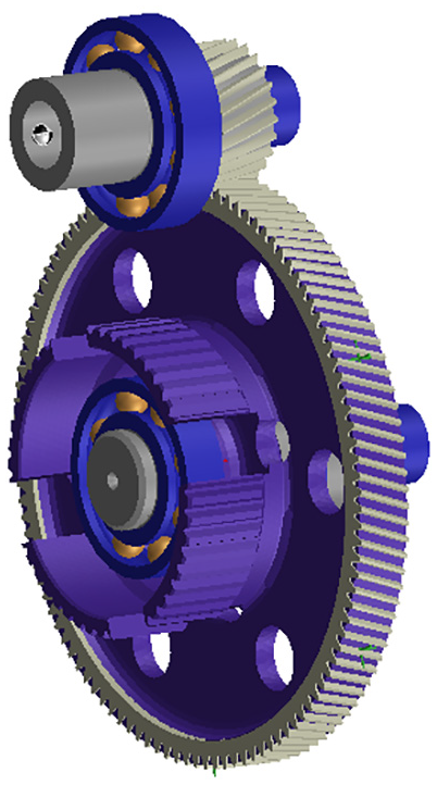
The object in this study is a planetary gearbox used in an electric forklift as a reduction gearbox. The use of PGS inevitably introduces carrier pinhole position errors, which is a type of manufacturing and assembly error. In addition, owing to the operating conditions of an electric forklift, a large ground reaction force due to the weight and workload acts on the gearbox connected to the wheels. As shown in Figure 1, the gearbox consisted of a parallel shaft gear set and a PGS with four planet gears. The sun and ring gears were mounted on the sun shaft and the housing, respectively. Each shaft and the carrier were supported at both ends by two bearings. A motor connected to the parallel shaft gear set supplied power to the PGS’ carrier. A ground reaction force, which was a non-torque load, was applied to the carrier of the PGS connected to the wheel. The power input condition of the gearbox was 150 Nm at 1000 rpm and the non-torque load was 62 kN in the vertical direction. The parameters of the PGS are described in Table 1.

Structure of the gearbox.
Parameters of the PGS.

PGS: planetary gear set.
Gearbox simulation model
The gearbox simulation model used in this study was developed using commercial software. Because the gears and bearings have nonlinear stiffness, the stiffness accuracy must be increased to obtain meaningful analysis results from gearbox simulation models.17,22 The simulation model used in this study defined the gear stiffness by considering the macro- and micro-geometry of the gear. When defining the bearing stiffness, the shape of the components, such as the diameter of the ball and curvatures of the inner and outer rings, as well as the factors that affected the nonlinearity of the rigidity, such as the internal clearance and contact between each ring and the ball, were considered.
Figure 2 shows the gearbox simulation model used in this study. The analysis of gearboxes considering non-torque loads requires accurate calculations of the deflection of the components. Therefore, it is important to define the stiffness of gears, bearings, and other components such as the housing, shafts, and the carrier. However, these components have very complicated shapes, as shown in Figures 2–4, respectively. In this study, to ensure accuracy, their stiffness was defined using finite element (FE) models.

Gearbox simulation model with FE housing (left) and without FE housing (right).
Parallel gear set with FE web.

Planetary gear set with FE carrier (left: isometric view and right: side view).
Eight simulation models were developed to analyze the effects of floating members on the load-sharing characteristics of a PGS when a non-torque load and a carrier pinhole position error were considered. Table 2 lists the analysis conditions for each simulation model. Models 1–4 were developed to verify the effects of the floating members when only a non-torque load was considered. Models 5–8 were developed to verify the effects of the floating members when the non-torque load and carrier pinhole position error were considered. A sun and ring gears were selected as floating members to investigate their effects on the gearbox structure. To make the sun gear float, a radial clearance was applied between the gear and its shaft. Figure 5 shows the radial clearance in simulation model. The simulation method to float the ring gear in this model was used in the previous study 23 where one can find more details.
Analysis conditions for simulation models.

C: considered; NC: not considered.

Radial clearance between sun gear and shaft for floating.
Singh 7 reported the occurrence of the same effect despite the type of floating member. Furthermore, he reported that floating members resulted in limited improvements on the load-sharing characteristics of a PGS. This was because he modeled the analytical PGS by allowing the carrier assembly to float with respect to the sun and ring gear centers. In his floating behavior model, it was the relative motion of the individual members that was important. However, the model had drawbacks, in that any non-torque load was not considered and the analysis was not conducted at the gearbox system level. To overcome these problems, this study proposed the gearbox simulation model with considering a non-torque load and investigated it at a system level.
Carrier pinhole position errors
Carrier pinhole position errors deteriorate the load sharing of a PGS because a gear mesh occurs first or later in planet gears with such errors. For a PGS with four planet gears, carrier pinhole position errors were applied and similar loads were distributed to planet gears that were placed diagonally. When the load-sharing characteristics of the PGS deteriorated significantly, carrier pinhole position errors of the same or different phase were applied to the diagonally placed carrier pinholes or two consecutive carrier pinholes.1,4 The same results were obtained when the carrier pinhole position errors were doubled in one carrier pinhole. 24 In other words, in Figure 6, all cases except for Case 1 show the same load-sharing characteristics of PGS. This means that an effective carrier error Eeff of each case has the same value as shown in Table 3 because the mesh load factor is proportional to Eeff.2,7,25Eeff of a carrier with four planets is defined by tangential errors on all four pins as follows


Schematic showing various conditions of tangential pinhole position errors: (a) Case 1, (b) Case 2, (c) Case 3, and (d) Case 4.
Effective carrier pinhole position error of each case in Figure 5.
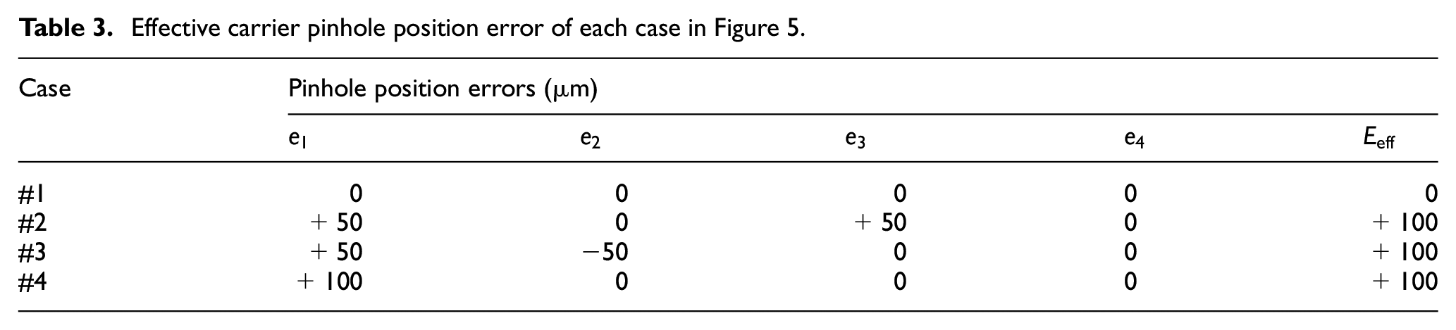
The carrier used in this study had a carrier pinhole position error of +50 µm proposed by the manufacturer. To assume that the load-sharing characteristics of the PGS greatly deteriorated, the doubled carrier pinhole position error was applied to pinhole 1 in this study such as Case 4 in Figure 6 and Table 3. In the simulation model, the error was realized by

PGS model and angle of pin 1 deformed by pinhole position error.
Mesh load factor
The load-sharing characteristics of a PGS can be evaluated using the mesh load factor Kγ presented by ANSI/AGMA 6123-B06, 26 as follows equation (2). For an ideal PGS, Kγ is unity because the input power is equally distributed to each planet gear. However, with non-torque loads and carrier pinhole position errors, Kγ becomes larger than unity. In this study, the torque transmitted to each planet pin was calculated using the simulation models and Kγ of the PGS was computed. Kγ becomes smaller according to the floating effect because the sun and ring gears float more freely with increasing the radial clearance between the gear and its shaft. When the floating effect increased enough for Kγ to converge to a specific value, the PGS was defined as being in the full floating state. A PGS with half the radial clearance as the PGS in the full floating state was defined as being in the half floating state

Gear rating
There are several standards to calculate the strength of spur gears and helical gears, but ISO 6336:2006 27 Method B is considered as the most reliable standard and generally used. This standard provides formulas for pitting resistance and bending failure of spur gears and helical gears as follows

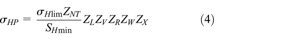


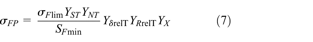

Most of factors used in equations (3)−(8) were calculated by Method B of ISO 6336; however, the application factor and the face load factor for contact stress should be determined by the design engineer. Table 4 lists the application factor, the allowable stress numbers of contact and bending fatigue strength, and the minimum required safety factors for pitting and bending. In this study, the face load factor for contact stress was accurately computed by considering all the elastic deflections of components using the FEM. The allowable stress numbers of contact and bending fatigue strength for the PGS were based on 18CrNiMo7 which is case-hardened steel. The minimum required safety factors for pitting and bending were based on the ISO 6336 (see Table 4).
Factors for gear strength calculation.

Load-sharing characteristics analysis
A quasi-static analysis method was used to analyze the effects of floating on the load-sharing characteristics of a PGS with only non-torque load (Models 1–4) and with both non-torque load and carrier pinhole position error (Models 5–8), respectively. The method is suitable to investigate the load-sharing characteristics of PGS with not only any planet number and support condition but also manufacturing errors. 28 The torque transmitted to each planet pin was calculated by rotating the carrier of the PGS by 45°. Despite the carrier rotation angle, the non-torque load was kept constant at 62 kN in the vertical direction, implying that the point where the maximum load was applied was also fixed. As previous studies reported, the power transmitted to each planet gear appeared as a periodic function depending on the carrier rotation angle whether only non-torque load or both non-torque load and carrier pinhole position error were considered.6,17 Furthermore, because the actual carrier pinhole position error of the PGS was 50 µm presented by the manufacturer, an error of +100 µm was applied to pinhole 1 to assume the worst load-sharing condition.
PGS with only non-torque load
Figure 8 shows the calculation results of the torque transmitted to each planet pin for a PGS (Model 1) without any floating member. Considering the influence of the non-torque load on the gearbox at the system level, the torque fluctuated depending on the position of the planet pin. The value of Kγ for Model 1 was 1.09 irrespective of the carrier rotation angle. The maximum and minimum torques transmitted to each planet pin were 481.50 and 402.70 Nm, respectively. A slight difference was observed in the maximum and minimum values according to the planet pins due to some numerical errors, and it is suggested that there was no actual difference.

Torque transmitted to each planet pin in Model 1.
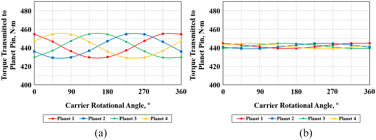
In Model 2, it was found that sun gear floating can be used to improve the load-sharing characteristics of the PGS. As the floating effect of the sun gear increased, Kγ converged to 1.00. When the PGS reached the full floating state, the clearance between the sun gear and sun gear shaft was 100 µm. Figure 9 shows the calculation results of the torque transmitted to each planet pin when the sun gear was in the half and full floating states. The value of Kγ was 1.03 in the sun gear half floating state, and the torques transmitted to each planet pin were 455.46, 444.80, 428.32, and 439.27 Nm. The planet pin with the highest torque delivered 106% of the torque delivered by the planet pin with the lowest torque. In the sun gear full floating state, Kγ was 1.00 because the load of the PGS was divided uniformly. The analysis results of Model 2 indicated that sun gear floating can be used to uniformly divide the load of the PGS with a non-torque load when there is no carrier pinhole position error.

Torque transmitted to each planet pin in Model 2: (a) sun gear half floating and (b) sun gear full floating.
In Model 3, it was found that ring gear floating can be used to improve the load-sharing characteristics of the PGS. As the floating effect of the ring gear increased, Kγ converged to 1.00. When the PGS reached the full floating state, the clearance between the ring gear and housing was 100 µm. This was consistent with the clearance when the PGS reached the sun gear full floating state. Figure 10 shows the calculation results of the torque transmitted to each planet pin when the ring gear was in the half and full floating states. The value of Kγ was 1.03 in the ring gear half floating state, and the torques transmitted to each planet gear pin were 454.79, 441.07, 429.21, and 442.80 Nm. The planet pin with the highest torque delivered 106% of the torque delivered by the planet pin with the lowest torque. In the ring gear full floating state, Kγ was 1.00 because the load of the PGS was divided uniformly. The analysis results of Model 3 indicated that ring gear floating can be used to uniformly divide the load of a PGS with a non-torque load when there is no carrier pinhole position error. Furthermore, irrespective of the type of floating member, full floating had the same effect on the load-sharing characteristics of a PGS, consistent with Singh, 7 and Kγ improved to 1.03 in the half floating state.

Torque transmitted to each planet pin in Model 3: (a) ring gear half floating and (b) ring gear full floating.
In Model 4, it was found that both sun gear floating and ring gear floating can be used together to improve the load-sharing characteristics of the PGS. As the floating effect of both gears increased, Kγ converged to 1.00 and the PGS reached the full floating state. The floating effects of both gears increased by the same amount. When the PGS reached the full floating state, the clearances between the sun gear and sun gear shaft and between the ring gear and housing were 80 µm. Figure 11 shows the calculation results of the torque transmitted to each planet pin when the sun gear and ring gear were in the half and full floating states. The value of Kγ was 1.03 in the half floating state of the sun gear and ring gear, and the torques transmitted to each planet pin were 455.04, 446.46, 429.41, and 436.94 Nm. The planet pin with the highest torque transmitted 106% of the torque transmitted by the planet pin with the lowest torque. The value of Kγ was 1.00 in the full floating state of the sun gear and ring gear because the load on the PGS was uniformly divided.
Torque transmitted to each planet pin in Model 4: (a) sun gear and ring gear half floating and (b) sun gear and ring gear full floating.
Although the total clearance required for the system was similar irrespective of the number of floating members, full floating can be implemented with smaller clearances for each floating member when two floating members were used as shown in Figure 12. This is consistent with the results of Chung et al. 23 The difference between the maximum and minimum torques transmitted to the planet pins for sun gear full floating and ring gear full floating was 1.72 Nm whereas that for sun gear and ring gear full floating was 5.68 Nm. In other words, the difference between the maximum and minimum torques transmitted to each planet pin when two members were fully floating was 3.3 times the difference when only one member was fully floating. However, for sun gear and ring gear full floating, Kγ was still 1.00 because the difference was very small compared to the torque transmitted to each planet pin.

Mesh load factor according to the clearance size when the PGS is with only non-torque load.
PGS with both non-torque load and carrier pinhole position error
Figure 13 shows the calculation results of the torque transmitted to each planet pin for a PGS (Model 5) without a floating member. Kγ showed the maximum value of 1.70 when the carrier in Model 5 was rotated by 0°, thereby representing a 56% increase in comparison to the result of Model 1. When Kγ was 1.70, the torques transmitted to each planet pin were 767.82, 288.77, 448.34, and 299.13 Nm. Planet pin 1 with the highest torque transmitted 266% of the torque transmitted by planet pin 2 with the lowest torque. Despite the carrier rotation angle, the largest torque was transmitted to planet pin 1, to which the carrier pinhole position error was applied, and the torque transmitted to planet pin 3, placed diagonally to planet pin 1, was larger than those transmitted to planet pins 2 and 4. The torques transmitted to planet pins 2 and 4 were relatively small because planet pin 1 with the carrier pinhole position error in the (+) direction contacted the sun gear and ring gear before the other planet gears, and the heaviest load was applied to this pin. Therefore, planet pin 3 on the opposite site of planet pin 1 bores a relatively larger load than planet pins 2 and 4.

Torque transmitted to each planet pin in Model 5.
The load-sharing characteristics of a PGS were studied in Park et al. 6 using a radial force and carrier pinhole position errors, and the maximum torque was found to be transmitted alternatively to planet pins 1 and 4 according to the carrier rotation angle. However, in this study, considering the effects of non-torque load and carrier pinhole position errors on the PGS at the system level, the maximum torque was always transmitted to planet pin 1, to which the carrier pinhole position error was applied, irrespective of the carrier rotation angle. This was because the input torque to the reduction gearbox used as a final drive was very small compared to the input torque to the gearbox of a wind turbine. As the input torque was decreased, the influence of carrier pinhole position error on the load-sharing characteristics of the PGS increased.6,24 The analysis results of Model 5 indicated that one planet pin with a carrier pinhole position error transmitted much larger torque than the others, and the value of Kγ of the reduction gearbox used in the electric forklift was large.
The analysis results of Model 6 indicated that sun gear floating can be used to improve the load-sharing characteristics of the PGS. As the floating effect of the sun gear increased, Kγ converged to 1.36. When the PGS reached the full floating state, the clearance between the sun gear and sun gear shaft was 300 µm. In comparison to the results of Model 2, Kγ increased by 36%. Figure 14 shows the calculation results of the torque transmitted to each planet pin when the sun gear was in the half and full floating states. The value of Kγ was 1.52 in the sun gear half floating state, and the torques transmitted to each planet pin were 670.97, 270.41, 544.05, and 282.44 Nm. Planet pin 1 with the highest torque transmitted 248% of the torque transmitted by planet pin 2 with the lowest torque. The value of Kγ was 1.36 in the sun gear full floating state, and the torques transmitted to each planet pin were 610.07, 286.27, 603.33, and 297.38 Nm. Planet pin 1 with the highest torque transmitted 248% of the torque transmitted by planet pin 2 with the lowest torque. Although a floating sun gear was applied, the maximum torque was transmitted to planet pin 1 irrespective of the carrier rotation angle. However, as the floating effect increased, the effect of carrier pinhole position error as well as the difference between the torques transmitted to the diagonally opposite planet pins decreased. The analysis results of Model 6 indicated that even if the clearance between the sun gear and sun gear shaft increased, Kγ could not converge to unity when both non-torque load and carrier pinhole position error were considered. However, the 20% reduction in Kγ in comparison to that in the non-floating model (Model 5) suggested that sun gear floating effectively improves the load-sharing characteristics of the PGS.

Torque transmitted to each planet pin in Model 6: (a) sun gear half floating and (b) sun gear full floating.
The analysis results of Model 7 indicated that ring gear floating can be used to improve the load-sharing characteristics of the PGS. As the floating effect of the ring gear was increased, Kγ converged to 1.36 and the ring gear reached the full floating state. This was the same as Kγ when the sun gear reached the full floating state. Furthermore, the clearance between the ring gear and housing was 300 µm. In comparison to the results of Model 3, Kγ increased by 36%. Figure 15 shows the calculation results of the torque transmitted to each planet pin when the ring gear was in the half and full floating states. The value of Kγ was 1.49 in the ring gear half floating state, and the torques transmitted to each planet pin were 670.70, 291.97, 543.99, and 294.82 Nm. Planet pin 1 with the highest torque transmitted 230% of the torque transmitted by planet pin 2 with the lowest torque. The value of Kγ was 1.36 in the ring gear full floating state, and the torques transmitted to each planet pin were 609.20, 295.42, 604.16, and 287.04 Nm. Planet pin 1 with the highest torque transmitted 212% of the torque transmitted by planet pin 4 with the lowest torque.

Torque transmitted to each planet pin in Model 7: (a) ring gear half floating and (b) ring gear full floating.
Although a floating ring gear was applied, the maximum torque was transmitted to planet pin 1 despite the carrier rotation angle. However, as the floating effect increased, the effect of carrier pinhole position error as well as the difference between the torques transmitted to the opposite planet pins decreased. This tendency was consistent with the results of the model with the floating sun gear (Model 6). The load-sharing characteristics of the PGS were better improved in the ring gear half floating state than in the sun gear half floating state. However, the difference between Kγ of both cases was not remarkably large. In Model 7, the non-torque load and carrier pinhole position error were considered. In comparison to the results for the PGS with only non-torque load, Kγ did not reach 1.00 even if ring gear full floating was used. However, compared with the results of the non-floating model (Model 5), Kγ was reduced by 20%. Models 6 and 7 showed that the type of floating member did not influence the effect of full floating on the load-sharing characteristic of the PGS; this was consistent with the results reported by Singh (2010).
The analysis results of Model 8 indicated that both sun gear and ring gear floating can be used together to improve the load-sharing characteristics of the PGS. As the floating effect of both gears increased, Kγ converged to 1.35 and the PGS reached the full floating state. It should be noted that the floating effects of both gears increased by the same amount. When the PGS reached the full floating state, the clearance between the sun and ring gears and their respective gear shafts was 160 µm. In comparison to the results of Model 4, Kγ increased by 35%. Figure 16 shows the calculation results of the torque transmitted to each planet pin when the sun gear and ring gear were in the half and full floating states. The value of Kγ was 1.48 in the half floating state of the sun gear and ring gear, and the torques transmitted to each planet pin were 664.59, 290.81, 550.20, and 296.22 Nm. Planet pin 1 with the highest torque transmitted 229% of the torque transmitted by planet pin 2 with the lowest torque. The value of Kγ was 1.35 in the full floating state of the sun gear and ring gear, and the torques transmitted to each planet pin were 609.27, 293.18, 606.06, and 294.25 Nm. Planet pin 1 with the highest torque transmitted 208% of the torque transmitted by planet pin 2 with the lowest torque. Although the floating effect increased, the maximum torque was transmitted to planet pin 1 irrespective of the carrier rotation angle. However, the difference between the torques transmitted to the diagonally opposite planet pins gradually decreased with an increase in the floating effect as this gradually reduced the influence of carrier pinhole position error. Sun gear and ring gear half floating was slightly more effective in improving the load-sharing characteristics of the PGS than sun gear half floating or ring gear half floating. The analysis results of Model 8 indicated that even if the PGS reached the sun gear and ring gear full floating state, Kγ did not reach 1.00 when both non-torque load and carrier pinhole position errors were considered. Similar to a PGS with a non-torque load, the PGS with a non-torque load and carrier pinhole position errors reached the full floating state with smaller clearance for each floating member when two floating members were used. In addition, the total clearance required for the system was similar despite the number of floating members. However, the effect of ring gear half floating or sun and ring gear half floating was slightly larger than that of sun gear half floating.

Torque transmitted to each planet pin in Model 8: (a) sun gear and ring gear half floating and (b) sun gear and ring gear full floating.
As same as the results of PGS with only non-torque load, Figure 17 shows that the total clearance required for the system was similar irrespective of the number of floating members and full floating can be implemented with smaller clearances for each floating member when two floating members were used. The values of Kγ for the ring gear floating model were numerically calculated as similar as those for the sun floating model. However, Kγ did not converge to 1.00 even if floating was increased continuously when the carrier pinhole position errors existed. This is because the backlash between the sun gear and planet gear and the planet gear and ring gear is limited. The floating member improved the load-sharing characteristics by changing the position of the gear mesh when uneven load sharing occurred. Thus, the floating members were limited in their freedom of motion owing to the backlash between gears, which was determined by the gear geometry. Under the backlash condition of the PGS used in this study, Kγ could be improved to 1.35 by the floating effect and it would be closer to unity with increasing the backlash.
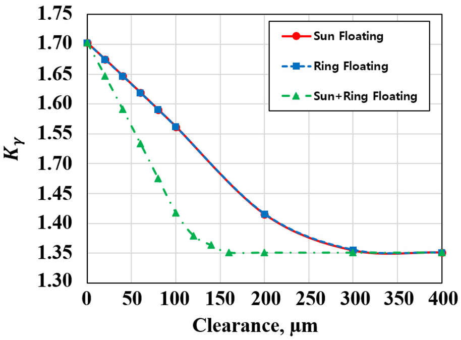
Mesh load factor according to the clearance size when the PGS is with both non-torque load and carrier pinhole position error.
Load distribution in gear meshes
In all simulation models, the maximum contact stress,
Maximum contact stress and load distribution factor of sun-planet meshes.

Maximum contact stress and load distribution factor of ring-planet meshes.


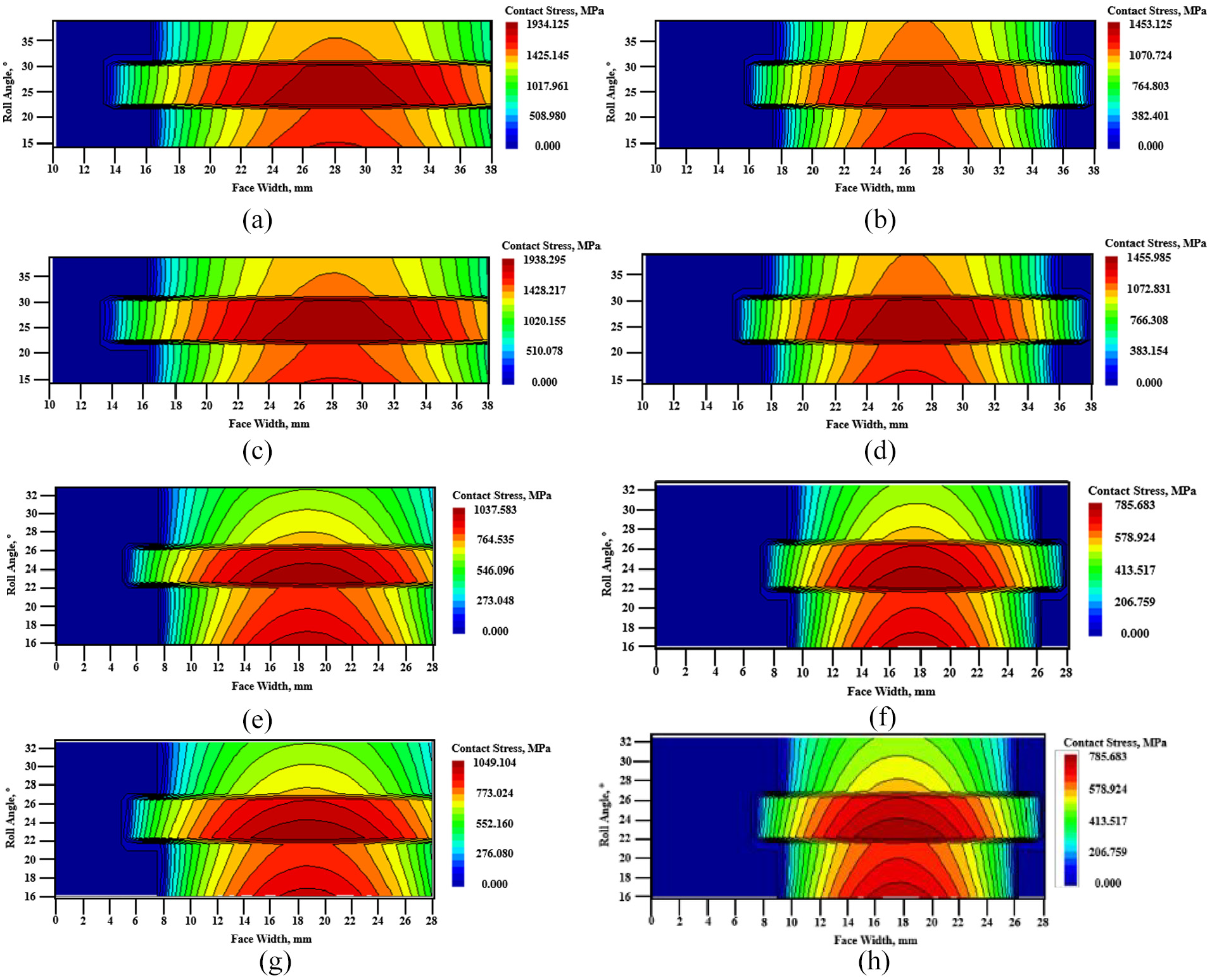
Tooth contact stress of all gear meshes in PGS of Model 5: (a) sun-planet 1 mesh, (b) sun-planet 2 mesh, (c) sun-planet 3 mesh, (d) sun-planet 4 mesh, (e) ring-planet 1 mesh, (f) ring-planet 2 mesh, (g) ring-planet 3 mesh, and (h) ring-planet 4 mesh.
Tooth contact stress of all gear meshes in PGS of Model 8: (a) sun-planet 1 mesh, (b) sun-planet 2 mesh, (c) sun-planet 3 mesh, (d) sun-planet 4 mesh, (e) ring-planet 1 mesh, (f) ring-planet 2 mesh, (g) ring-planet 3 mesh, and (h) ring-planet 4 mesh.
It was also found that using both sun gear floating and ring gear floating was more effective way to decrease the variance of
Safety factors for contact and bending stress
The effects of floating on the strength of PGS with only non-torque load and with both non-torque load and carrier pinhole position error are listed in Tables 7 and 8, respectively. The increase ratio of strength for the sun gear was similar to the value for the planet gear because the strength of planet gears in sun-planet mesh was worse than that in ring-planet mesh. In terms of gear failure, the bending stress is more critical than the contact stress. It was worthwhile to confirm that the safety factors for bending were much more improved than those for pitting by floating effects.
Strength calculation results for PGS with only non-torque load.

Strength calculation results for PGS with both non-torque load and carrier pinhole position error.

As shown in Table 7, the sun gear of PGS with only non-torque load has the worst strength for both pitting and bending. However, its safety factors were already higher than unity even if the PGS was not in floating state. In the PGS with both non-torque load and carrier pinhole position error, the strength of all gears decreased when it was compared to the results for the PGS with only non-torque load. The sun gear has the worst strength for pitting, but the planet gear has for bending due to the carrier pinhole position error, as shown in Table 8. In addition, the bending safety factor of the planet gear for the PGS not in the floating state was lower than unity, which means that the original design did not satisfy the strength requirement. The significant results of this study are that the modified design in which the PGS is in full floating state has the higher bending safety factor of the planet gear than unity, so that it satisfies the strength requirement.
Conclusion
In this study, the effects of floating on the load-sharing characteristics and the strength of a PGS with a non-torque load and carrier pinhole position error were analytically investigated for the general reduction gearbox of an electric forklift. The ground reaction force due to the vehicle weight and workload was considered as the non-torque load. The carrier pinhole position error was applied to produce the worst effect on the load-sharing characteristics of the PGS. The load-sharing characteristics of the PGS were evaluated using Kγ. When using floating members for a PGS with a non-torque load, Kγ converged to 1.00. The torque transmitted to each planet pin was expressed as a periodic function depending on the carrier rotation angle. The value of Kγ for the non-floating model was 1.09. Furthermore, it converged to 1.03 in the half floating state and 1.00 in the full floating state irrespective of the type and number of floating members.
The load-sharing characteristics of a PGS with a non-torque load and carrier pinhole position error could be improved with floating; however, Kγ did not converge to 1.00. This was attributed to the backlash, determined by the gear geometry, that limited the floating effect. In comparison to the load-sharing characteristics of a PGS with only non-torque load, the torque transmitted to the planet pin was expressed as a periodic function depending on the carrier rotation angle. Although the maximum torque was always transmitted to planet pin 1, owing to the carrier pinhole position error, similar torques were transmitted to the opposite planet pins when the PGS reached the full floating state. The value of Kγ for the non-floating model was 1.70; this was 56% higher than that in the case when only the non-torque load was considered. Regardless of the type and number of floating members, the floating effect resulted in a similar improvement in the load-sharing characteristics of the PGS.
The load distribution of all gear meshes in the PGS was also improved by the floating effects. The floating effects significantly decreased the variance of the maximum contact stress and load distribution factor and moved the edge contact zone to the middle of the face width. Unlike the load-sharing characteristics, the type and number of floating members had different amount of improvements on the load distribution of gear meshes. Using multiple floating members seems to be more effective way to enhance the load distribution.
Compared with the results of PGS with only non-torque load, both safety factors of the PGS with both non-torque load and carrier pinhole position error were dramatically increased when it was in the full floating state. The original model that PGS was not in the floating state has the lower bending safety factor than the minimum safety factor presented in ISO 6336, but the modified model showed that the bending safety factor became higher than the minimum safety factor. These results imply that the load-sharing characteristics of a PGS used in a reduction gearbox for an electric forklift improve via floating despite the type and number of floating members and this increases the fuel efficiency; however, the floating effects are limited. Future work should therefore include follow-up work designed to verify the floating effect and limitation with experimental results. Improvement of the load-sharing characteristics of PGS with flexible pins will be also covered using the same model.
Footnotes
Appendix 1
Handling Editor: James Baldwin
Declaration of conflicting interests
The author(s) declared no potential conflicts of interest with respect to the research, authorship, and/or publication of this article.
Funding
The author(s) disclosed receipt of the following financial support for the research, authorship, and/or publication of this article: This research was financially supported by the Ministry of Trade, Industry and Energy (MOTIE), Korea, under the “Mechanical Industry Core Technology Development Program” (reference no. 20004583), supervised by the Korea Evaluation Institute of Industrial Technology (KEIT) and was conducted using the RomaxDESIGNER, Romax Technology Ltd.