
Abstract
The dynamics of spiral bevel gears have gained increasing importance due to concerns relating to noise and durability. This is because the mesh force acting on the gear teeth is amplified under dynamic conditions, potentially reducing the fatigue life of the gears. Furthermore, a sizable dynamic force can be transmitted to the housing, inducing structure-born gear whine. The elasticity of the bearings can influence the dynamics of spiral bevel gears. In this article, the finite element formulation of a spiral bevel geared rotor dynamic system is applied to investigate the influence of bearing elasticity on the dynamics of spiral bevel gears. The designs and configurations of rear axles are modeled and analyzed for real-world applications, to gain an enhanced practical understanding of the effect of bearing stiffness on spiral bevel gear dynamics.
Introduction
Spiral bevel gears are commonly used in automotive and aerospace applications to transmit power in non-parallel directions. A spiral bevel gear pair is a bevel gear pair with helical gear teeth. The main application of spiral bevel gears is in differentials of vehicles including electric vehicles, in which the direction of the drive from the drive shaft is turned 90° to drive the vehicle wheels. Compared with parallel axis gear like spur or helical gear, the spiral bevel gear has the personality of complex tooth geometry and time and spatial-varying gear meshing behavior. The dynamics of spiral bevel gears are of increasing importance since they are often plagued by aggravating noise, especially tonal whines at gear mesh frequencies. Furthermore, under dynamic conditions, the meshing force acting on the gear teeth is amplified, resulting in a potential reduction in the gear fatigue life. Hence, it is necessary to develop an in-depth understanding of the dynamics of spiral bevel gears and system resonance characteristics to design a more silent and durable driveline. Spiral bevel gear dynamic studies are not comprehensive, mainly due to two reasons. First, spiral bevel gears have more complicated geometry and unique time and spatial-varying mesh characteristics. Second, due to the flexibilities of integrated shafts and bearings, the participation of higher coupled degrees of freedom (DOFs) of motion brings additional complexities.
While spur or helical gear dynamics has been extensively studied, research on spiral bevel gear dynamics is still not mature. Existing studies on hypoid and spiral bevel gears are limited to simple analytical models of the gear mesh.1–9 Remmers 1 studied the mass-elastic model of rear axle gears with infinite mesh stiffness to predict the pinion resonance and conducted experiments to verify the vibration peak. Kiyono et al. 2 derived a general form of the equation of motion for free vibrations for a pair of bevel gears with 2 DOF. Cheng 3 developed the single-point spiral bevel gear mesh-coupling model based on both unloaded and loaded exact gear tooth contact analysis. The spiral bevel gear mesh model was then applied to enable the development of a multiple DOFs, lumped parameter dynamic model of the spiral bevel geared rotor system for both linear time-invariant and nonlinear time-varying analysis. Wang 4 proposed a multi-point hypoid gear mesh-coupling model based on the single-point gear mesh-coupling model developed by Cheng 3 and applied the new gear mesh model to enable the modeling and analysis of hypoid and spiral bevel geared rotor system dynamics. Jiang 5 analyzed the nonlinear phenomenon by applying both analytical and numerical solutions to a low DOF torsional dynamic model. Wang 6 further studied the influence of nonlinear and time-varying gear mesh parameters on the dynamic behavior of a hypoid and spiral gear pair. Peng and Lim7–9 used a multiple DOF dynamic model in which flexible springs support the pinion and ring gear. The aim was to investigate the influence of torque load on hypoid and spiral bevel gear nonlinear time-varying dynamic responses, coupled multi-body dynamics and vibration, and the influence of gear assembly error, gear eccentricity, and gear mesh sliding friction on hypoid and spiral bevel gear dynamics.
However, previous research on hypoid and spiral bevel gear dynamics is limited. The previous work on hypoid and spiral bevel gear dynamics has focused on gear pair mesh dynamics with limited DOFs. Moreover, the flexibility of the gear-shaft-bearing structure is ignored or simply represented by supporting springs of assumed stiffness, which is not practical and can have a significant influence on the validity of the analysis. Although the design and configuration of bearings vary for different industrial applications, sufficient attention has not been paid to bearing elasticity with regard to the dynamics of a complete spiral bevel geared rotor system. Thus, this article focuses on the influence of the bearing elasticity on the dynamic responses of the hypoid and spiral bevel geared systems for industrial applications.
Dynamic model
A dynamic finite element model of the spiral bevel geared system proposed by Hua et al. 10 is shown in Figure 1. This considers the shaft-bearing designs and configurations, which will be used in this study and are briefly discussed. The complete modeling details can be found in the paper of Hua et al. 10 The driveline system for industrial applications is modeled in this article. The complete system model shown in Figure 1 has 17 nodes. The mass and moment of inertia of the pinion and ring gear are separately lumped at one node at the center of gravity (CG) using a gear mesh coupling between the two nodes. The mass and moment of inertia of the differential are lumped at one node. The pinion shaft and gear shaft are modeled using beam elements, and consistent mass matrices are applied for beam elements.

Finite element modeling of spiral bevel geared rotor dynamics.
Several different approaches to calculate bearing stiffness are available in the literature. For example, Lim and Singh11,12 reported an analytical formulation for calculating bearing stiffness in the form of 6 × 6 stiffness matrix suitable for dynamics analysis. Concli et al.
13
also reported both numerical and analytical techniques14–16 to calculate the bearing stiffness. In this study, the bearing stiffness formulation developed by Lim and Singh11,12 is applied to calculate the
The mass and stiffness matrices for the entire dynamic system are derived as follows

where
The stiffness matrices of the whole system are derived as follows

where
The system proportional damping is calculated in this model as follows

where
The excitation of the whole system could be written as follows

where
The mesh stiffness
where
The equation of motion of the full spiral bevel geared rotor system could be written as

The dynamic response of the pinion head
The dynamic transmission error can be formulated as

The dynamic mesh force in the line-of-action direction could be formulated as follows

where
The dynamic mesh force response acting at the gear teeth is the most critical indictor for the spiral bevel gear dynamic characteristics, and therefore the dynamic mesh force is mainly investigated in this article. The dynamic mesh force is calculated based on equations (1)–(8) and plotted as a function of gear mesh frequency in the frequency domain.
Influence of roller bearing elasticity
Shaft-bearing configurations
In real-world practice, various types of shaft-bearing configurations of rear axles are used. For instance, in light- or medium-duty rear axles, the pinion is generally overhung and mounted with two roller bearings. In contrast, for medium- or heavy-duty rear axles, the pinion is often straddle mounted with three roller bearings, as shown in Figure 2. The significant difference between the two configurations is that there is a straight roller bearing (Bearing #0) used to support the rear end of the pinion in the straddle mounted pinion design. The straight roller bearing (Bearing #0) is designed to support the radial load rather than a thrust load. In this article, it is assumed that the only difference between the two designs lies in the straight roller bearing (Bearing #0).

(a) Straddle mounted pinion with three bearings and (b) overhung mounted pinion with two bearings.
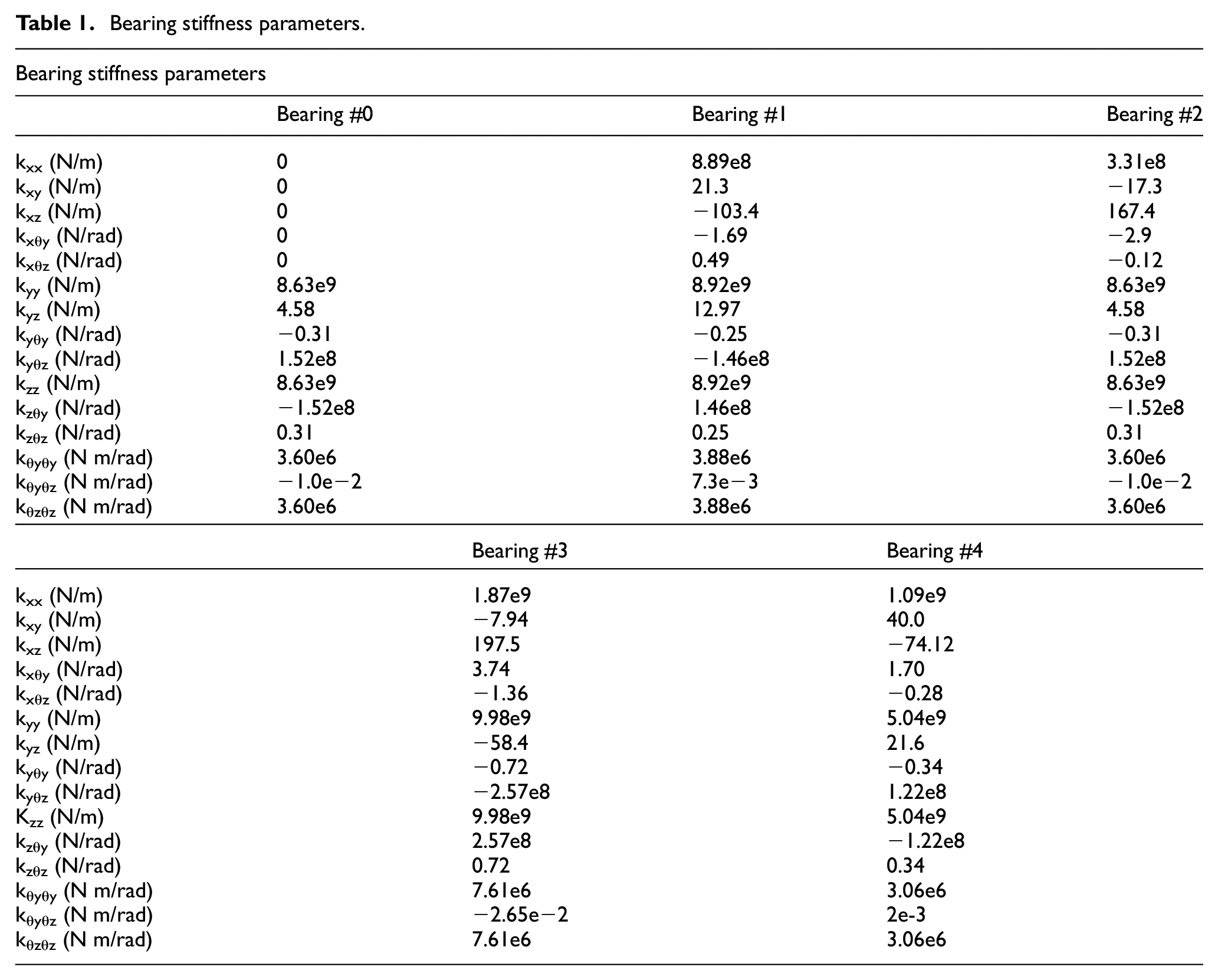
This article focuses on investigating the influence of the bearing elasticity of the two types of pinion configurations on the vibrations and dynamics of the spiral bevel geared rotor system, using the finite element–based dynamic model. The investigation is based on real-world gear-shaft-bearing design and operating conditions. Baseline bearing stiffness parameters used in this study are demonstrated in Table 1. The change in roller bearing radial stiffness, axial stiffness, and bending stiffness are also investigated. Only the influence of roller bearing radial stiffness and axial stiffness is demonstrated in this article since the influence of roller bearing radial stiffness and bearing axial stiffness on the dynamic mesh force is much more significant than the influence of the roller bearing bending stiffness.
Bearing stiffness parameters.
Effect of roller bearing radial stiffness
The comparison of the dynamic mesh forces for the spiral bevel geared rotor systems is demonstrated in Figure 3. The system comprises a straddle mounted pinion, respectively, with a baseline radial stiffness of Bearing #1, 1/3rd of the baseline radial stiffness of Bearing #1, 1/9th of the baseline radial stiffness of Bearing #1, and 1/100th of the baseline radial stiffness of Bearing #1. As the radial stiffness of Bearing #1 departs from the baseline (initial) radial stiffness, three main peaks of dynamic mesh force, respectively, at approximately 735, 835, and 1325 Hz begin to deviate. It is observed that the mode shapes of the three peaks are the critical pinion torsional mode coupled to the strong pinion transverse and bending motions due to pinion shaft bending. 17 The changes in the three main peaks demonstrate that the frequencies consistently and slightly decrease, the magnitude of the peak at 735 Hz consistently and slightly increases, and the magnitudes of the other two peaks at 835 and 1325 Hz consistently and slightly decrease, respectively. The underlying physics behind this phenomenon is that the decrease in the radial stiffness of Bearing #1 directly influences the pinion shaft bending modes, which leads to a change in the pinion torsional modes coupled to these pinion shaft bending modes, and then leads to a change in the dynamic mesh force responses strongly associated with these modes, that is, the three main peaks, respectively, at approximately 735, 835, and 1325 Hz. Since the pinion shaft is supported by three roller bearings, a change in the single radial stiffness of Bearing #1 does not significantly influence the pinion shaft bending modes; therefore, pinion torsion modes coupled to pinion shaft bending modes, or dynamic mesh force responses associated with these modes. Figure 4 demonstrates the comparison of the dynamic mesh forces of the spiral bevel geared rotor systems with straddle mounted pinion with the baseline radial stiffness of Bearing #2, 1/3rd of the baseline radial stiffness of Bearing #2, 1/9th of the baseline radial stiffness of Bearing #2, and 1/100th of the baseline radial stiffness of Bearing #2. The dynamic mesh force responses corresponding to the four cases of different radial stiffness of Bearing #2 generally overlap, including the three main peaks at approximately 735, 835, and 1325 Hz, respectively. Clearly, the qualitative influence of radial stiffness of Bearing #2 on the dynamic mesh force is minor, less significant than the influence of the radial stiffness of Bearing #1. The comparison of the dynamic mesh forces of spiral bevel geared rotor systems with straddle mounted pinion with baseline radial stiffness of Bearing #0, 1/3rd of the baseline radial stiffness of Bearing #0, 1/9th of the baseline radial stiffness of Bearing #0, and 1/100th of the baseline radial stiffness of Bearing #0 is demonstrated in Figure 5. Qualitatively, the influence of the radial stiffness of Bearing #0 on the dynamic mesh force is similar to the influence of the radial stiffness of Bearing #1, which is moderate while more significant than the influence of the radial stiffness of Bearing #2. In general, the change in the radial stiffness of individual bearings, that is, Bearing #0, #1, and #2, of the straddle mounted pinion does not have a significant influence on the dynamic mesh force response.

Comparison of dynamic mesh forces of spiral bevel geared rotor systems with straddle mounted pinion with , baseline radial stiffness of Bearing #1;  , 1/3rd of the baseline radial stiffness of Bearing #1;
  , 1/9th of the baseline radial stiffness of Bearing #1;
  , 1/100th of the baseline radial stiffness of Bearing #1.
Comparison of dynamic mesh forces of spiral bevel geared rotor systems with straddle mounted pinion with , baseline radial stiffness of Bearing #2; , 1/3rd of the baseline radial stiffness of Bearing #2; , 1/9th of the baseline radial stiffness of Bearing #2; , 1/100th of the baseline radial stiffness of Bearing #2.
Comparison of dynamic mesh forces of spiral bevel geared rotor systems with straddle mounted pinion with , baseline radial stiffness of Bearing #0; , 1/3rd of the baseline radial stiffness of Bearing #0; , 1/9th of the baseline radial stiffness of Bearing #0; , 1/100th of the of baseline radial stiffness of Bearing #0.
However, for the system with an overhung mounted pinion design in which the straight roller bearing is removed from the rear end of the pinion, the radial stiffness of individual bearings influences the dynamic mesh force response much more significantly. For instance, when the baseline radial stiffness of Bearing #1 is reduced to 1/3rd, 1/9th, and finally 1/100th, the three main peaks, respectively, at approximately 730, 800, and 1255 Hz consistently vary as shown in Figure 6. The qualitative trend in both frequency and magnitude of the three main peaks is similar to that of the case with the straddle mounted pinion design shown in Figure 3. In contrast, the quantitative change in both frequency and magnitude is much more significant. Figure 7 shows the comparison of the dynamic mesh forces of the spiral bevel geared rotor systems with overhung mounted pinion with baseline radial stiffness of Bearing #2, 1/3rd of the baseline radial stiffness of Bearing #2, 1/9th of the baseline radial stiffness of Bearing #2, and 1/100th of the baseline radial stiffness of Bearing #2. While the trend is similar, the influence of the radial stiffness of Bearing #2 is less significant than the influence of the radial stiffness of Bearing #1 on the dynamic mesh force shown in Figure 6. In addition, compared with the case with the straddle mounted pinion design shown in Figure 4 in which the radial stiffness of Bearing #2 has little influence on the dynamic mesh force response, the influence of the radial stiffness of Bearing #2 is more significant in the system with the overhung mounted pinion design. For the system with overhung mounted pinion design, the change in radial stiffness of individual bearings more significantly affects the modes in which the contributions of pinion shaft bending is significant and therefore influences the dynamic mesh force responses strongly associated with these modes, that is, the three main peaks at approximately 730, 800, and 1255 Hz, respectively.
Comparison of dynamic mesh forces of spiral bevel geared rotor systems with overhung mounted pinion with , baseline radial stiffness of Bearing #1; , 1/3rd of the baseline radial stiffness of Bearing #1;, 1/9th of the baseline radial stiffness of Bearing #1; , 1/100th of the baseline radial stiffness of Bearing #1.
Comparison of dynamic mesh forces of spiral bevel geared rotor systems with overhung mounted pinion with , baseline radial stiffness of Bearing #2; , 1/3rd of the baseline radial stiffness of Bearing #2; , 1/9th of the baseline radial stiffness of Bearing #2; , 1/100th of the baseline radial stiffness of Bearing #2.
Effect of roller bearing axial stiffness
In addition to radial stiffness, the axial stiffness of the roller bearing is also critical to the spiral bevel gear dynamics. Effect of softening the axial stiffness of Bearing #1 and Bearing #2 on the dynamic mesh forces of the spiral bevel geared rotor systems with the straddle mounted pinion configuration and overhung mounted pinion configuration is demonstrated in Figures 8–11. The effect of axial stiffness of Bearing #0 is not investigated since Bearing #0 is a straight roller bearing and its axial stiffness is always zero. Both axial stiffnesses of Bearing #1 and Bearing #2 significantly influence the dynamic mesh forces of the spiral bevel geared rotor systems with either overhung mounted pinion configuration or straddle mounted pinion configuration. In addition, similar to the effect of the radial stiffness, the axial stiffness of Bearing #1 has a larger impact on the dynamic mesh force than the axial stiffness of Bearing #2. As the axial stiffness of Bearing #1 or Bearing #2 decreases, the frequencies of the main peaks tend to decrease which is consistent with the trend of the effect of the radial stiffness on the dynamic mesh force; however, the trend of the magnitude of the main peaks is not consistent with the trend of the effect of the radial stiffness. For example, in Figures 8–11, the magnitude of the peak near 1300 Hz tends to increase as the bearing axial stiffness decreases while it decreases as the bearing radial stiffness decreases, as shown in Figures 3–7.
Comparison of dynamic mesh forces of spiral bevel geared rotor systems with straddle mounted pinion with , baseline axial stiffness of Bearing #1; , 1/3rd of the baseline axial stiffness of Bearing #1; , 1/9th of the baseline axial stiffness of Bearing #1; , 1/100th of the baseline axial stiffness of Bearing #1.
Comparison of dynamic mesh forces of spiral bevel geared rotor systems with straddle mounted pinion with , baseline axial stiffness of Bearing #2; , 1/3rd of the baseline axial stiffness of Bearing #2; , 1/9th of the baseline axial stiffness of Bearing #2; , 1/100th of the baseline axial stiffness of Bearing #2.
Comparison of dynamic mesh forces of spiral bevel geared rotor systems with overhung mounted pinion with , baseline axial stiffness of Bearing #1; , 1/3rd of the baseline axial stiffness of Bearing #1; , 1/9th of the baseline axial stiffness of Bearing #1; , 1/100th of the baseline axial stiffness of Bearing #1.
Comparison of dynamic mesh forces of spiral bevel geared rotor systems with overhung mounted pinion with , baseline axial stiffness of Bearing #2; , 1/3rd of the baseline axial stiffness of Bearing #2; , 1/9th of the baseline axial stiffness of Bearing #2; , 1/100th of the baseline axial stiffness of Bearing #2.
Conclusion
A finite element–based spiral bevel geared rotor dynamic system is employed to investigate the effect of the stiffness of roller bearing on the dynamic responses of spiral bevel geared systems for industrial applications. The results demonstrate that as the radial stiffnesses of individual roller bearings decrease from their original value, the influence on the dynamic mesh force response is more significant in systems with an overhung mounted pinion configuration, and less significant with a straddle mounted pinion configuration. It is observed that the influenced main peaks of the dynamic mesh force responses are all strongly coupled to the pinion shaft bending modes. The results also show that as the axial stiffnesses of the individual roller bearings decrease from their original value, a significant influence on the dynamic mesh force is observed in systems with either the overhung mounted pinion or straddle mounted pinion configurations. In general, the radial and axial stiffness of the tapered roller bearing mounted closer to the pinion has a more significant impact on the dynamic mesh force than that of the tapered roller bearing mounted farther away from the pinion. This investigation guides the design of roller bearings of rear axles from the viewpoint of spiral bevel gear dynamics and vibrations.
Footnotes
Handling Editor: James Baldwin
Declaration of conflicting interests
The author(s) declared no potential conflicts of interest with respect to the research, authorship, and/or publication of this article.
Funding
The author(s) received no financial support for the research, authorship, and/or publication of this article.