
Abstract
The axial and radial temperature distributions of an induction heating workpiece considerably impact the subsequent nitriding process. To obtain a satisfactory temperature distribution, an equal pitch coil, a variable pitch coil, and a variable radius coil were designed. Furthermore, an induction heating model that exhibits electromagnetic and temperature field coupling was established; thus, the effects of the current density and frequency on the heating efficiency and temperature distribution of the workpiece were analyzed and compared. In addition, an induction heating experiment was conducted to verify the model. According to the numerical results, the variable radius coil can reduce the axial temperature difference in comparison with equal pitch coil and variable pitch coil. Hence, the workpiece heated using the variable radius coil can achieve a better temperature distribution when compared with those heated by the equal pitch coil and variable pitch coil, with appropriate current density and current frequency values.
Introduction
The induction nitridation process1,2 is an efficient method for surface treatment of the magnetic metal material.3,4 Its unique heating technology is widely used in the surface treatment of metal materials 5 and welding. 6 Compared to traditional nitridation7,8 methods, it has a fast heating speed, 9 high efficiency,10,11 and the non-contact heating method makes it difficult to incorporate impure substances in the nitrided layer. 12 As shown in Figure 1, the workpiece can be rapidly heated under a radial temperature gradient using the induction heating method, thereby reducing the time required for heating and improving the production efficiency. When the temperature of the workpiece surface is uniform, the uneven hardness of the nitrided layer and uneven nitriding layer depth are reduced. 13 However, when the temperature difference between the workpiece surface and the core is large, nitrogen atoms are diffused into the core, thereby increasing the nitride layer thickness. 14 Therefore, it is very important to control the temperature distribution of the heated workpiece during the induction heating process. However, some challenges associated with the coil structure design15,16 and selection of parameters,17,18 including the heating time, current density, and current frequency, should be overcome during induction heating. Meanwhile, this process is complicated and relies on the trial-and-error method.

High-frequency induction nitriding equipment.
Thus, it is impossible to study the internal characteristics of the workpiece during induction heating, as it is difficult to measure the internal temperature distribution of the material. Therefore, finite element modeling is critical to understanding the fundamentals of the heating process.19–21 By simulating the distribution of temperature in the process of induction heating, it is helpful for better research and use of induction heating technology.22,23 Due to the complexity of the electromagnetic and thermal field coupling and the nonlinearity of the material parameters, the use of multiple algorithms in the temperature field solution process and model optimization process is involved,24–26 and researchers are studying the numerical solution of the induction heating temperature process. Kranjc et al. 27 investigated the effect of temperature-dependent material parameters on the temperature distribution accuracy of a heating cylinder. Although the nonlinearity of the relative magnetic permeability was not considered, the results obtained proved that the use of temperature-dependent parameters makes the simulation results more reliable. Song and Moon 28 analyzed an induction heating process to predict the temperature distribution of marine crankshaft forging. Considering the nonlinearity of the electromagnetic material properties, an equivalent circuit model of coupled electromagnetic and temperature fields was used to evaluate the effect of electrical material properties on the heating variables. Meanwhile, relative permeability was considered for the entire induction heating process. Hence, the above-mentioned induction heating model demonstrates the importance of temperature-dependent material parameters for the reliability of the entire simulation during induction heating. However, Han et al. 29 established a three-dimensional induction heating model. They performed numerical analysis on the current frequency and the distance between the coil and the weld, by varying the current density. The quality and temperature field of the weld were optimized by changing different parameters. In addition, Hadad et al. 30 modified the diameter of the crucible so that more material could be placed, to predict the efficiency of the secondary heating coil by numerical simulation. The results showed that the secondary heating coil can be successfully used to heat the step diameter crucible. Furthermore, Wang et al. 31 analyzed the induction heating process of a coil to obtain the temperature distribution of the gear rolling process, using numerical simulation. A better temperature distribution can be obtained using experimental and numerical simulations of the workpiece heated by the longitudinal coil, considering the influence of the coil shape on the temperature distribution. Thus, these studies have focused on coil heating parameters and the radial temperature difference of the workpiece. However, the influence of different coil structures on the axial temperature distribution of the workpiece located on the outermost surface as a key factor in nitriding heat treatment has been rarely studied.
Considering the major influence of the induction heating coil shape on the temperature distribution of the workpiece, this study investigates the effects of equal pitch coil (EPC), variable pitch coil (VPC), and variable radius coil (VRC) on the temperature distribution of the workpiece. The induction heating quality and production efficiency of the workpiece were quantitatively studied using different coil shapes and electromagnetic parameters. It can be observed that the induction heating quality and production efficiency of the workpiece during the nitriding process can be improved by designing a reasonable coil structure and selecting appropriate heating parameters. Furthermore, the VRC is used in the heating experiments to verify the established model. This study provides the basis for further application of the induction nitride heat treatment process and the subsequent optimization of the induction heating temperature field of metal materials exhibiting different sizes.
Mathematical model
Electromagnetic field
An electromagnetic field is described by a set of equations, known as Maxwell equations, as follows

where H is the magnetic field strength, J is the current density, D is the electric displacement vector, E is the electrical intensity, B is the magnetic flux density, ρ is the volume charge density, l is a closed curve, s is the surface bounded by l, and t is time.
Based on equation (1), the electromagnetic field in the numerical simulation of induction heating can be derived from the vector magnetic position A and scalar potential ϕ, which can be expressed by the Helmholtz equation
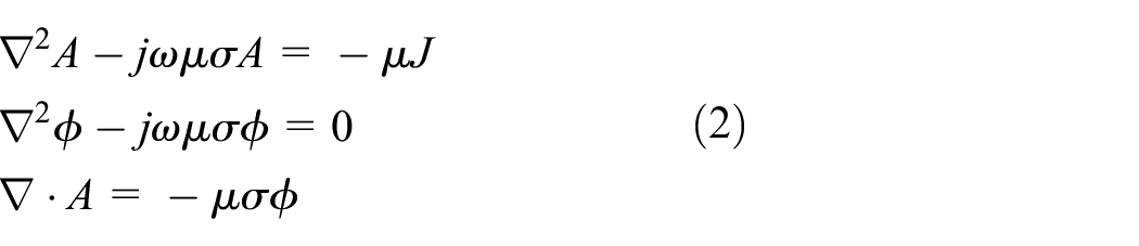
where J is the current density,
However, A and ϕ satisfy the boundary conditions at the interface S between the eddy current zone
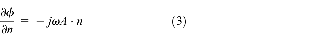
Meanwhile, the current induced by the eddy current zone can be obtained by

Satisfied at boundary Г

Furthermore, Green’s theorem (2) can be used as follows

where
Temperature field
Generally, the temperature distribution of a heated workpiece surface is of utmost importance in the study of the temperature field generated by induction heating. During the induction heating process of the workpiece, especially in the high-temperature zone near the heating zone surface, the temperature changes are severe. Thus, the relation between the thermal properties of the material and the temperature should be considered. Meanwhile, the temperature variation range of the workpiece during the heating process is large along the thickness direction. A large temperature gradient can also be observed. Therefore, to improve the calculation accuracy, a three-dimensional nonlinear transient heat conduction equation should be used to describe the temperature field T(x, y, z, t) during heating.
The three-dimensional nonlinear transient heat conduction can be controlled by the following differential equation
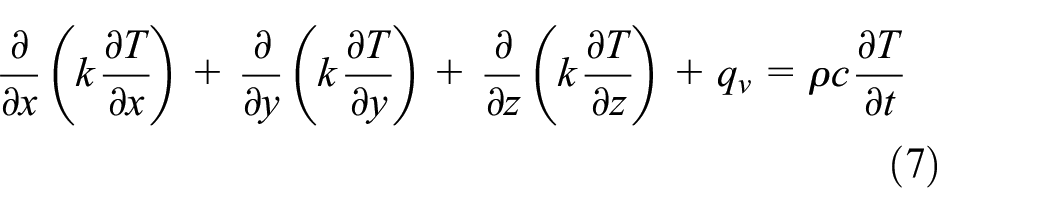
where
During induction heating, the induced eddy current acts as an internal heat source whose intensity can be controlled by the following differential equation

where
The boundary conditions of the workpiece surface are convection and radiation, expressed as

where
Finite element simulation
The finite element model of the induction heating of the EPC, VPC, and VRC is established using UG software. All three models are composed of coil and workpiece, as shown in Figure 2. The coils transmit high-frequency current and generate an alternating magnetic field that can induce eddy currents in the workpiece and then generate heat.
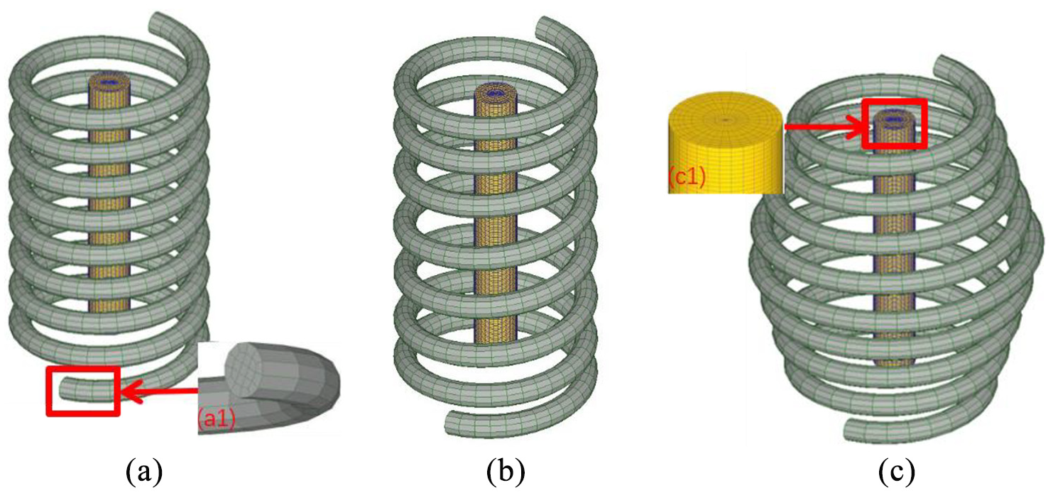
Mesh of three type of coils: (a) EPC, (b) VPC, and (c) VRC.
The chemical composition of the low-carbon steel distribution in the workpiece is shown in Table 1. Based on the surface temperature and cross-section temperature gradient requirements of material nitriding, the main parameters and dimensions of the three coils are determined and shown in Table 2. The material properties as a function of temperature are shown in Figure 3.
Chemical composition of steel (wt%).

Materials and dimensions of VPC, EPC, and VRC.

VPC: variable pitch coil; EPC: equal pitch coil; VRC: variable radius coil.

Temperature-dependent material constants of thermal and electromagnetic properties: (a) heat capacity, (b) thermal conductivity, (c) electrical conductivity, and (d) relative magnetic permeability.
The mesh of the three types of coils, obtained in a hexahedral form, is shown in Figure 2. Moreover, the workpiece is discretized by a hexahedral mesh, and the number of the elements is 6300. Furthermore, the boundary element method is used in the experiment to simulate the induction heating process. Compared to the FEM, the air domain model is not required. Therefore, the numerical simulation of the complex coil can be performed, with lower calculation amount and improved calculation precision. In case of the workpiece and coil, the workpiece is not in direct contact with the coil. The coil is assigned as the master, while the workpiece is assigned as the slave, such that the coil is the source of electromagnetic field for the workpiece.
The flow of magneto-thermal coupling calculation for the electromagnetic induction heating, using Deform software, is shown in Figure 4. The electromagnetic field and distribution of magnetic flux density can be calculated by introducing the model and determining the relative position of the workpiece to the coil. Furthermore, the induced eddy current generated in the workpiece can be estimated by calculating the alternating magnetic field generated by the coil; however, the electromagnetic heat generated on the workpiece can be estimated using the calculated induced eddy current. In the electromagnetic induction heating process, the electromagnetic heat is the heating source for the analysis of the thermal field. If the calculation converges, the update includes temperature-dependent material constants for relative permeability, resistivity, thermal conductivity, and specific heat, and the program proceeds to the next time step. However, if the calculation does not converge, the program proceeds to the next iteration step and performs the thermal analysis again. Once the temperature analysis required for heating is finished, the program ends.

Flowchart of the induction heating process coupled with electromagnetic and thermal field calculation.
Result and discussion
Influence of coil structure on heating efficiency
A simulation of the electromagnetic induction heating process with three coil structures is performed by selecting five points at equal intervals on the workpiece surface, to study the heating rate and axial temperature difference, as shown in Figure 5(a). The relation between the temperature of the selected points using different structural coils and heating time is shown in Figure 6. From the figure, the heating rate and temperature difference of the EPC significantly increase after the heating time exceeds 2 s. However, the temperature difference curve of the VPC and VRC gradually decreases. Meanwhile, the decreasing trend of the VRC is more prominent because the magnetic field distribution in each coil is a dynamic magnetic field that gradually changes along the coil rather than a steady-state magnetic field, as shown in Figure 7. As a result, the magnetic field distributed around the workpiece and the eddy current induces change dynamically, thereby resulting in a significant change in the heating rate of the workpiece at 2 s. Figure 6 shows that the magnetic field change in the EPC increases the axial temperature difference, while the magnetic field change in the VPC and VRC gradually decreases the temperature difference.

Schematic representation of the positions of five selected points: (a) axial selection and (b) radial selection.

Heating rate curve and temperature difference curve of different coil structures: (a) EPC, (b) VPC, and (c) VRC.

Magnetic field density map of different coil structures: (a) EPC, (b) VPC, and (c) VRC.
In addition, the temperature rise curves of the three coils are a fold line, because all parameters of the material are temperature-dependent curves. The magnetic field of each coil also changes during the induction heating process, as shown in Figure 7. As a result, the magnetic field density generated by the coil, as well as the rate of temperature rise, is large. Conversely, the magnetic field density produced by the coil is small, generating only a small amount of electromagnetic heat and resulting in a low rate of temperature rise. Meanwhile, the magnitude of the magnetic field density is related to the heating rate. If the magnetic field density is small, the heating efficiency of the coil is low during induction heating. Based on Figures 5 and 6, the magnetic field density using the EPC, VRC, and VPC is sequentially lowered. In addition, the heating time of the coils is sequentially increased. Therefore, the EPC is more efficient than the VRC and VPC during induction heating.
Influence of current density and current frequency on workpiece temperature distribution
During the nitriding process of the workpiece, the uniformities of the nitride layer hardness and the nitride layer depth are affected by the combined effects of axial and radial temperature distributions. If the temperature at a certain point on the workpiece surface is very high, the ammonia gas decomposes faster. As the decomposition rate of the ammonia becomes faster, the nitrogen potential and nitrogen content of the material surface reduce. As a result, the surface hardness of the nitride layer is lowered. In addition, the higher the nitriding temperature, the greater is the possibility of material deformation. Conversely, if the temperature at a point on the workpiece surface is very low, the depth of the nitride layer becomes shallow and the hardness is low. Defects in the nitride layer will affect the application of the workpiece in production, thereby reducing the wear resistance, corrosion resistance, and fatigue strength of the workpiece. The quality of the nitride layer is related to the temperature distribution of the workpiece. In addition, the process of inductive heating is used to heat the nitriding zone of the workpiece to ensure rapid heating and reduce the possibility of material deformation during nitriding. Herein, the temperature of each point in the axial direction of workpiece heating and the temperature difference and distribution of the workpiece heating radial point are used to quantify the heating quality (Figure 5). Meanwhile, the preset is set to ∼550°C before nitriding the workpiece.
Effect of current density on workpiece temperature distribution
Figure 10 shows that the surface axial and radial temperature differences of the EPC vary with the current density. There is a negative correlation between the axial temperature difference and the current density corresponding to the EPC and a significant positive correlation between the radial temperature difference and EPC current density. As a result, the higher the current density, the lower is the axial temperature difference and the greater is the radial temperature difference when the workpiece reaches a predetermined value. Moreover, Figure 8(a) shows that the temperature distribution of the axial points exhibits an inverse normal distribution trend, which increases and then decreases, because the presence of the EPC has a central effect and an end effect. In addition, Figure 7(a) shows that the magnetic field density at the middle and both the ends is considerably high. Because the magnetic field density in the middle is higher than the magnetic field density at the end, the temperature at point C of the material surface is higher than the temperature at other points. The trend of the temperature distribution at each point in Figure 8(a) shows that the intermediate effect gradually increases and the end effect gradually decreases as the current density gradually increases. Besides, Figure 9(a) shows that the core temperature of the material gradually decreases as the current density increases. When the current density reaches
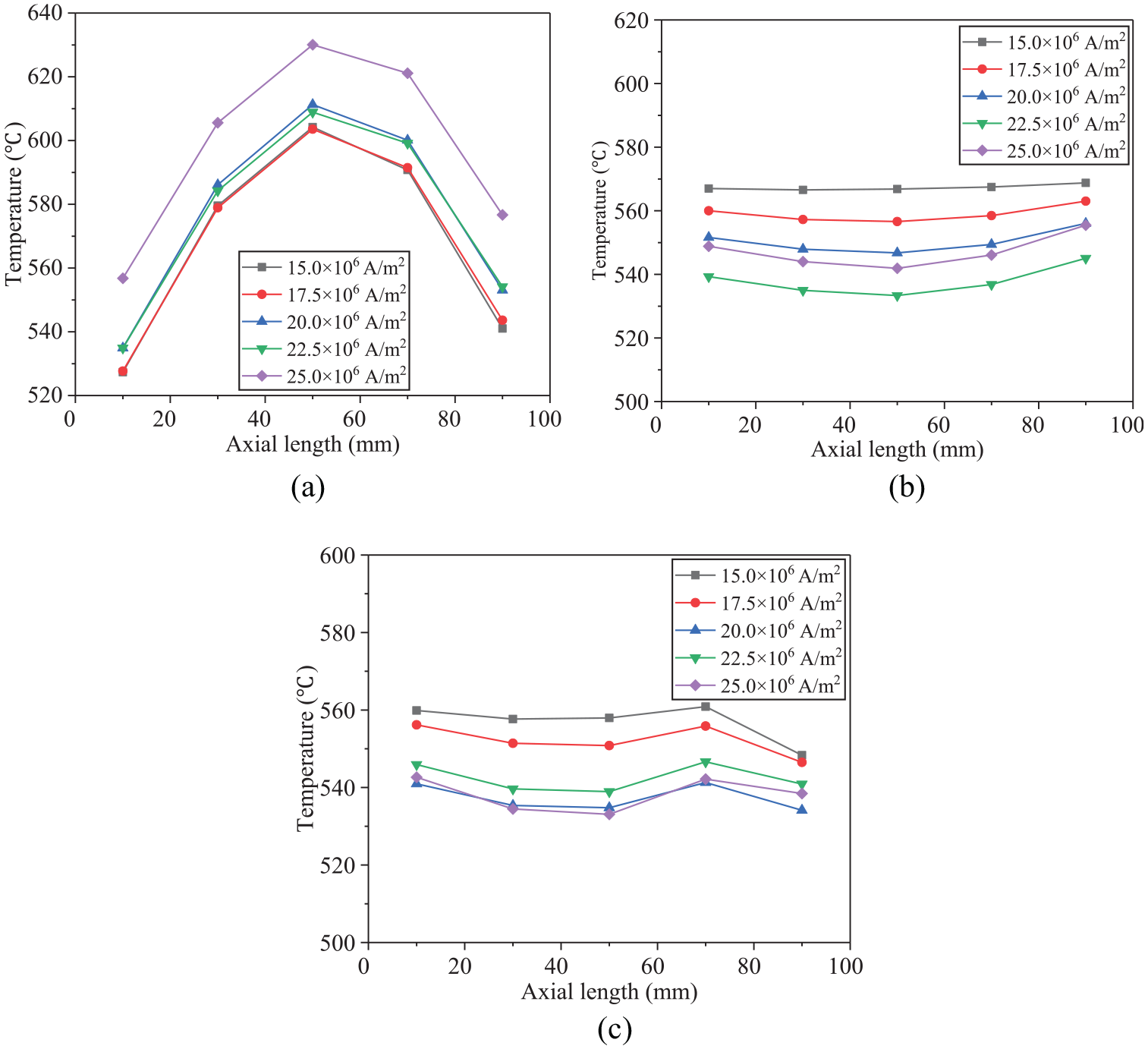
Axial temperature map of different currents: (a) EPC, (b) VPC, and (c) VRC.
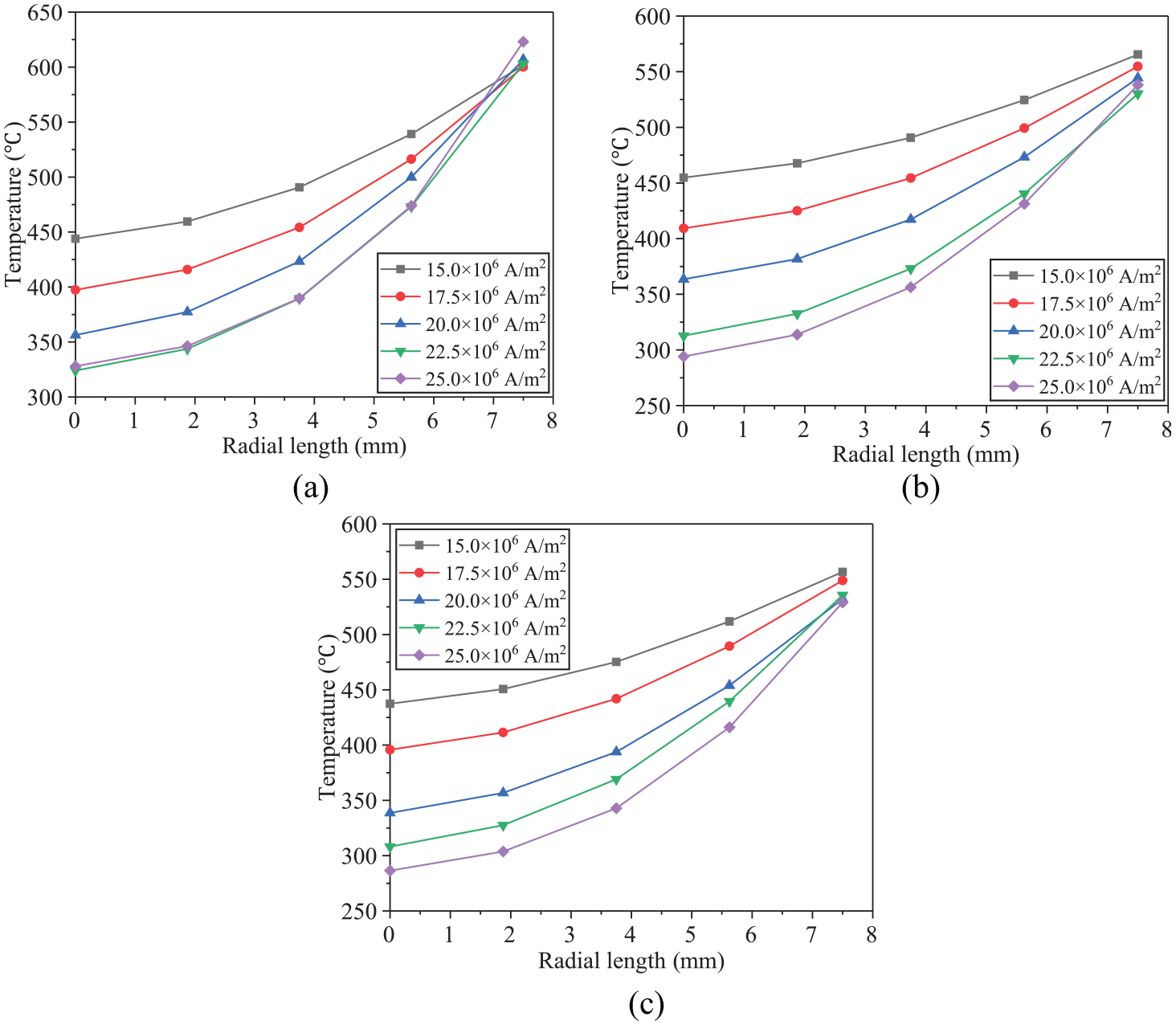
Radial temperature map of different currents: (a) EPC, (b) VPC, and (c) VRC.

Axial and radial temperature difference as a function of current density.
The heating quality between the three coils is compared. However, the VRC is used based on the axial temperature uniformity of the material and the radial temperature difference. When the coil is heated to the target temperature, the axial temperature difference is at least 7.14°C and the radial temperature difference is ∼196.56°C. Meanwhile, the axial minimum temperature difference for the EPC is 64.32°C, and the maximum radial temperature difference is 295.16°C. For the VPC, the minimum axial temperature difference is 2.21°C and the maximum radial temperature difference is 110.70°C. The results show that when the VPC is used, the magnetic field inside the coil is distributed in a gradient, so that the workpiece obtains a relatively uniform eddy current field. Compared to VRC and EPC, the temperature field at each point on the workpiece surface is more uniform. However, the radial temperature gradient is not prominent, as shown in Figure 11.

Minimum VPC axial temperature difference and radial temperature at a current density of
Effect of current frequency on workpiece temperature distribution
The axial and radial temperature distributions of the material vary with the current frequency, as shown in Figure 12. When the current frequency increases from 10 to 50 kHz, the radial temperature difference and frequency of the coils are positive. However, the axial temperature difference between the VRC and the VPC decreases and then increases with increasing frequency, while the EPC exhibits a slight increase and then decreases. Figure 13(a) shows that the intermediate effect of the EPC increases significantly with the frequency. Besides, Figure 14(b) and (c) shows that the central effect of the VPC and VRC is gradually reduced. It can be observed from Figure 14 that as the frequency increases, the temperature of the core of the material gradually decreases; furthermore, the temperature of the remaining two coil surfaces, except the EPC, tends to decrease gradually. This can be attributed to the existence of the central effect of the EPC.

Axial and radial temperature differences as a function of current frequency.

Radial point temperature maps of different current frequencies: (a) EPC, (b) VPC, and (c) VRC.
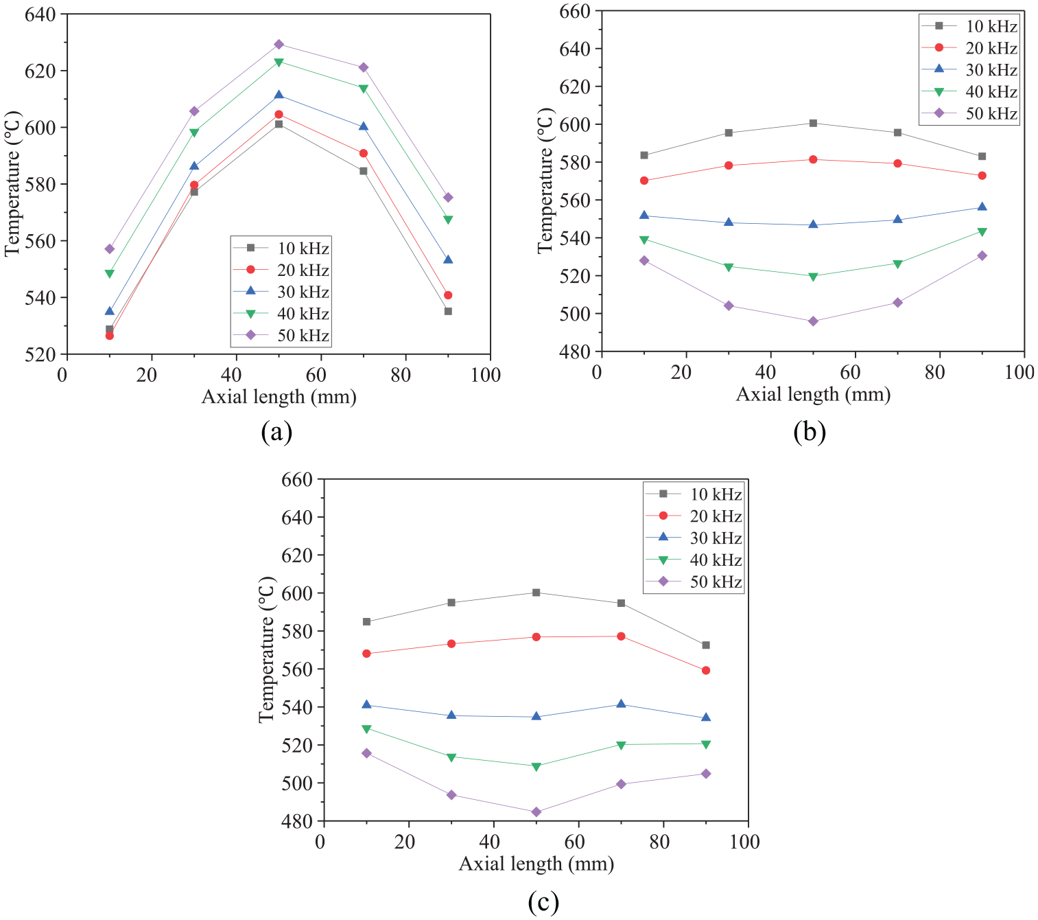
Axial temperature map of different current frequencies: (a) EPC, (b) VPC, and (c) VRC.
Based on the comparison of the axial and radial temperature differences among the three coils, when the current frequency of the VRC is increased from 10 to 30 kHz, the axial temperature difference decreases from 27.67 °C to 7.14 °C, which is a reduction of 74.2 %. However, the axial temperature difference of the VPC is reduced from 17.56°C to 9.28°C, with a decrease of 47.2 %. In addition, when the current frequency is increased from 10 to 50 kHz, the radial temperature difference corresponding to the VRC increases from 37.23°C to 243.24°C, which is an increase of 553.3%. Meanwhile, the radial temperature difference corresponding to the VPC increases from 35.54°C to 247.28°C, with an increase of 595.8 %. However, the radial temperature difference corresponding to the EPC increases from 51.08°C to 332.94°C with an increase of 551.8 %. Based on the comparison of the axial and radial temperature differences among the three coils, the current frequency affects the electromagnetic heat distribution. In the case where the current frequency is gradually increased, the heat generated by the eddy current is distributed in the outer layer of the workpiece, thereby resulting in an increase in the radial temperature difference. Thus, the VRC can achieve a better temperature distribution at the appropriate current density and current frequency, as shown in Figure 15.

Minimum VRC axial temperature difference and radial temperature at a current density of
Experimental validation
During the heating process, the high-frequency induction heating device supplies high-frequency harmonic current to the induction coil. The sample is placed on a porcelain boat and located inside a quartz tube. Due to the shielding of the coil and the limitation of the sealing condition of the quartz tube, the infrared thermal imager cannot display the temperature distribution on the sample surface. Therefore, an infrared thermometer is used to measure the temperature at different points. Moreover, the current and frequency values are measured simultaneously. Figure 16 shows the induction heating experiment of the VRC.

Induction heating experiment with VRC.
Furthermore, the temperature data of the workpiece heated by the VRC are extracted to verify the simulation results. The temperature distribution at different points on the surface between the simulation and the experimental results is compared. The temperature distribution simulation results at different points on the surface have the same trend as the experimental results, as shown in Figure 17. In addition, a quantitative analysis of the simulation and the experimental results is performed. The maximum error of the surface temperature distribution between the simulation and the experimental results is 6.03%. In addition, the temperature difference between the simulation and the experimental results is relatively small (∼4.86°C). The error is mainly due to the difference between finite element analysis and experiment. Therefore, the simulation results are verified to be reliable.

Comparisons between simulation and experimental results corresponding to the VRC.
Conclusion
In this article, the vacuum induction nitriding heating process of metal materials under three induction coil structures is quantitatively compared and studied. The conclusions can be presented as follows:
The magnetic field distributions are different among the EPC, VPC, and VRC, resulting in a different axial temperature distribution with respect to the outermost layer of the workpiece. As the central effect of the EPC is strong, the intermediate outermost layer temperature is higher than those of the VPC and VRC.
There is a positive correlation between the radial temperature difference and the current density. In addition, as the current density increases, the axial temperature difference corresponding to the VRC decreases and then increases. As the current density increases, the axial temperature difference of the EPC gradually decreases (to 64.31°C), whereas the axial temperature difference of the VPC gradually increases. The axial temperature difference of the VRC and VPC decreases and then increases. In an EPC, the axial temperature difference initially increases and subsequently decreases with increasing current frequency (to 72.14°C). The radial temperature of the three coils increases as the current frequency increases.
In the process of electromagnetic induction heating, the uneven temperature distribution of the workpiece axis is due to the central effect and end effect of induction heating. The temperature rise curve of temperature with time is a curve, which shows that the magnetic field distribution changes dynamically during induction heating.
The finite element model is verified by the heating experiment of the VRC. The axial temperature distribution between the simulation and the experimental results is compared. The simulation results agree well with the experimental results.
In summary, compared to the EPC and VPC, the VRC can reduce axial temperature differences, increase radial temperature differences, and increase heating efficiency. The workpiece heated by the VRC can achieve a better temperature distribution than that heated by the EPC and VPC, with proper current density and current frequency.
Footnotes
Handling Editor: James Baldwin
Declaration of conflicting interests
The author(s) declared no potential conflicts of interest with respect to the research, authorship, and/or publication of this article.
Funding
The author(s) disclosed receipt of the following financial support for the research, authorship, and/or publication of this article: This work was supported by the National Natural Science Foundation of China (Grant No. 51574096) and the Guizhou Talent Project (Grant No. [2017]5607).