
Abstract
During the rotary machine operation process, seemingly small amounts of abnormal vibration can often cause serious damage to the machinery over time and even increase the risk of accidents. Although professional vibration engineers can determine the current health status of a machine by interpreting the vibration spectrum information and predicting which components will fail, if even ordinary operators can send feedback regarding the vibration signals reaching the human–machine interface through a system when an abnormality is detected in the machine, the abnormality can be made known and processed in time. This can prevent the magnified impact of rotary inertia, thereby lowering the risk of major damage and the failure of machinery and equipment, as well as effectively saving on equipment maintenance costs. This study mainly adopted LabVIEW and Arduino IDE to develop a control program and human–machine monitoring interface. As the initial experiment on rotary machine vibration monitoring and smart balance correction, the measurement system setup in this study was applied to determine vibration abnormality as well as to carry out continuous online automatic balance correction. Experimental verification was carried out using active correction and smart correction. In terms of active online balance correction, the amplitude correction rate was 96%, the double-frequency correction rate was 102.9%, and the correction process was performed in 5 min. In terms of smart balance correction, the amplitude correction rate was 103.8%, the double-frequency correction rate was 103.3%, and the correction process was performed in 3 min. Through feedback signaling, the operator can effectively learn the current health status of the mechanical equipment from the human–machine interface.
Keywords
Introduction
Rotors are critical components in rotary machinery and electromechanical systems. During the process of operating rotary machinery, abnormal vibration can easily be neglected by the operator in the early stages, leading to magnified damage. The main reason for such abnormal vibration is usually weight imbalance, and there are many reasons for such imbalances. If such problems can be detected and corrected in time, the magnification of the rotary inertia generated by the imbalance can be prevented from causing increased damage to the relevant components. Currently, the influence coefficient method is the most widely used rotor balancing method.1–4 In this method, test weight is placed on the balance surface, and a sensor is used to measure the amplitude and rotary speed. The same procedure is adopted for each balance surface. Finally, the influence coefficient matrix can be obtained from the measured data and test weight. After calculation, a set of modified mass coefficients is obtained, and the rotor is corrected through the mass counterweight, so as to reduce the vibration amplitude of the rotor system and achieve rotor balance. The online automatic balancer used in this study was first proposed by Van de Vegte and Lake 5 and Van de Vegte 6 in 1978. It is mainly used in the process of automatic balancing for rigid rotors. On two balance surfaces, two sets of controllable balance heads are used. By controlling the balance heads, the vibration resulting from the weight imbalance is suppressed. In 1987, Lee and Kim7,8 selected a balance point in the axial position and applied the automatic balancer proposed by Van de Vegte to achieve the automatic balancing of flexible rotors. He also proposed the use of a computer as a control system to perform automatic modal balancing, which can more effectively control system vibration. In 2000, Dyer et al. 9 utilized formulas and influence coefficients together with adaptive control to calculate the size and position of the rotor’s weight imbalance and generated electromagnetic pulses via input voltage to the driver, driving the balance ring to rotate to a balanced position to complete the process of adjustment and control of the automatic balancer. In 2003, Tonnesen 10 built a simulation experiment apparatus to simulate rotor imbalance using an additional counterweight and calculated the weight and angle of the compensation test weight through the influence coefficient method, so as to learn the actual position of imbalance and the error conditions in the calculation results of the influence coefficient method. In 2005, S-H Lee et al. adopted the influence coefficient method to conduct studies on the process of active and automatic balancing of rotary machinery. By setting up two electromagnetic rotatable balancing wheels on a rotor, and adding counterweights of known weights on each of them, the necessary vibration and phase signals were captured by the capture card through the rotating mechanical test weights, and the balancing position was then calculated using the influence coefficient method. Subsequently, the balancing wheels were driven to a balanced position, so as to achieve a balanced vibration reduction effect. 11 In 2006, B Hredzak and G Guo inscribed many grooves on a disk surface along the radial direction. Steel balls were placed into each groove so that they could move around in them, and a sensor was then used to locate the equilibrium position, after which the position at which the steel balls could provide balance was calculated by methods of orientation and balance. Finally, an electromagnetic device driven by the controller was used to move the steel balls in the grooves to the equilibrium position to suppress the vibration generated from the imbalance. 12 This study mainly adopted LabVIEW and Arduino IDE to develop a control program and human–machine monitoring interface to be used in the initial experiments rotary machine vibration monitoring and smart balance correction. The measurement system prototype set up in this study was applied to determine vibration abnormality, and the results were compared with those of commercially available vibration analyzers to confirm the accuracy of the measurement system prototype (the vibration error, phase error, and rotary speed error were about 1.26%, 0.133%, and 0.31%, respectively). Finally, the automatic balance system was introduced into a self-built platform in which continuous online automatic balance correction was verified through online automatic correction and smart correction methods.
The literature has shown that at present, studies pertaining to automatic balance correction have mostly employed the counterweight method as a basis for balance compensation. This method, however, requires constant start/stop control tests to be conducted on rotary machinery, and the repetition of such operations takes a lot of time and manpower. This study performed amplitude comparisons for balance correction without turning off the machinery. A control program and a human–machine monitoring interface were developed through LabVIEW and Arduino IDE, so as to control the four sets of counterweights of a stepper motor for balance correction. Figure 1 presents a meta-analysis of the relevant differences between this study and previous studies. As the first experiment on rotating machine vibration monitoring and smart balance correction, the measurement system prototype developed by the research institute was used to determine vibration abnormality, and the results were compared with those of commercially available vibration analyzers to confirm the accuracy of the measurement system prototype (the vibration error was about 1.26%, the phase error was about 0.133%, and the rotary speed error was about 0.31%). A physical platform was built to introduce an automatic balancing system to verify the online automatic balance correction using active correction and smart correction.

Meta-analysis of the relevant differences between this study and previous studies.
Methods
This study primarily adopted LabVIEW and Arduino IDE to complete the control program and the human–machine interface used for monitoring. For the initial experiment on rotary machine vibration monitoring and smart balance correction, using the completed measurement system prototype, coins were stuck onto one side of a fan rotor to simulate a weight imbalance (as shown in Figure 2). After the fan was turned on, the VMI-VIBER X5 PRO vibration analyzer was used to carry out synchronous measurement, and the vibration, rotary speed, and phase measured by the human–machine monitoring interface built by LabVIEW were used for comparison and accuracy verification (as shown in Figures 3 and 4), with the error values being shown in Table 1. After completing the measurement system prototype verification, an experimental simulation platform was established to verify its feasibility. This experimental simulation platform consisted primarily of a driver unit, power supply unit, vibration correction unit, and program control unit (as shown in Figure 5), with the relevant components and parts being shown in Table 2. Through the smart balance correction module and abnormal vibration warning module, the study investigated whether characteristic signals of abnormal vibration could be generated on the experimental simulation platform. The vibration, rotary speed, and phase signals from the measurement system feedback were used together with the stepping motor and the counterweights of the correction unit to provide ongoing vibration abnormality warnings and smart balance corrections. They were then compared with the initial amplitude of the system to verify the feasibility of the rotary machine vibration monitoring and smart balance correction system prototype.

Imbalance simulation.

Comparison RMS between LabVIEW and VMI-VIBER X5 PRO vibration analyzer.

Comparison angle of phase between LabVIEW and VMI-VIBER X5 PRO vibration analyzer.
Comparison of measured data from LabVIEW monitor and VMI-VIBER X5 PRO vibration analyzer.

RMS: root mean square; CPM: cycles per minute.
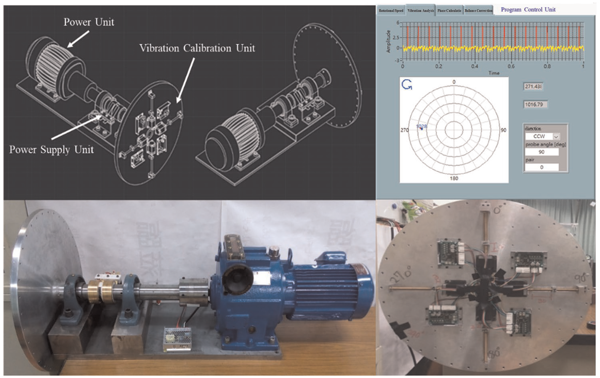
Smart balance correction experimental simulation platform.
Components for smart balance correction experimental simulation platform.
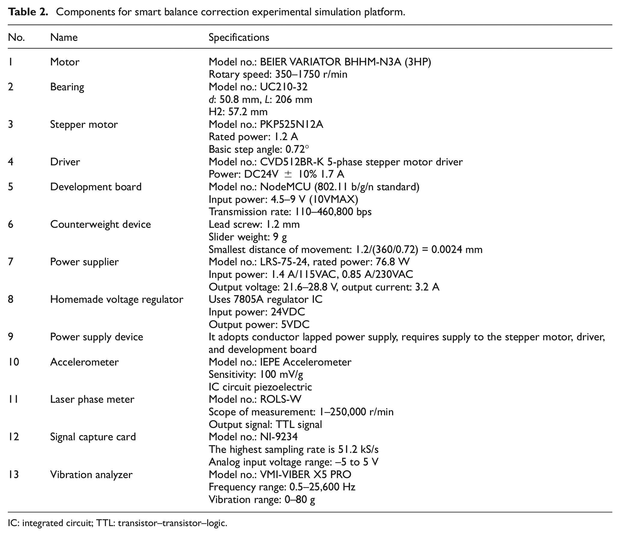
IC: integrated circuit; TTL: transistor–transistor–logic.
Results and discussion
Initial state correction and records
The VMI-VIBER X5 PRO vibration analyzer was used to perform the smart balance correction of the experimental simulation platform, after which the initial vibration analysis results of the experimental simulation platform were recorded. At a speed of 359.968 CPM, the root mean square (RMS) amplitude was 0.455 mm/s, the base frequency was 5.94994 Hz, and the phase angle was 40.324° (as shown in Figure 6(a) and (b)).

(a) Initial angle of phase state correction and records of experimental platform. (b) Initial RMS state correction and records of experimental platform.
Simulation of 4.6 g weight imbalance
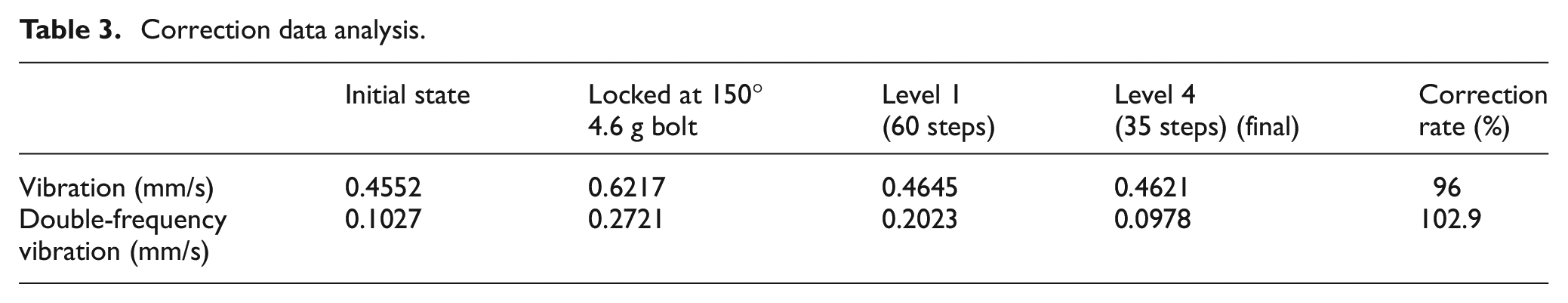
When the system simulated 4.6 g of weight imbalance, it can be seen from the human–machine interface that the RMS amplitude increased from 0.455 to 0.562 mm/s (as shown in Figure 7), and the phase increased from the original 40.324° to 137.962° (as shown in Figure 8). When counterweight #1 was controlled to move 60 steps, the RMS amplitude could be adjusted to 0.464 mm/s, and the phase could be adjusted to 99.481° (as shown in Figure 9). When counterweight #4 was moved 35 steps, the RMS amplitude could be adjusted to 0.462 mm/s, and the phase could be adjusted to 88.72° (as shown in Figure 10). The correction data analysis is shown in Table 3, which indicates a balance correction rate of 96%.
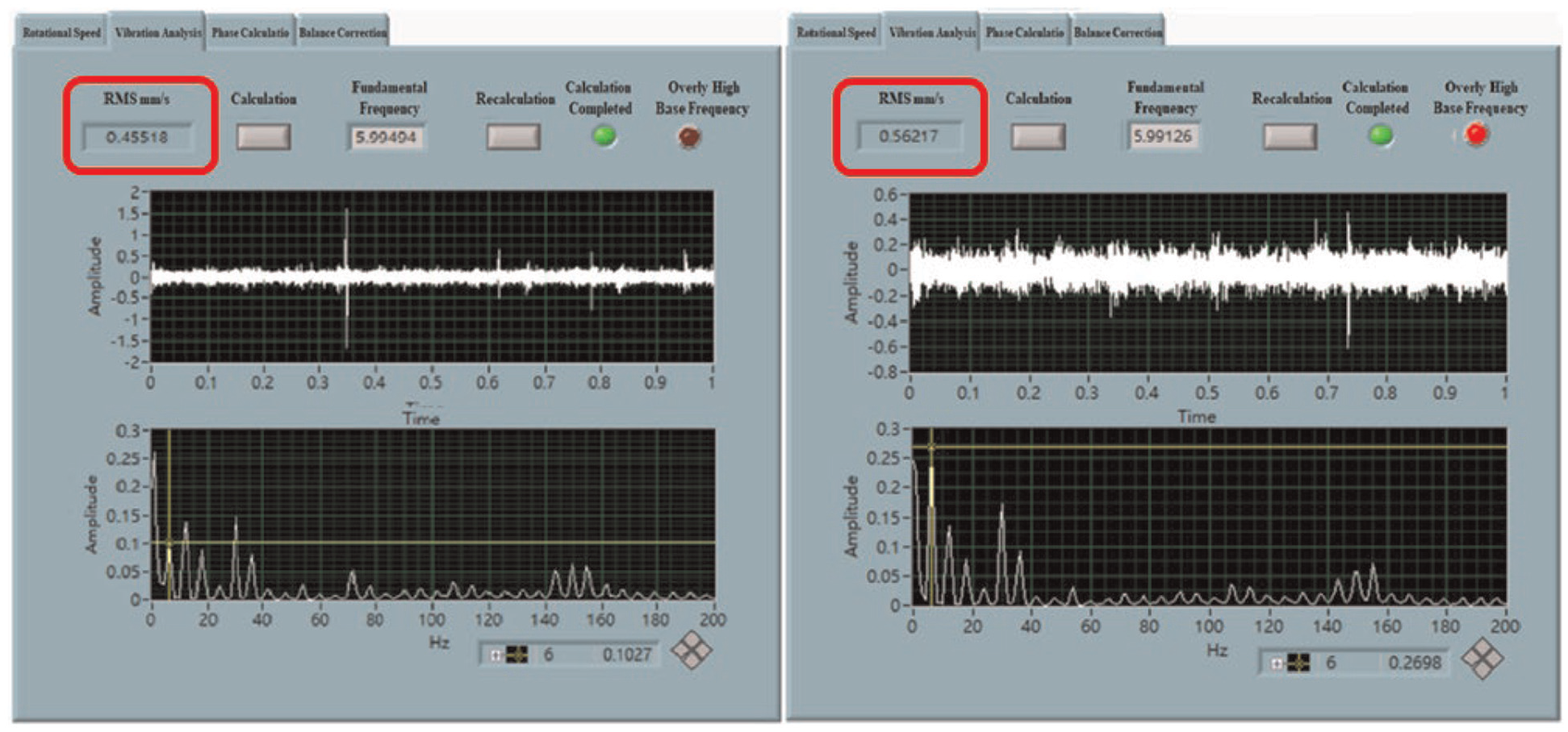
RMS change in 4.6 g weight imbalance on the experimental platform.

Phase change in 4.6 g weight imbalance on the experimental platform.

State of system vibration correction when the counterweight #1 moves 60 steps.

State of system vibration correction when the counterweight #4 moves 35 steps.
Correction data analysis.
Simulation of 3.2 g weight imbalance
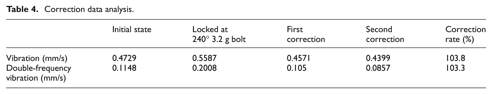
When the system simulated 3.2 g of weight imbalance, it can be seen from the human–machine interface that the RMS amplitude increased from 0.455 to 0.55875 mm/s (as shown in Figure 11). When the system automatically controlled the weight to perform the first balance correction, the RMS amplitude could be adjusted to 0.457 mm/s (as shown in Figure 12). For the purpose of further suppressing the vibration generated by the weight imbalance in the system, the system automatically controlled the weight to perform the second balance correction, and the RMS amplitude could be adjusted to 0.439 mm/s (as shown in Figure 13). The correction data analysis is shown in Table 4, which indicates a balance correction rate of 103.8%.

RMS change in 3.2 g weight imbalance on the experimental platform.
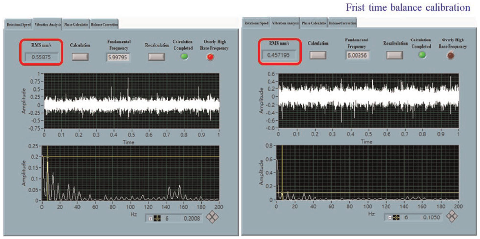
First smart balance correction performed by the system.

Second smart balance correction performed by the system.
Correction data analysis.
Conclusion
In this study, analysis and experiments related to rotary machine vibration monitoring and balance correction were conducted. By constructing a physical simulation platform, and using LabVIEW and Arduino IDE to complete the control program and the human–machine monitoring interface, an initial experiment on vibration monitoring and automatic balance correction was conducted, the feasibility of the experiment was verified, and the following conclusions were drawn.
VMI-VIBER X5 PRO was compared and verified against each other. The measurement results showed that the amplitude error values of the two measurement systems were about 1.3%, and the phase error value was about 0.1%. The error value of the rotary speed was about 0.4%, and the accuracy of the measurement system was confirmed through experiments.
On the experimental simulation platform, continuous online active balance correction experiments were conducted. After 5 min of online correction, the amplitude correction rate was 96%, and the double-frequency correction rate was 102.9%. Although there was still some residual vibration in the amplitude, not only was that in the double-frequency part completely corrected, but even the original residual imbalance in the original body was also corrected. The experiments thus proved the feasibility of the system in performing continuous online balance correction.
On the experimental simulation platform, continuous automatic balance correction experiments were also conducted. After 3 min of automatic correction, the amplitude correction rate was 103.8%, and the double-frequency correction rate was 103.3%. Excellent performance was achieved with respect to both the amplitude and double-frequency correction rates. The state of balance of the rotor was better than the initial state of the system after the balance correction was performed. The feasibility of the system in continuous online automatic balance correction was thus also verified.
The three major novel aspects of the idea included in this study are as follows:
1. Automatic balance correction increases the reliability of rotating equipment
When rotating equipment produces imbalance vibrations, the calculations performed by the system’s programs can be used to drive the counter-balances, thus achieving rapid correction while the equipment is still operating. In so doing, the system is able to stop the spread of the impacts of imbalance in a timely manner, thereby ensuring the stable effectiveness and safe operation of the equipment as well as preventing abrupt malfunctions.
2. Users can easily understand the vibration signals of rotating equipment
In this study, a control program and a human–machine monitoring interface was developed through LabVIEW and Arduino IDE, so as to control the four sets of counterweights of a stepper motor for the automatic balance correction of rotating equipment. Using the human–machine interface, users can know the locations of the four sets of counterweights as well as the status of the equipment.
3. Collection and recording of abnormal spectrum data
The control program and a human–machine monitoring interface developed through LabVIEW and Arduino IDE offers an uninterrupted monitoring system that records the operating status of the equipment. When the counter-balances start to perform balance correction, the system will automatically record the abnormal vibration spectrum signals that are generated at the time, which serves as a reference for forecasting equipment repairs. This greatly reduces the time of fault detection and identification as well as maintenance costs.
Footnotes
Handling Editor: James Baldwin
Declaration of conflicting interests
The author(s) declared no potential conflicts of interest with respect to the research, authorship, and/or publication of this article.
Funding
The author(s) received no financial support for the research, authorship, and/or publication of this article.