
Abstract
For different operating conditions of an internal combustion engine, the piston–ring–liner compartment represents one of the largest sources of friction and power losses. The aim of this article is to evaluate the effect of the compression ring profile on the main tribological performance of the lubricant in a four-stroke diesel engine. A one-dimensional analysis was developed for the hydrodynamic lubrication between the compression piston ring and the cylinder wall. A numerical method was applied to analyze the influence of different ring geometrical designs during the working cycle on oil film thickness, frictional force, and power losses. Our predicted results were validated with the Takiguchi data of a previous study, and they have shown a good agreement. The results in the current analysis demonstrated that the ring geometry profile, the engine speed, and load have a remarkable effect on oil film thickness, friction force, and friction power losses between the top ring and cylinder liner. Therefore, it would help in reducing friction as well as making a contribution to the improvement of engine performance such as torque, efficiency, and fuel consumption.
Keywords
Introduction
The optimization of the piston rings as important components of combustion engines can contribute to the engine friction reduction since about 20%–40% of the friction losses of the engine are due to the piston ring assembly. The main functions of the piston rings are the sealing between the combustion chamber and the engine crankcase, the support for the heat transfer from the piston to the cylinder wall, and the control of the engine oil consumption. During the compression and working strokes, the compression ring seals the combustion gases and prevents blow-by.
Many researchers have tried to understand the mechanism of piston ring motion through numerical and experimental investigations. Radakovic and Khonsari 1 presented the governing equations and the appropriate numerical solution method to treat thermohydrodynamic problems implying thin-film flows in the presence of transversal compression and shear thinning. They also analyzed thermal and shear effects of oil film on ring performance. Takiguchi et al. 2 studied the variation of the oil film thickness of the top and second piston ring of a truck diesel engine during a cycle using clearance capacitive sensors in the sliding surfaces of the rings. For the investigation of tribological characteristics, Chaudhari and Sutaria 3 compared the results obtained by numerical modeling of the frictional force of the various friction sources with the experimental results. Srinadh and Rajasekhara 4 designed three piston rings with different profiles for a diesel engine using Pro/Engineer software and analyzed the stresses and displacements of the piston and piston rings. The model used was the same for each mechanism, but with different procedures and assumptions. However, they did not specify the steps in the simulation. Mohamed et al. 5 examined the tribological behavior of the piston ring assembly using nanoparticles as nano-lubricant additives, and it showed a decrease in the friction coefficient, power losses, and wear. Turnbull et al. 6 used comparative studies of three compression ring models with increasing levels of complexity such as ring rigid-body dynamics, flexible ring dynamics, and flexible ring model encapsulating gas blow-by. It is shown that power losses due to gas leakage can be as much as six times larger than frictional losses, which are usually considered as the main sources of inefficiency. Tian 7 simulated the force between the rings and their grooves by assuming certain roughness and oil distribution on the rings and grooves in a spark-ignition engine. It was found that if the oil control ring is not able to conform well to the bore, it will lead to increased oil consumption. Mohamed et al. 8 studied the effect of piston ring dynamics on basic tribological parameters that affect the performance of internal combustion engines using dynamics analysis software (AVL Excite Designer). It demonstrated that engine speed and oil viscosity had a remarkable effect on oil film thickness and hydrodynamic friction between the rings and cylinder liner. Baker et al. 9 studied the influence of in-plane dynamics of thin compression rings on friction in internal combustion engines. The results show that the contact transit time is shorter than that required for the ring to reach a steady-state condition. Rahmani et al. 10 used the measured bores and ring profiles to predict conjunctional power loss and percentage fuel energy consumed, and it was found that the effect of bore out-of-roundness can be even more significant than the surface topography. Styles et al. 11 developed a numerical simulation model of the top compression ring to cylinder liner is based on a mixed-hydrodynamic regime of lubrication to study the effect of wear of ring coating upon friction and sealing performance of the top compression ring. Soderfjall et al. 12 used a numerical simulation model for prediction of the tribological effects of an oil control ring running against an out-of-round cylinder liner in a heavy-duty diesel engine. It showed that the friction for the oil control ring at mid-stroke to be 78% larger in an out-of-round cylinder liner compared to a perfectly cylindrical one. Zhang et al. 13 proposed a design approach for optimizing the piston ring profiles by considering mixed lubrication, it was found that the minimization of friction and maximization of oil film load-carrying capacity can be balanced simultaneously when the degree of the polynomial is 2 and 5. Morris et al. 14 showed that temperature rise due to inlet shear heating of the lubricant by convected heat into the bulk lubricant flow is considerably more important than a modest rise through lubricant viscous shear in the contact because of short transit time at any instant of time. The friction reduction can be achieved by reducing the tangential force on the oil control ring. The results have shown that the ring will conform well to a cylinder liner with lower order out-of-roundness.
In this article, our main purpose is to study the effect of the engine speed and load on the piston friction characteristics and also to find the best compression ring profile type which presents a minimum of effect on the main tribological performances such as the friction force and frictional power loss to maximize the torque and power of diesel engine.
Modeling assumptions of piston–ring–liner
The in-cylinder pressure which is one of the inputs for the simulated engine code was modulated using the first law of thermodynamics. 15 For the simulation model, we take into account the following assumptions 16 :
The friction between the rings and the liner includes the lubricant shear friction given by the Reynolds equation and the friction due to the Greenwood–Tripp asperity contact. 17
In the piston ring modeling, we have the moments and forces for each ring. The hydrodynamic pressure distribution between the running surface of the ring and the liner is determined by solving the Reynolds equation in each time step.
The volumes are connected due to the actual clearances of ring end gaps and the actual position of the rings in the grooves. The gas flow behind the rings and between ring and groove flanks is considered.
The oil film is taken into account between the ring running surface and liner by calculating the pressure distribution in the clearance. 18
It was assumed that the ring contracts and extends uniformly around the circumference, and that the ring sits on a single point with a running contact on the top or bottom of the groove. The contact points also seal the pressure on one side from the other, so that there is a gradual change in pressure at this contact point.
The lubrication regime in the cylinder is influenced by the variation in piston speed, which affects the friction between the piston ring and the liner throughout the piston stroke. In this study, we consider hydrodynamic lubrication, which means that the ring always moves over a complete fluid film.
The frictional force reaches its maximum where the piston speed is highest, that is, the piston position is at mid-stroke. If the engine speed or oil viscosity is high, a thick oil film is formed which is not completely ejected even at dead centers where the piston speed is zero. 19
Governing equations for piston ring friction and lubrication
Kinematic relationships of connecting rod and crank mechanism
Due to the high inertia of the connecting rod–crank system, the position of the piston will not be affected by the piston ring action. The axial position

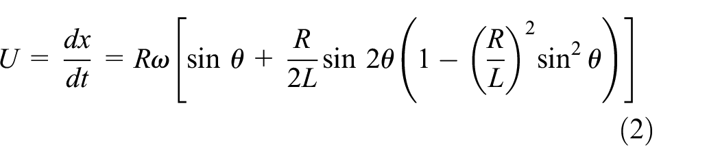
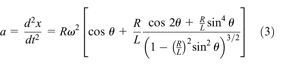
where
Reynolds equation
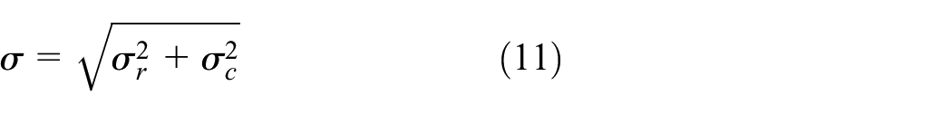
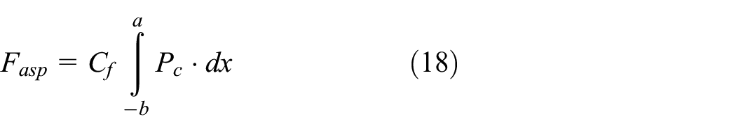
In the case of hydrodynamic lubrication, the oil fully supports the load of the ring on the liner, and therefore, the frictional force generated by the segment–liner interaction depends on the lubricant properties, the height, and width of the film below the ring surface. To determine the frictional force, coupled equations governing the fluid mechanics of the lubricant and the forces acting on the segment have to be solved. Figure 1 shows the schematic of the studied system. In the general case, the unknowns are the minimum oil film thickness
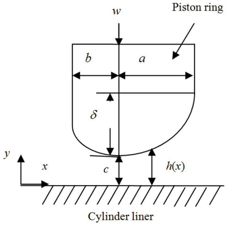
Hydrodynamic lubrication between the ring and the liner.
The Reynolds equation establishes the relationship between the height, width, and the oil film thickness between ring and liner and the oil pressure gradient. In this study, a two-dimensional approach is used in which the ring and liner lubrication parameters are determined as a function of piston position, and the Reynolds equation is thus reduced to a one-dimensional form. Under these conditions, the Reynolds equation is written as follows21,22

where
Taking into account the symmetry of the axes along the cylinder axis, equation (4) becomes 15

The variation of the film thickness under the ring with respect to position and time is 16

where
The surface shear stress of lubricant between two parallel plates is given by the following relationship

Governing equations of piston ring dynamics and gas flow
Figure 2 shows the model of piston ring dynamics considers forces and moments due to inertia, friction, and the flow of the gas from the combustion chamber through the inter-ring volumes into the sump.

Applied forces in the ring system.
Ring axial and radial dynamics
Axial motion of the piston ring
The main forces acting in the axial direction of the ring cross-section are given by the following equation describing the mechanical equilibrium of forces 5
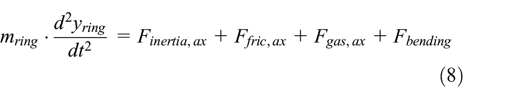
where
If
Radial motion of the piston ring
Piston rings can move radially into the groove; this motion is necessary to account for thermal expansion of the ring, but also to comply with the piston secondary motion and liner distortion. This motion gives the so-called conformability to the cylinder bore, that is, the capacity to adapt to the bore surface. The contact forces between the cylinder liner and piston ring running surface are calculated as 5

where
If
The asperity contact pressure can be calculated using the model of Greenwood and Tripp 17

where
where
The composite Young’s modulus is calculated as 23

where
The Gaussian distribution of asperity heights on the surface is expressed as
In this article, the following simplified expression is used 21

with
Hydrodynamic and asperity contact model
The total frictional force includes both viscous and asperity contributions. The viscous frictional force is caused by the viscosity of the lubricant. The lubricant is a Newtonian fluid, so the frictional force is expressed as

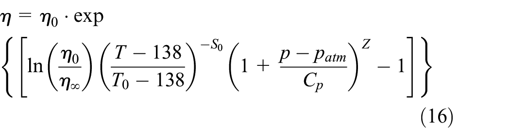
where the oil viscosity
where

where
The asperity frictional force is caused by contact between the ring surface and cylinder wall 25
where
The total frictional force is therefore expressed as

The coefficient of friction defines the lubrication regime and friction characteristics. It is calculated as 25

where
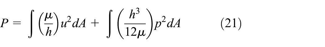
The frictional power loss is calculated as
Gas flow model
The gas flow dynamics is modeled using the ideal gas equation and the continuity law, as described in the following equation for a single inter-ring volume26,27

Simulation algorithm
The numerical simulation in this article is computed using the GT-Suite simulation software, as illustrated in Figure 3. The simulation algorithm is established by considering variable piston velocity, gas pressure, and lubrication conditions, as well as variable lubricant viscosity. The Reynolds equation (5) is solved using the finite difference method and the application of the above approximations with boundary conditions. Relaxation method is used for finalizing the numerical solution using an initial guess for film thickness equation (6). The Newtonian lubricant is used in the numerical scheme for the lubrication solution. The average Reynolds equation is solved to calculate the distribution of hydrodynamic pressures. The gradients of pressure depend on the film thicknesses. Gauss–Seidel iterative numerical scheme is used to solve the Reynolds and the oil film thickness equations simultaneously and show maximum and minimum film thicknesses and pressure fields.
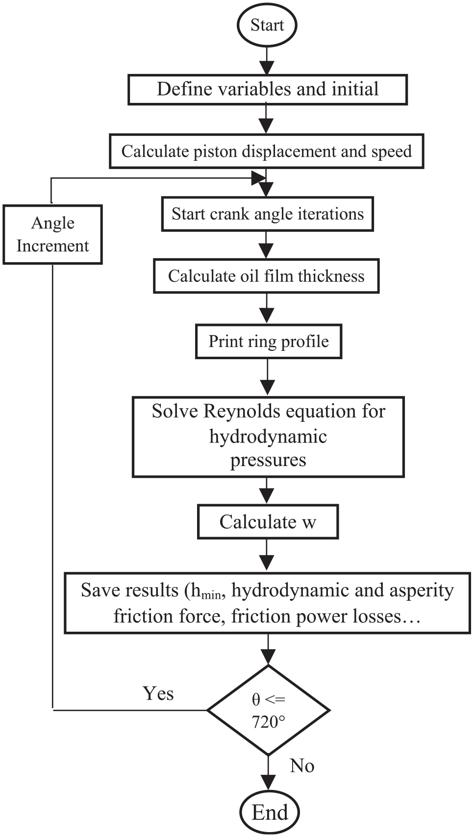
The flow diagram of the simulation procedure.
The compression ring profile plays an important role in the entertainment of the lubricant between the top piston and cylinder liner. Figure 4 and Table 1 show the different top ring profiles and its properties used in this study. The cylindrical shape of the ring provides better hydrodynamic lubrication conditions and the axially shorter contact surface to the liner surface improves sealing. In addition, the negative effects of cylinder deformations during engine operation can be better compensated. Piston rings of this profile type are actually used as compression rings.

Investigated compression ring profiles.
Compression ring profile property.

Results and discussion
Table 2 presents the data used in this investigation. The determination of tribological performance was carried out under a full load of a diesel engine and at an engine speed of 2000 r/min.
Engine data.

The speed piston can be determined by deriving the equation that calculates the distance between the piston and TDC. Figure 5 shows the variation of piston position and speed as a function of crankshaft angle at 2000 r/min for a diesel engine. Piston ring lift is due to piston acceleration, which is the derivative of the piston speed equation (Figure 6).
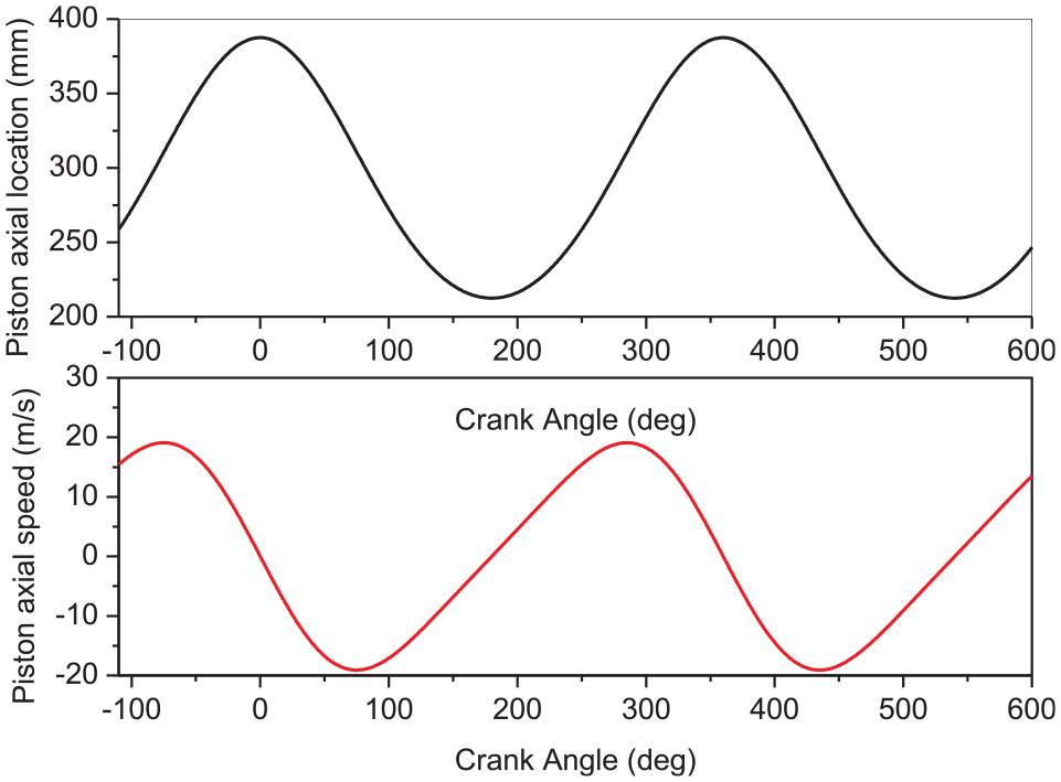
Piston position and speed versus crank angle.

Piston acceleration versus crank angle at 2000 r/min.
Effect of top ring geometry profile
Figure 7 shows the variation of hydrodynamic power losses versus crank angle for different compression ring profiles at full load and engine speed of 2000 r/min. During the operating cycle of the engine, the maximum power losses for all three ring variants are all reached mid-stroke of the piston and then cancel each other out at TDC and TDC, corresponding to the piston velocity variation (Figure 5). The oil film thickness and the hydrodynamic shear increase also at mid-stroke.
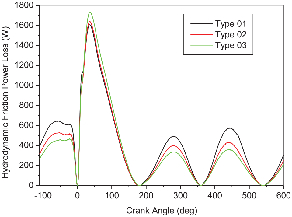
Effect of compression ring profile on hydrodynamic power losses versus crank angle.
Figure 8 presents the variation in asperity friction power loss during a full-load engine cycle at 2000 r/min. The maximum values are in the expansion phase and minimum values in the other phases of the engine cycle. It can be attributed to the fact that there is an increase in asperity contact near the TDC and bottom dead center (BDC) due to the mixed lubrication regime, whereas hydrodynamic lubrication exists for the most part of the stroke. Type 3 of ring design presents higher values.

Variation in asperity friction power loss during a full-load engine cycle at 2000 r/min.
Figure 9 shows the variation of hydrodynamic friction force versus crank angle for different ring profiles. That maximum friction value is at point of maximum cylinder pressure. The negative part of the curve is due to the change of piston speed direction through the reciprocating motion. It has been observed that the highest friction force value occurred during the expansion stroke (from −110° to 180°) with a peak of 235 N, it mainly occurs near the TDC of combustion, and the value of the friction force is obviously higher than that of the other moments. Type 1 ring profile has maximum friction force and type 3 ring profile has minimum friction force. At TDC, the film thickness for type 3 ring profile is found to be lowest. It is expected that the friction due to lubricant viscosity was minimum.

Hydrodynamic friction force for different ring profiles at 2000 r/min.
In general, the maximum asperity frictional force is reached at TDC and BDC during the operating cycle, due to the low critical speed and, consequently, the low oil flow at these points. Figure 10 shows the asperity frictional force between the upper ring and the cylinder liner as a function of the crankshaft angle for different ring profiles at an engine speed of 2000 r/min and full load. Type 1 has the lowest asperity friction force, followed by type 2 and the highest force with type 3 especially at TDC after the compression stroke.

Effect of top ring profile on asperity friction forces at 2000 r/min.
Figure 11 shows the variation of the maximum contact oil pressure as a function of the crank angle for different ring profiles. The maximum value of the hydrodynamic oil pressure is reached near the TDC. Type 3 ring profile has the maximum oil pressure, followed by type 2 and type 3 ring profiles with the minimum oil pressure.
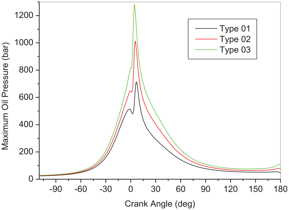
Effect of top ring profile on the maximum oil pressure versus crank angle for near TDC at 2000 r/min.
Figure 12 shows the variation in film thickness for different types of ring profile. In order to validate the film thickness values obtained through simulation, data collected from the literature were utilized. Takiguchi et al. 2 conducted experiments on a four-stroke engine and found the film thickness. The same engine parameters were used as input for the GT-Suite software to find the oil film thickness. Since some data were not available, few assumptions were made as inputs of the program, like the ring radial width which was assumed to be 0.3 times the bore, ring material properties where the ring density was 7900 kg/m3, and modulus of elasticity was taken to be 205 GPa. The output of the simulation code is almost matching with the work done by Takiguchi et al. 2 The small variations could be due to the assumptions that were made for the input. The film thickness is maximum at the mid-point of the different cycle phases. In the expansion stroke, the oil film thickness is lower. At the dead centers, the film is very thin, especially at the BDC after the expansion stroke and at the TDC at the beginning of the intake stroke, which can lead to high wear of the cylinder wall due to contact between the surfaces. It can be observed that type 1 ring face profile provides a thicker film than the other two variants.
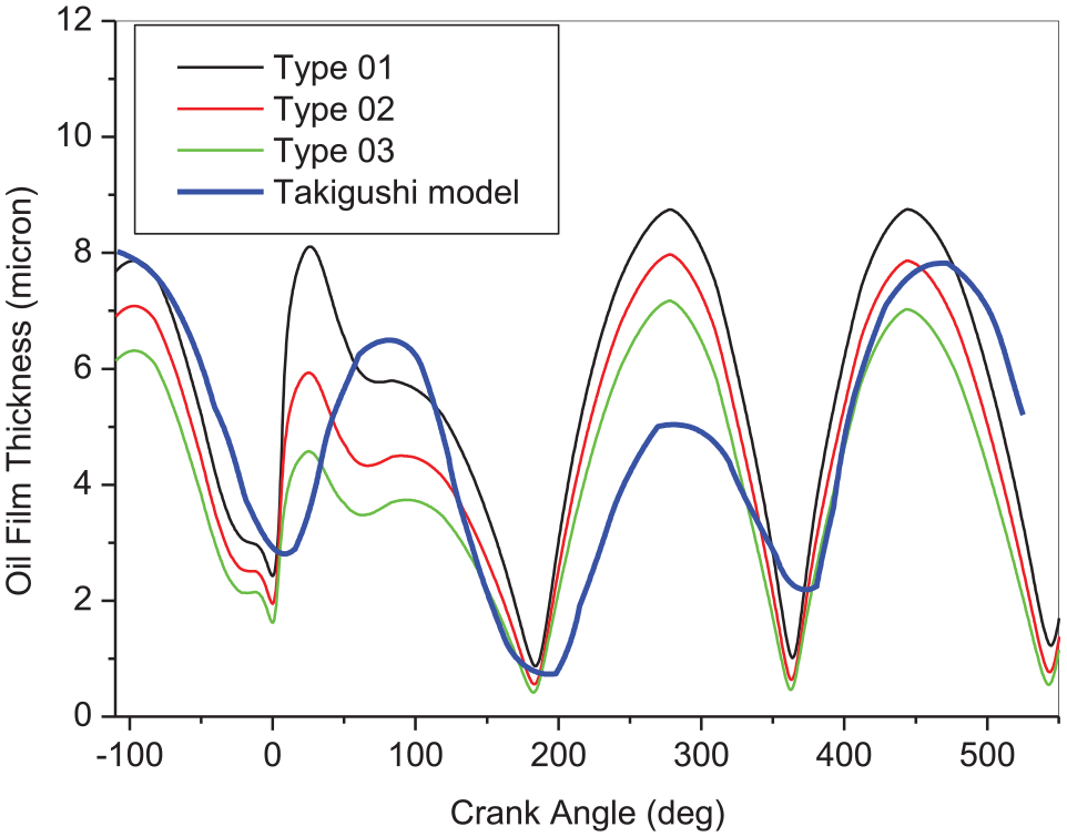
Minimum oil film thickness for different ring profiles during engine cycle for 2000 r/min and Takiguchi model. 2
Figure 13 shows the variation in shear rate as a function of crank angle for different compression ring profiles. The maximum shear rates vary over the cycle from 1.5 × 10⁻⁶ to 3.0 × 10⁻⁶ s−1. Type 1 has a higher effective oil film shear rate, followed by type 2 and the lowest with type 3.

Oil film effective shear rate for different ring profiles during engine cycle.
Figure 14 shows the variation of friction tension as a function of crank angle for different compression ring profiles. In the combustion and expansion period, there is a noticeable change in the frictional tension. The variant of type 1 has higher frictional tensions than the other variants.

Friction tension with respect of crank angle for different compression ring profiles.
The simulated result for ring twist angle is shown in Figure 15. The negative values of the twist angle refer to the ring’s back (inner diameter) moving down and the ring’s face moving up. The highest twist will take place just after TDC following compression since it is necessary to generate the lift force as the piston speed is low at the TDC. It can be seen that type 3 has the largest ring twist angle and type 1 has the smallest ring twist angle.

Ring twist angle versus crank angle for different ring profiles.
Effect of engine speed
Figure 16(a)–(c) demonstrates the effect of engine speed on the friction characteristics (friction force, friction power loss, and minimum film thickness) between piston rings and cylinder liner with SAE 20W40 engine oil and at full load. From Figure 16(a), the friction force reached its peak at TDC during the start of the expansion stroke for the tree engine speed due to increased asperity (boundary) friction force with a decrease in sliding speed at this location. The results showed that friction force increased with increasing engine speed as a result of increasing oil film thickness between piston rings and cylinder liner. This increase was strongly observed at 2000 r/min.

(a) Variation of the friction force, (b) friction power loss, and (c) minimum film thickness versus crank angle for different engine speeds.
From Figure 16(b), the power losses were observed to reach its peak at mid-stroke where the reciprocating speed reached its maximum and hence, the oil film thickness and the hydrodynamic shear being at its minimum at TDC and BDC locations where the speed and oil film thickness are critically low. Moreover, the power losses increase with increasing the sliding speed. This behavior might be attributed to the increase in hydrodynamic shear strength resulting from the increase in the oil film thickness.
From Figure 16(c), the oil film thickness reached its maximum value in the middle of the stroke where there is hydrodynamic lubrication, while the minimum oil film thicknesses tend to be lower at TDC and BDC. These are likely to be the points where the piston ring undergoes metallic contact with the cylinder liner (boundary lubrication). In general, the oil film thickness increased with an increase in engine speed (reciprocating sliding speed).
Effect of engine load
Figure 17(a)–(c) shows the simulated results for the friction characteristics of the piston’s top compression ring. Figure 17(c) shows that the minimum oil film thickness is nearly zero at TDC following the compression stroke due to the increase in cylinder pressure with the increasing load, which reduced the thickness of the oil film. In addition, the minimum oil film thickness increases with engine load. The friction force by direct asperity contact increased suddenly due to cylinder pressure at TDC. The friction force similarly increased with engine load (Figure 17(a)). From Figure 17(b), the power loss of the first compression ring had a peak near the middle of each stroke. This is because the piston sliding velocity has a large influence on the friction power loss calculation. Although the piston sliding velocity is very low, there was a peak power loss near TDC due to a very large friction force in the expansion stroke. Analogously, the first compression ring power loss increases with engine load at the compression stroke.
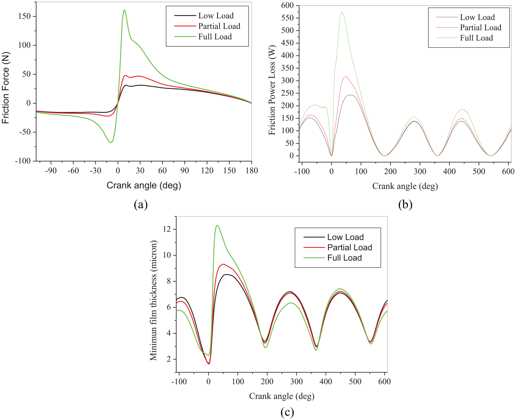
(a) Variation of the friction force, (b) friction power loss, and (c) minimum film thickness versus crank angle for different engine load.
A significant factor influencing the oil consumption of the liner/ring system is the deformation of the cylinder. A cylinder bore may appear perfectly round, but when examined more closely at the micrometer level, it can be strongly deformed. Pressure and combustion temperature gradients during engine operation can cause additional deformation. In fact, bore distortion in internal combustion engines is difficult to prevent. Figure 18 gives an illustration of a deformed cylinder bore. In the radial direction, there is a high deformation especially in the upper part of the cylinder which is subject to high thermal stress. The deformation of the bore affects the capability of the piston rings to maintain contact with the cylinder liner.

Three-dimensional view of cylinder bore distortion.
Figure 19 presents the friction coefficient variation versus ring profile type for engine speed of 1000 and 2000 r/min. The friction coefficient was found minimum for type 3 ring and maximum for type 1 ring. The reason for minimum friction coefficient for type 3 ring was due to the minimum force acting between the ring and the cylinder liner. The total force can be reduced using tribopads inserted into the piston and tribo-inserts inserted into the cylinder liner. 16

Friction coefficient versus ring type and engine speed.
Conclusion
The theoretical results obtained with the numerical model developed to prove that the engine speed, load, and profile of the compression rings have an important effect on the tribological behavior of the system piston ring–cylinder liner. The modification of the compression ring profile contributes to the reduction of frictional power losses and thus to the improvement of the tribological performance of the internal combustion engine. The increase in asperity contact causing low oil films at TDC and BDC as well as friction asperity power losses can be observed. At mid-stroke of the piston motion, thicker oil films were observed despite the presence of higher hydrodynamic frictional forces and lower oil viscosity. There was a good agreement between the results obtained with the developed numerical model and those of the Takiguchi model. In this study, the following results could be deduced:
The lowest frictional force is for type 3 ring profile, which results in a reduction in engine friction losses and an increase in lubricant and fuel economy.
The minimum oil film thickness for type 3 compression ring profile does not necessarily mean a higher frictional force and shear stress. Despite a minimum oil film thickness, the wear rate is not affected.
The increase in engine speed (from 1000 to 2000 r/min) and engine load (low to full load) increases the friction force, friction power loss, and minimum film thickness.
Despite a large number of phenomena have been already taken into account, many other ones which could significantly affect tribological performance have been omitted. In the future, these authors plan to take into account the occurrence of Bore distortion orders to investigate the sealing capacity of the ring-pack in terms of ring dynamics, inter-ring pressures, and mass flows.
Footnotes
Handling Editor: James Baldwin
Declaration of conflicting interests
The author(s) declared no potential conflicts of interest with respect to the research, authorship, and/or publication of this article.
Funding
The author(s) received no financial support for the research, authorship, and/or publication of this article.