
Abstract
Lubricant leakage will inevitably occur during the working process of wellbore trajectory control tools. Even including the lubricant compensation system, serious leakage will still cause lacks lubrication of the internal mechanical structure as well as electronic system damaged by external infiltration fluid, especially when it comes to battery sub and other electronic equipment. Seal system leakage prediction method was presented based on the assumption of steady gap flow. It is assumed that there is a constant gap between the lip seal and the rotating shaft, the gap height is determined by oil film thickness, and the length of the gap was determined by the contact analysis using the Mooney–Rivlin constitutive model. The analysis results show that the contact length between the primary seal lip and the rotary shaft is about 0.1 mm under the condition of ensuring the contact between the deputy seal lip and the rotary shaft. The overall lubricant leakage finite element analysis model was established, and the relationship between the internal lubricant pressure of the tool and the total leakage was obtained. The results of analysis indicate that under the internal pressure of 0.03 MPa, the lubricant leakage is approximately 6 mL/h, which was verified by experiments.
Introduction
The wellbore trajectory control tool is a directional rotary steering drilling tool that goes down with the drill bit during work. It can automatically and flexibly change the direction of the drill bit when drilling complex structure wells such as directional wells and horizontal wells.1,2 Due to the harsh and complex underground environment, the wellbore trajectory control tool often loses its original functions by oil leakage. This makes sealing a key technology to improve tool life. Failure of the seal system will significantly affect the operation of the mechanical system, thereby affecting the accuracy of the bit guidance. If the leakage is serious, it will have a fatal impact on the electronic equipment such as the measurement and control system and battery sub, which will cause the tool to lose its function. In order to prevent the internal and external pressure imbalance of the tool due to lubricant leakage, the tool’s upper dynamic seal is designed with a lubricant compensation and pressure balancing system. However, the volume of lubricating oil that can be compensated by the lubricating oil compensation system is limited. When the amount of lubricating oil leakage exceeds the volume that the system can compensate, it will cause an unbalanced pressure inside and outside the tool, and the drilling fluid will penetrate the seals, contaminate the internal environment.3–5 Therefore, it is necessary to analyze the sealing performance of the wellbore trajectory control tool, calculate the amount of lubricating oil leakage, determine the continues working time of the tool, and to guide the lubricant replenished.
Working principle of seal system
Basic structure of dynamic seal for wellbore trajectory control tool
The total length of the wellbore trajectory control tool is about 2.7 m. Offset mechanism, bearing, and other components were installed in the annular space between tool mandrel and jacket. The left and right ends are sealed with different sealing device, and the sealed cavity is filled with lubricating oil. The left end dynamic seal is mainly composed of a rotary shaft lip seal and an internal lubricant compensation and pressure balancing system, 6 as shown in Figure 1. To balance the internal and external pressures, the seal contains a flexible seal combination structure, as shown in Figure 2. The sealing cavity of the left and right dynamic seal structure is connected. The built-in lubricant compensation and pressure balancing system of the left dynamic seal can balance and compensate for the loss of internal lubricating oil within a wide range of 1670.87 mL. The flexible seals used by the lower dynamic seal can effectively reduce shock and vibration and balance internal and external pressure in a small range.
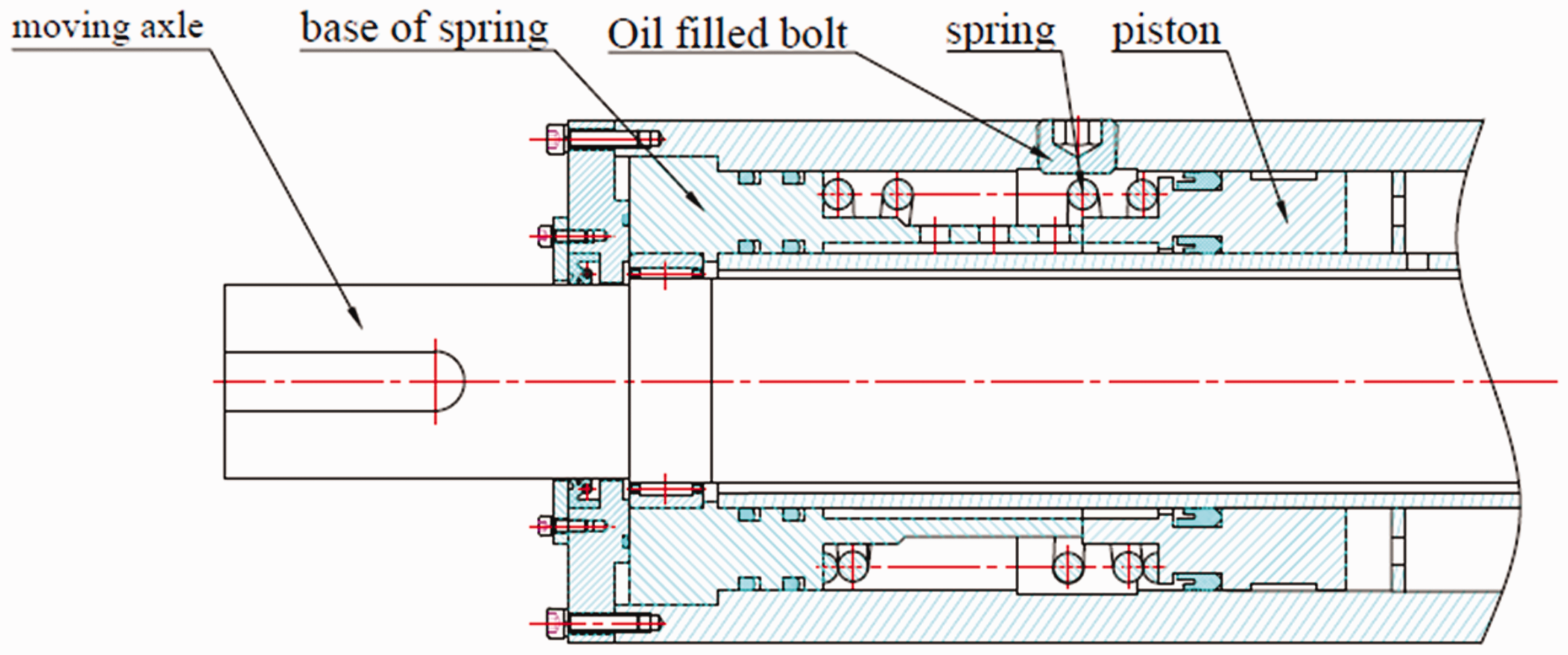
Left dynamic seal.

Right dynamic seal.
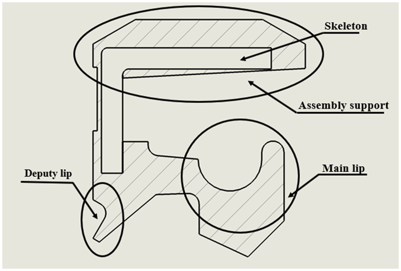
The sealing ring used by the wellbore trajectory control tool is based on the standard GB/T9887-2008, which is mainly composed of assembly support, skeleton, spring, main lip, and deputy lip, 7 as shown in Figure 3.
Rotary shaft lip seal.
This type of rotating shaft lip seal is made of nitrile rubber, and its sealing method adopts an outer diameter static seal and an inner diameter dynamic seal. The outer ring of the rotary shaft lip seal is in contact with the seal housing and uses an interference fit to achieve a sealing effect. When the sealing lip is in contact with the rotating shaft, an oil film is formed on the air side and the oil side to prevent oil leakage.
The back-chamfer design of the outer ring helps release the backward thrust during the installation and plays a guiding role at the same time. A support frame is installed inside the seal ring, which effectively enhances the rigidity of the outer diameter of the oil seal. The deputy lip can effectively prevent external impurities (such as dust, mud, and water) from entering the contact area.
Hydrodynamic lubrication model of rotary shaft lip seal
The hydrodynamic lubrication between the elastic deformational surface of sealing lip and rotation shaft generate pressure–viscosity effect of the lubricating liquid, which has a significant effect on the thickness and pressure distribution of the lubrication film, is called elastohydrodynamic lubrication.8,9 In elastohydrodynamic lubrication, not only include the film flow but also contain the elastic deformation of the contact body. The theory of elastohydrodynamic lubrication reflects the interrelationships among the material properties, shape, lubricant viscosity, load, and lubricant thickness of elastomers. However, the lubricant film thickness is very important, which directly affects the sealing effect. Grubin’s formula is used to calculate the oil film thickness under line contact. The formula is as follows

In the formula, h is the minimum oil film thickness (m);
Through the above formula, substituting the actual parameters, the thickness of the oil film can be obtained.
Calculation model of steady gap leakage
Because the sealing structure of the wellbore trajectory control tool is very complicated, some assumptions need to be made in order to analyze the leakage as follows:
10
The tool works under the design condition (Temperature <150°C, build-up rate <8°/30 m). The lubricant oil inside the tool does not leak through the relatively static joints such as static seals and threads. Vibration impact and other conditions will not affect the oil leakage. Regardless of the pumping effect of the lip seal of the rotating shaft, only the steady gap leakage of the lip contact surface is considered.
Under the above-mentioned assumptions, the leakage of the wellbore trajectory control tool can be regarded as the differential pressure flow of the lubricant in the concentric annular gap. The flow calculation formula of the concentric annular gap is

In formula (2), Q is the lubricating oil flow rate (
Considering the cross-sectional shape of the lip seal, let the contact width of the sealing lip and the rotary shaft be L and the contact load be P. As shown in Figure 4, the formula for calculating the leakage of the tool sealing lip is
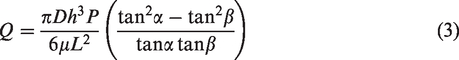
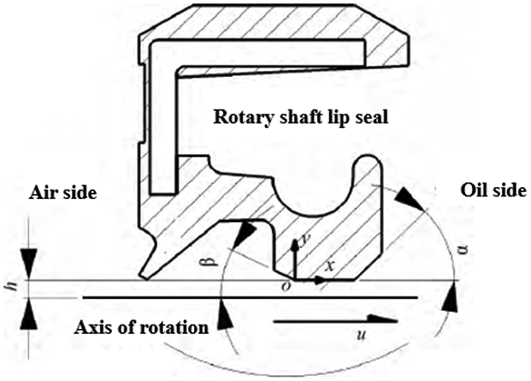
Lip seal contact region.
In formula (2), P is the contact load between the sealing lip and the rotating shaft (N); α is the lip angle on the oil side of the sealing lip (°); and β is the lip angle on the air side of the sealing lip (°).
Rotary shaft lip seal contact analysis
Rotary shaft lip seals are non-contact dynamic seals. The main working principle is to use flexible materials to block the fluid flow to prevent leakage. If the pressure force is too large, the contact surface will be squeezed, causing excessive frictional resistance, preventing relative movement, and causing wear of the seals, reduced service life of the dynamic seal.11,12
In order to get the length of constant gap between the lip seal and the rotating shaft, the contact between the flexible seal lip and the rotating shaft must be analyzed. To ensure that the seal lip is in contact with the rotary shaft, the rotary shaft diameter should be slightly larger than the minimum seal lip diameter. It is necessary to establish a contact analysis model of the seal and the rotary shaft, and analyze the relationship between the contact length and the compression of the seal lip.
Rotary shaft lip seal is a typical axisymmetric structure. 13 An axisymmetric analysis model was established to control the radial displacement of the rotary shaft to simulate the compression of the seal lip.
Finite element analysis model
Rotary shaft lip seal contact analysis model was established based on GB/T9887-2008 regulations and specific measurement results. Both the sealing ring and the rotating shaft are modeled by axisymmetric. The seal housing and the rotation shaft are modeled as rectangles, and the rotation shaft lip seal is placed according to the assembly position, as shown in Figure 5. In order to understand the deformation of the contact position, the contact area is locally meshed and rest is divided by free triangle mesh. A total of 9826 units are divided, as shown in Figure 6.

Geometric model of dynamic seal.

Dynamic seal model meshing result.
Parameter setting and contact definition
The rotating shaft lip seal uses nitrile rubber, and the stress–strain relationship of rubber materials is very complicated. For one-dimensional or two-dimensional strain, the Mooney–Rivlin model has a high accuracy for the simulation, especially the stretching ratio of rubber range from 0.5 (compression) to 2 (stretching).
The Mooney–Rivlin model assumes that rubber is an isotropic and incompressible superelastomer. The general form of the strain energy density function W of the isotropic Mooney–Rivlin model is
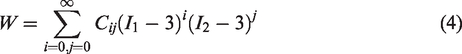
In the formula,
In order to make the simulation simple and easy to calculate, the two-parameter Mooney–Rivlin model was used to analyze the contact analysis model of the rotary shaft lip seal. The strain energy density function of the two-parameter Mooney–Rivlin model is

The mechanical parameters
There are three sets of contact pairs in the model. The first set of contact pairs is used to describe the contact between the sealing lip and the rotating shaft, and the second group is used to describe the contact of the deputy lip with the rotating shaft. The third group is the contact between the supporting skeleton of the seal and the rubber material. Among them, the main lip and deputy lip of the rotary shaft lip seal are the main research objects.
In order to fully simulate the stress and deformation of the rotary shaft lip seal during the assembly process, the different compression amount of the dynamic seal was simulated by setting the preset displacement.
Analysis results of different compression amounts
After the pre-processing of the model is completed, the dynamic seal needs to be analyzed under different compression amounts to obtain the seal deformation, stress distribution, and the stress of the contact part. The analysis results are shown in Figure 7.

Von Mises stress of lip seal in different compression—(a) compression: 0.1 mm; (b) compression: 0.4 mm; (c) compression: 0.7 mm; and (d) compression: 1.0 mm.
With the continuous increase in the compression, the contact stress between the main lip of the sealing lip and the rotary shaft is increasing, and elastic deformation occurs, which gradually increases the contact length between the sealing lip and the rotating shaft. The sealing lip gradually approaches the rotary shaft and finally contact with the rotary shaft when the compression is 0.7 mm. The relationship between the maximum contact stress of the sealing lip and the amount of compression is shown in Figure 8. The result shows that with a compression of 0.7 mm, the maximum contact stress of the sealing lip is 1.2 MPa, and the deputy lip has just come into contact with the rotating shaft. This state is the critical state before the dynamic seal failure; at the same time, the lubricant leakage reaches the maximum.

Max contact stress of the lip seal.
The analysis results show that the rotary shaft lip seal has a compression amount of 0.7 mm or more during use. However, in order to estimate the leakage amount of the seal system, the contact length between the seal lip and the rotating shaft must be taken at this critical state, which is 0.1 mm.
Analysis of lubricant leakage in wellbore trajectory control tool
The dynamic seal structure of the wellbore trajectory control tool is divided into left and right ends. The left end dynamic seal mainly uses a rotary shaft lip seal. There is a gap of 0.5 mm between the oil side and the lip seal. Lubricant mainly leaks to the rotary shaft lip seal through this gap, and then passes the seal. The leakage of the lower dynamic seal is mainly on the annular surface between the outer seal movable ring and the bearing cup. 14 Therefore, when the tool spindle rotates, there is mutual movement between the outer seal moving ring and the bearing cup, and the lubricant stored inside the tool leaks out through this relatively moving surface.
Finite element analysis model and meshing
According to the calculation model of the constant gap leakage amount, it is considered that the lubricant leakage is caused by the steady gap between the lip seal and the rotary shaft. The height of this gap can be obtained by taking the contact analysis results into formula (1), which is only about 1 µm. When establishing the overall leakage model, the gap was set to 1 µm, and the width was set to 0.1 mm. Based on the actual size of the tool, an analysis model as shown in Figure 9 was established. The model meshing as shown in Figure 10.
Overall leakage analysis model.

Overall leakage analysis model meshing result.
Leak analysis results
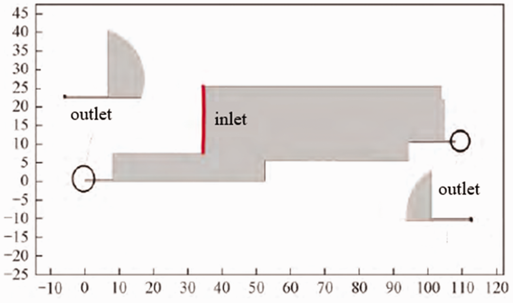
The steady-state solver is used to solve this model. The calculated exit velocity is shown in Figure 11. In order to obtain the flow rate at the outlets, the overall probe is set, and the physical quantity of the probe is set to measure the volume flow rate. Set the inlet and outlet pressures to the variable press, and set the variable range to 0.01–0.05 MPa.
Exit velocity analysis results.
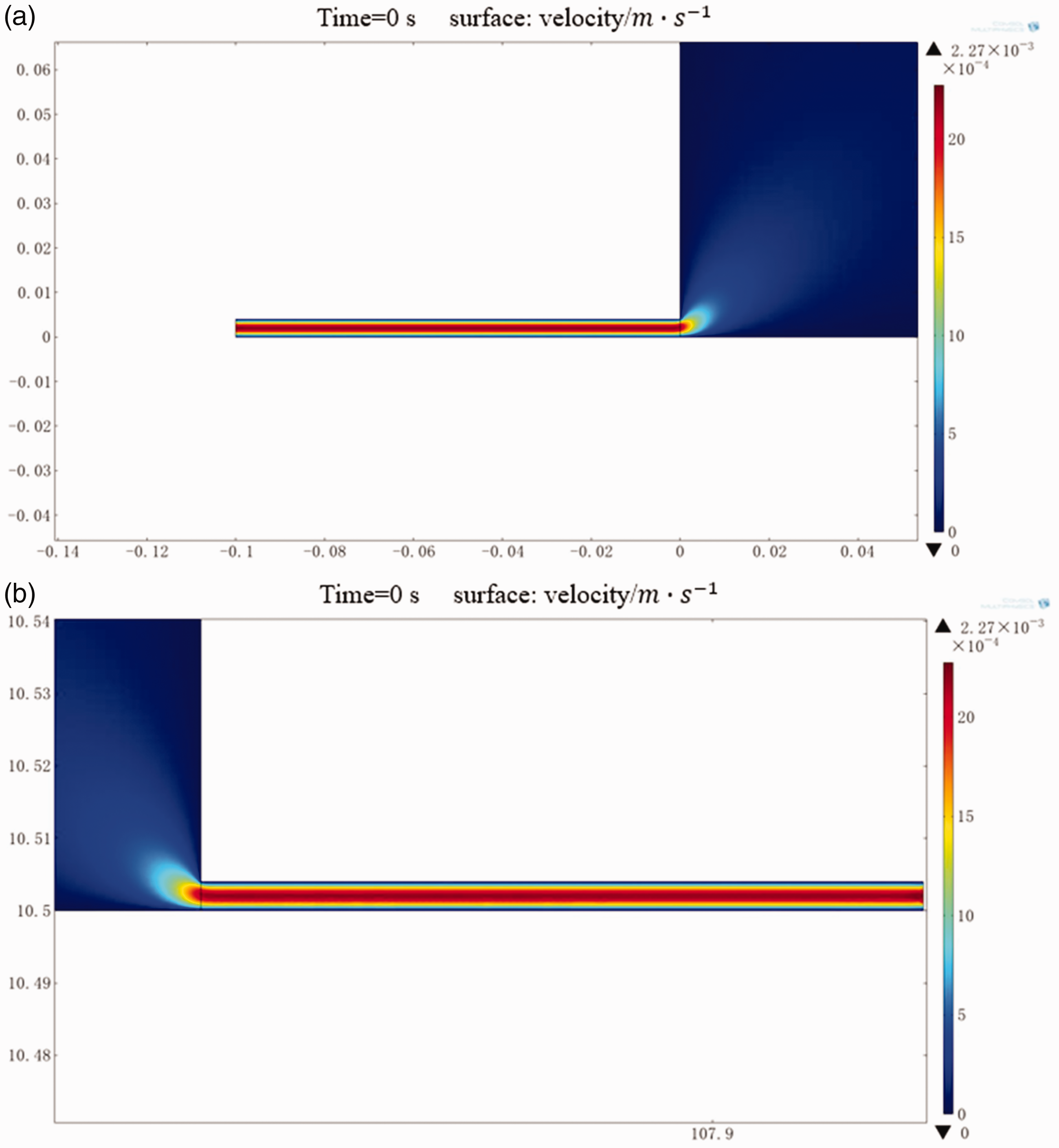
The lubricant compensation system is realized mainly by the spring pushing annular piston. The diameter of the piston is 140 mm, the internal diameter is 85 mm, and the maximum working stroke is 172 mm. Using the volume calculation formula of the annular space, the maximum oil volume that can be compensated is 1670.87 mL. The calculation results of the leakage amount and the sustainable working time are shown in Table 1.
Relationship of inner pressure and leakage.
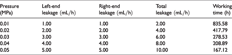
As can be seen from the table, the amount of lubricant leakage increases with the increase in internal pressure. At the same time, the increase in leakage also reduces the continuous working time of the tool. Because the model used in this analysis does not consider the influence of vibration, temperature, wear, and other factors on the overall seal performance, the wellbore trajectory control tool will be affected by the above factors in actual work. However, when the pressure in the seal chamber is greater than 0.037 MPa, the dynamic seal will fail, so the pressure should be limited to within 0.03 MPa. Therefore, the actual leakage should be around 6 mL/h.
Leakage tests based on simple test bench
In order to test the actual deflection ability of the tool and the leakage, a simple test bed for wellbore trajectory control tool is designed. The structure of the bed is shown in Figure 12.

Sketch of test bed.
Fix the wellbore trajectory control tool on the test bed. The internal electronic equipment is calibrated after the tool is placed horizontally. Place measuring cup on the upper and lower ends of the tool to contain the leaked lubricant. Change the rotation speed of the tool spindle to measure the leakage. Set the initial rotation speed to 20 r/min, increase the rotation speed by 20 r/min every 1 h, and get lubricant volume in measuring cup. The test results are shown in Table 2.
Result of test.
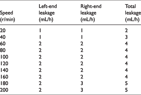
Based on the test results, it can be seen that the amount of lubricant leakage is similar to the simulation results. However, it can be seen from the test results that the leakage at both ends of the tool has a certain relationship with the rotation speed. When the speed is lower than 60 r/min, the leakage is small; when the speed is higher than 60 r/min and lower than 160 r/min, the leakage fluctuates around 4 mL/h and is relatively stable; and when the rotation speed is between 160 and 200 r/min, the leakage increases significantly.
Conclusion
The wellbore trajectory control tool seal system contains a lubricant supplement system with a complex sealing structure. The lubricant mainly leaks at the contact between the sealing lip and the rotary shaft. In order to predict the amount of lubricant leakage, it is assumed that the contact part between the sealing lip and the rotating shaft is a fixed-length gap, and a steady gap flow calculation method is used to calculate the leakage. The overall leakage analysis model of the wellbore trajectory control tool was established. The overall leakage of the tool under different internal pressure conditions is analyzed, and gets some conclusions as follows:
A seal system lubricant leakage predicting method that considers the contact between the sealing lip and the rotary shaft as a fixed-length gap was proposed. When the tool spindle rotation speed is less than 200 r/min, the prediction results of this method are close to the experimental results, which can be used for leakage rapid prediction of the well trajectory control tool seal system. The analysis of the contact between lip seal and rotary shaft shows that when the compression displacement is reached 0.7 mm, the deputy lip has just contact with the rotating shaft. If the compression displacement continues to decrease, the deputy lip disengages from the rotary shaft resulting in seal failure. The leakage volume reaches the maximum under this condition. The size of the hypothetical gap is obtained, which is 0.1 mm in length and 1 µm in height. If the sealing rubber material does not change, this gap size result can be directly substituted into formula (3) to quickly calculate the leakage.
Footnotes
Handling Editor: James Baldwin
Author note
The data underlying this article are available by agreement with our partners.
Declaration of conflicting interests
The author(s) declared no potential conflicts of interest with respect to the research, authorship, and/or publication of this article.
Funding
The author(s) disclosed receipt of the following financial support for the research, authorship, and/or publication of this article: This work of the article was supported by the Scientific Research Program of Hubei Education Department (Q20181315) and Hubei Technology Innovation Project (major project) (2019AAA010) as well as Yangtze University Excellent Master Degree Thesis Cultivation Program (YS2018023).