
Abstract
This paper explores three methods for electro-hydraulic actuator redundancy management strategies based on fuzzy aggregation, Mamdani’s fuzzy logic rules, and fuzzy neural network theory. These intelligent management schemes and implementation strategies are studied for a designed hardware-independent redundancy loop. Fault identification and isolation and system reconstruction are performed by combining fuzzy clustering with Mamdani’s fuzzy control, a fuzzy neural network, and redundancy management. Simulation analyses of the three algorithms are performed and loop simulation models are established based on the analysis algorithm. The methods proposed in this paper can solve the problem of misjudgment encountered in traditional methods and can also avoid uncertain states in the system.
Keywords
Introduction
With the continuing development of intelligent computer technology, redundancy technology is being used increasingly in aerospace applications.1–5 The electro-hydraulic servo actuator, as an important component of an aircraft, is also being developed to include redundancy.6–8 Actuators in aircraft must be reliable because any error will cause flight failure or could lead to a crash. Redundancy techniques provide an important means to enhance system reliability. A good management strategy is important to guarantee realization of the functionality of a redundant actuator.9–12 Gohil et al. studied redundancy management methods in avionics communication devices. 13 Ramos et al. applied a fuzzy logic method based on optimization to a redundant manipulator system and reported good results. 14 Mayorga and Chandana applied a fuzzy neural network method to a redundant control system and their results were verified through simulations. 15 Zhang and Deng studied redundant rules based on propositional logic and proposed three reduction algorithms. By reducing these rules, they optimized their rule-based knowledge base structure and improved the time and space efficiency of knowledge-based reasoning. 16 . Orr and Slegers proposed a general method for allocation of the redundant thrust vector swing instructions for multidrive launch vehicles and reported good results. 17 At present, the research on redundancy management strategies only concentrates on three aspects: guaranteed by hardware design, failure absorption and by simple comparison; these approaches mainly focus on fault monitoring and identification without performing in-depth strategic analysis and system online reconstruction research.18–27 Unlike the application of fuzzy theory in intelligent control, fault diagnosis and other fields,28–39 this paper proposes three types of redundancy management method for electro-hydraulic actuators based on fuzzy theory and verifies the effects of the proposed methods through simulation analyses. The proposed methods also alleviate the misjudgment problem of the traditional mathematical comparison method when dealing with the redundant voting problem.
Redundancy design and analysis
The electro-hydraulic actuator in this paper uses four-redundancy hardware. When one or two redundant failures occur, the system must then quickly isolate the fault and decide on the correct signal. The reliability and effectiveness of the redundancy management strategy (RMS) used thus determines the working quality and stability of the electro-hydraulic actuator directly.
A schematic of an aircraft’s electro-hydraulic actuator is shown in Figure 1. The actuator output position potentiometer signals pass into the analog-to-digital (A/D) converter after processing. The digital signal processor (DSP) subsequently processes the deviation signals of the instruction and the position using a specific algorithm and outputs the desired signal, which then drives the actuator’s action after digital-to-analog (D/A) conversion, voltage/current (U/I) transformation and amplification processing. This is a closed loop system in which the actuator’s output position can follow the input command signal in real time.
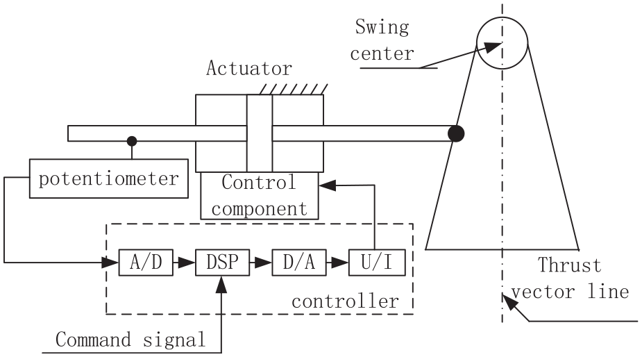
Schematic of aircraft electro-hydraulic actuator.
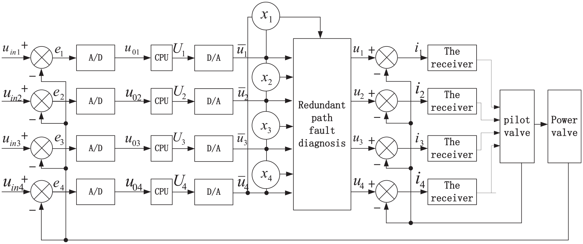
The redundancy designed in the system includes the potentiometer, the A/D converter, the DSP, the D/A converter, the U/I converter and the control components, and all of these devices are four-redundancy hardware. The four-redundancy potentiometers, which have four independent power supplies, can also be integrated into the overall design of the structure. The control component is a direct-drive two-stage servovalve, which has a four-redundancy pilot valve. A diagram of the control loop of the four-redundancy electro-hydraulic actuator is shown in Figure 2.

Four-redundancy control loop system for an aircraft actuator.
The input to the aircraft actuator’s redundancy system is determined using four independent instruction signals and the correct drive current value is obtained through use of the controller redundancy management logic. The control component’s working state is controlled by the hydraulic valve redundancy management logic. The system’s advantages include hardware-independent redundancy, zero interference, and high system reliability.
The redundancy management logic can distinguish the correct signals from fault signals using specific algorithm strategies and can then output the correct value to the subsequent system operation using a fault elimination strategy.
Proposal of a new RMS
Traditional four-redundancy management logic strategies sort signals by size. Then, these strategies calculate the differences between the maximum and minimum values and the differences between the adjacent values after sorting. The values of the difference parameters
The redundant management logic principle is illustrated in Figure 3, which shows that
Redundant voting principle.
If
Four-redundancy fault locations.

0 means no more than the threshold δ; × means more than the threshold.
The defects in this judgment method are evident. When
Other rules have also been found to have similar judgment “error” problems. In addition, when
This disposal method is prone to misjudgment and thus affects the steady-state accuracy and dynamic characteristic output of the system. Therefore, a new RMS is required to solve the redundancy management problem of aircraft electro-hydraulic actuators. This paper introduces fuzzy logic theory, which describes and studies fuzzy objects using clear mathematical methods.
Fuzzy clustering rules method
Unlike the supervised learning process of pattern classification, fuzzy clustering is an unsupervised learning method that can maximize the historical or real-time data from a process. Fuzzy clustering can also classify the process by establishing fuzzy similarity relations. Fuzzy clustering analysis classifies data according to specific requirements or rules. To summarize, data with similar characteristics within a group of data are classified into a category and the entire data family can then be divided into several groups with different characteristics. The principle of fuzzy clustering is to make the data differences between the different data types as large as possible while also making the data differences within each class as small as possible.
The four redundant input signals and the control objects in the control loop of the electro-hydraulic actuator system are all the same. Theoretically, the data generated by the intermediate links for each redundancy should be consistent or the deviation should not be significant. Regarding each step in every data branch as an independent group means that when a branch of a data link encounters problems, the system can make judgments quickly using the fuzzy clustering method that allow it to identify the fault point or faulty branch rapidly and then isolate the fault or reconstruct the system output.
Extraction of evaluation indexes
Numerous redundant links are present in the four-redundancy system of the actuator and the system involves multiple performance and technical indexes. In the performance evaluation index of the redundant signals, the principles of comprehensive coverage systems should be reflected and the principles of maneuverability and quantifiable realizations should also be considered. Four redundancy circuits (labeled I, II, III, and IV) contain the redundant loop position feedback, A/D output, central processing unit (CPU) output and D/A output values.
The redundant path data to be processed for voting are
Data weighting and standardization
The value range for each signal in the control redundancy loop is different, so the original data should be standardized for convenience of comparison and to ensure good application of the signal classification approach based on the fuzzy clustering method.
Each data group is processed using a “translation-standard deviation transformation”.


where
After the “translation–standard deviation transformation”, the mean value and the standard deviation of each index datum become 0 and 1, respectively. However, at this time, the index data cannot be determined on the interval [0, 1] and the data are then processed as a “range transformation–normalization” procedure in accordance with the following formula. The normalized data
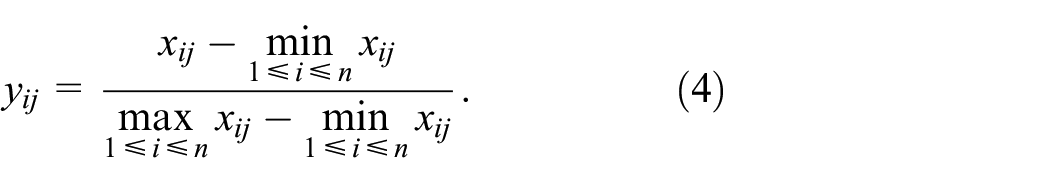
After the standard deviation transformation of the indicator signal and the normalization process, the data dimensions are unified and all analysis data fall into the interval [0, 1]. The fuzzy number transformation of the signal evaluation value is completed, thus creating conditions for further fuzzy analysis and processing.
The weight of each signal datum in the redundant loop is

Construction of the fuzzy similarity matrix
It is necessary to establish a fuzzy relation matrix for the fuzzy clustering analysis. Common methods used to construct a fuzzy similarity matrix include the quantitative product, correlation coefficient, maximum and minimum, arithmetic mean minimum, geometric mean minimum, absolute value index, and absolute value subtraction methods. The correlation coefficient method is selected for use in this research.

where
Then, the similarity matrix is obtained.

The equivalent matrix must then be found: if
The similarity parameter
Under the assumption that the input instructions given by the upper level system are all normal, the vote on the feedback signal can then be equivalent to the deviation between the instruction and the feedback, and a sinusoidal input is used for the simulation. One gain link, a proportional-integral-derivative (PID) link and another gain link are used to simulate the A/D conversion, the CPU algorithm and the D/A conversion, respectively, and a MATLAB simulation model is established as shown in Figure 4.
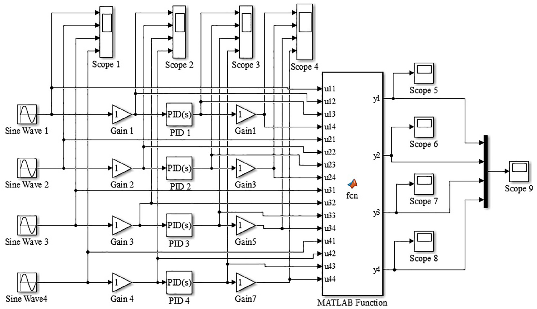
Simulink simulation model based on fuzzy aggregation method.
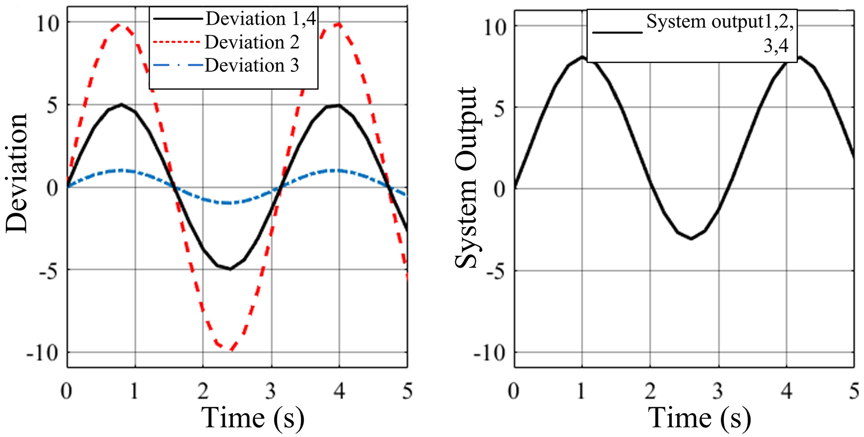
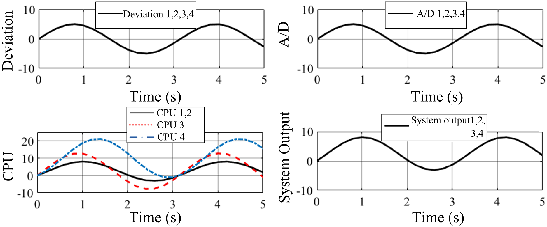
The simulation results for the four-redundancy system based on the fuzzy aggregation method are shown in Figures 5 to 8. The results show that the redundant system can still obtain consistent output signals in the cases of one-way and two-way faults.

Output results for a deviation signal fault.
Output results for two deviation signal faults.

Output results for a CPU signal fault.
Output results for two CPU signal faults.
Mamdani’s fuzzy logic method
Three fuzzy logic inference systems are commonly used; these systems are the pure, Mamdani, and Takagi–Sugeno (T-S) fuzzy logic systems. The inputs and outputs of a pure fuzzy logic system are fuzzy sets and the inputs and outputs of most engineering systems are accurate in reality, so a pure fuzzy logic system cannot be applied to practical engineering scenarios. To solve this problem, researchers proposed the use of Mamdani’s fuzzy reasoning system with a fuzzy generator and a fuzzy eliminator as the basis of the pure fuzzy logic system. Additionally, the Japanese researchers Takagi and Sugeno introduced a fuzzy logic system with precise values after the fuzzy rule conclusion and called it the T-S fuzzy logic system.40–42
Mamdani’s fuzzy theory was first proposed by Ebrahim Mamdani in 1975 for control of steam engines. In engineering applications, the inference output is expected to be a specific control quantity or numerical value. In the application of the Mamdani fuzzy inference system, the output obtained after every rule inference is the membership function or a discrete fuzzy set of variables. After synthesis of the results for multiple rules, the fuzzy set for each output variable must be defuzzified to obtain the desired output from the actual system.
The Mamdani fuzzy system is composed of four parts, including fuzzification, the knowledge base, fuzzy reasoning, and defuzzification, as illustrated in Figure 9. In the fuzzification step, the precise input quantity is transformed into a fuzzy quantity by creating fuzzy sets. The knowledge base generally includes a membership function and the fuzzy rule base, and its main function is to aid in completion of the fuzzy logic reasoning. In the defuzzification step, the output from fuzzy reasoning is converted into the actual clear output required using the knowledge base.

Composition of Mamdani’s fuzzy system.
A schematic of Mamdani’s three-dimensional fuzzy system is shown in Figure 10. The parameters
1. Fuzzification: In this process, the input variables

Four-dimensional fuzzy system.
“Small, medium, and large” fuzzification is performed in accordance with the size of the input variable value. In this study, a trapezoidal fuzzy membership function was selected because of the discretization and error characteristics of the signal from the research object of the intelligent control strategy while also ensuring the independence and continuity of each channel and thus avoiding unnecessary reconstruction as far as possible.
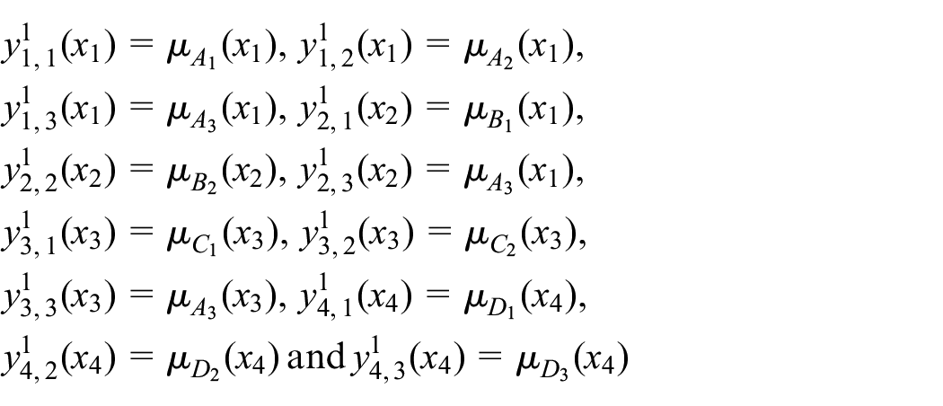
2. Establishment of the fuzzy rule base: the fuzzy rule base is composed of several “if–then” logic rules. For example, the form of the logic rule
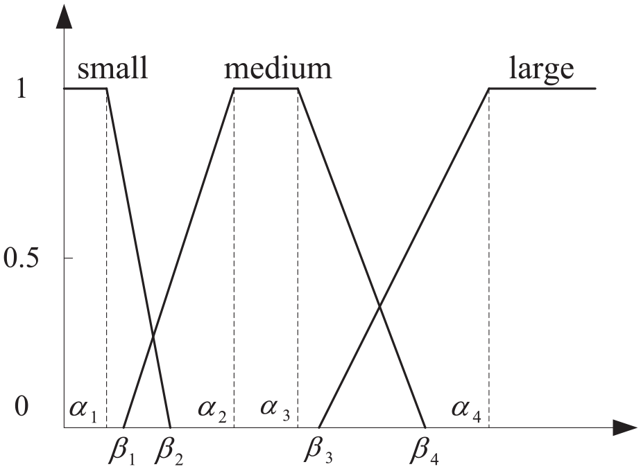
Input membership function graph.
If
3. Fuzzy processor: The fuzzy processor performs fuzzy reasoning on the sets of the input fuzzy languages

where
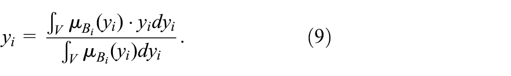
4. Defuzzification: The output fuzzy quantity from the fuzzy processor is transformed into a clear output quantity in the domain
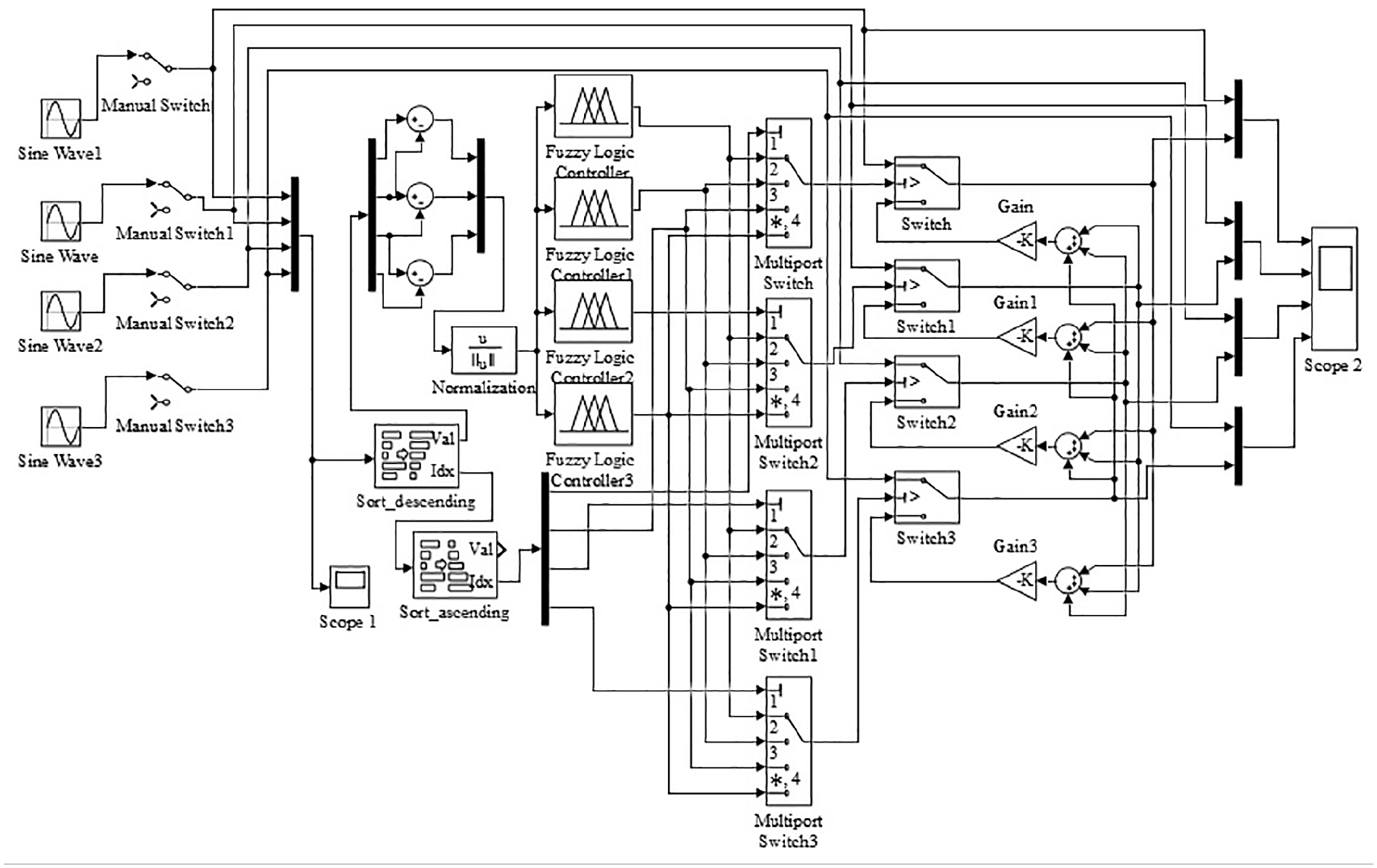
The four-redundancy management simulation model based on Mamdani’s fuzzy logic is then established as shown in Figure 12.

Redundant voting simulation model based on Mamdani fuzzy logic.
A method based on expert knowledge and experience is used to determine the fuzzy rule base, as shown in Table 2.
Table of fuzzy rules.

In Table 2, S means small, M means medium and L means large. “1” means a normal output and “0” means circuit failure.
Four sinusoidal waves are used to represent a four-way redundant signal and a “Sort_descending” and “Sort_ascending” module is used to sort the four-way signal and record the path number for each signal. The “fuzzy logic controller” has four inputs and four outputs.
The simulation outputs for one-way and two-way faults for the four-way redundant system based on Mamdani’s fuzzy logic are shown in Figure 13 and Figure 14, respectively. These results show that the redundant system can still obtain consistent output signals in the cases of the one-way and two-way faults.

One-way fault output simulation using Mamdani’s method.
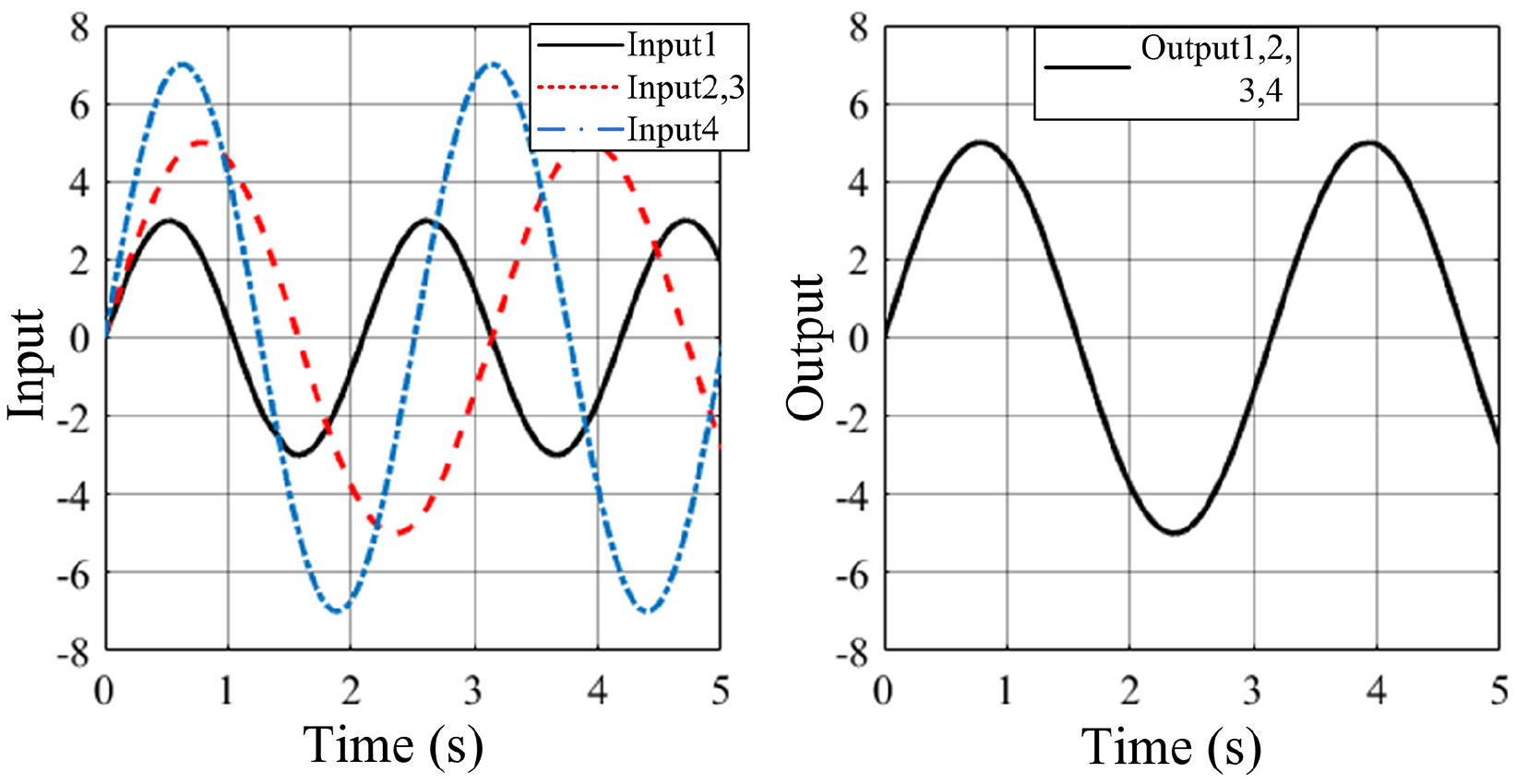
Two-way fault output simulation using Mamdani’s method.
Takagi–Sugeno fuzzy neural network method
Unlike Mamdani’s strategy, in which the output is a fuzzy set, the T-S output is a linear function of the input variables. The fuzzy system has some disadvantages, including a lack of active learning and poor adaptability. A neural network is a mathematical model that simulates the mode of thought of a human brain and has a self-learning function. Neural networks and fuzzy logic systems provide an effective means to solve the problems of system voting and reconstruction in redundancy management. Using the self-learning ability of neural networks, fuzzy systems can be modified to enhance their self-learning and adaptive capabilities. With the help of the neural network, the fuzzy rules can be generated and the membership functions can be adjusted to make the fuzzy system more intelligent and more efficient. The fuzzy reasoning and defuzzification processes of the fuzzy system are realized using neural networks. An adaptive network-based fuzzy inference system (ANFIS) can be formed through deep integration of a neural network and a fuzzy inference system. The ANFIS maximizes the advantages of the two systems and makes up for their shortcomings. The construction of an ANFIS fuzzy neural network model is shown in Figure 15.

ANFIS structure.
This paper discusses four-input and four-output systems, with four input signals denoted by
Layer 1: Fuzzification. Each node in this layer is an adaptive node with a corresponding node function.
where

where
Layer 2: Fuzzy set operation (calculation of the applicability of each rule). Every node in this layer is a fixed node and the output is the algebraic product of all input signals required to realize the fuzzy set operation of the premise part.

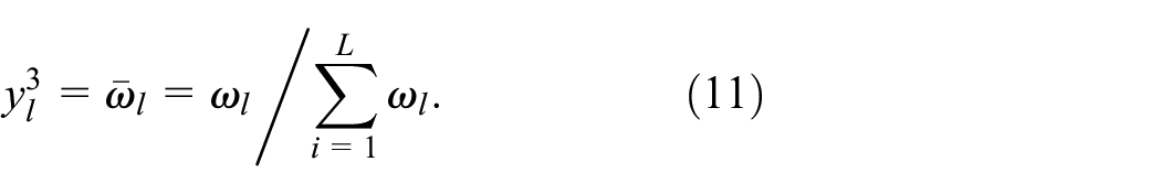
Layer 3: The application (excitation intensity) of each rule is normalized and the nodes in this layer are all fixed nodes. The normalized applicability of rule
Layer 4: Defuzzification layer. The output of each rule is calculated. Each node in this layer is an adaptive node with a corresponding node function:

where
Layer 5: The system output is computed and the layer is a fixed single node.
The total fuzzy system output, which is equal to the sum of the outputs of all the rules, is calculated and the ANFIS output is

The antecedent and consequent parameters are unknown here. Training of the ANFIS with the hybrid learning algorithm allows the values of these parameters to be obtained, thus enabling the goal of fuzzy modeling to be achieved. The ANFIS uses the hybrid algorithm to modify each parameter and begins by assigning the initial value to
The ANFIS simulation model of the fuzzy reasoning system is then established based on an adaptive neural network, as shown in Figure 16.
ANFIS simulation model.
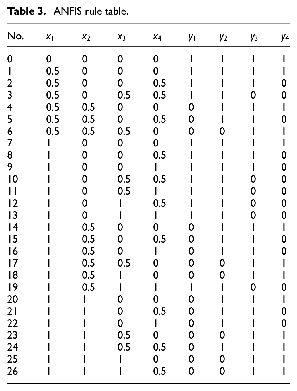
The fault signal of the system’s four-channel signal is summarized and the judgment threshold is then set. Using the differences between various signals, each signal is judged to be correct or incorrect. The output enabling signal is valid when the output is “1” and is invalid when the output is “0”. When a channel is defined as being invalid, the signal in this channel will be replaced with a new correct signal to drive the system to continue to work based on specific strategies. The ANFIS rules are listed in Table 3.
ANFIS rule table.
The simulation results for the four-way redundant system based on the ANFIS method are shown in Figure 17 and Figure 18. The results show that the redundant system can still obtain consistent output signals in the cases of one-way and two-way faults.

ANFIS method: one-way fault simulation output.

ANFIS method: two-way fault simulation output.
Conclusions and outlook
Using an intelligent algorithm as a basis, the redundant signal management strategy for the control loop of an electro-hydraulic actuator for aircraft applications was studied. In accordance with the differences in redundant decision logic, the following three intelligent management strategies were studied: ① an RMS based on fuzzy aggregation logic, ② an RMS based on Mamdani’s fuzzy logic, and ③ an RMS based on T-S fuzzy neural network logic. Simulation analyses of the three algorithms were performed and a loop simulation model was established on the basis of the analysis algorithm.
The methods proposed in this paper can solve the problem of misjudgment that occurs in traditional methods and avoid uncertain states in the system. From the analysis and the research described in this paper, the following conclusions were drawn:
The RMS based on fuzzy aggregation can classify and distinguish the system signals by taking a single loop as a group of signals and then determining the same type of aggregation among the signals of the different path groups. This approach can manage redundant signals effectively, isolate fault signals quickly and thus determine the reconstruction and regeneration of the system.
The RMS based on Mamdani’s fuzzy logic can judge the terminal signals of redundant paths and enable fast isolation of fault signals to help reconstruct and regenerate the system.
The RMS based on the fuzzy logic of a neural network can manage the redundant models. The introduction of a neural network can apply experience and knowledge effectively, reduce human interference and improve the system’s self-learning capability and intelligence.
When compared with older technology, the main advantages and characteristics of the approach in this study include the following:
In this study, an intelligent management strategy is used to replace the traditional mathematical comparison method and achieve redundant voting, thus allowing better continuity and higher accuracy to be obtained.
The method proposed in this study has a deep self-learning ability that can allow the difficulty of training to be increased flexibly, reduce the problem rate and degree of harm of misjudgments, and make the system more adaptable.
The intelligent redundancy management strategy proposed in this study can perform fault isolation and reconstruction of the actuator system and improve the system reliability. However, there are still some important issues in this study that have not been discussed thoroughly here. The following gives a brief description of these issues to provide a clear direction and targets for further research.
When two channels of the system have exactly the same fault simultaneously, the method proposed in this study cannot isolate the fault effectively and reconstruct the system. This is because the proposed method is not completely divorced from the principle that, “the minority is subordinate to the majority”. When the situation above occurs, the system is prone to misjudgment. In future studies, to avoid this situation, it will be necessary to perform a prior estimation of the system output and then correct the system in time when the actual output deviates; this will necessitate study of an accurate system “output/input” model.
When the learning rules of the intelligent strategy in this study are designed, they are based on specific discrete points. Although this coverage is taken into account, the depth of learning must still be explored to ensure that the independence and continuity of the coefficient output are maintained more effectively. At the same time, higher output accuracy can be achieved when the system is reconstructed after failure. As part of the future work, the continuous training rule design will be studied to enhance the accuracy and adaptability of the system.
Footnotes
Handling Editor: James Baldwin
Declaration of conflicting interests
The author(s) declared no potential conflicts of interest with respect to the research, authorship, and/or publication of this article.
Funding
The author(s) received no financial support for the research, authorship, and/or publication of this article.