
Abstract
Typically, the motion of the output link of the mode clamping mechanism has reciprocating linear motion, but the motion of the input link can be reciprocating rocking motion or reciprocating linear motion. In addition, the mold clamping mechanism must have a dead-position configuration for the mold at the closed position. This article focuses on the kinematic design of a mold clamping mechanism having an input link with reciprocating linear motion and having dead-position configuration at closed positions. First, four design concepts of mold clamping mechanisms are proposed based on the mechanism creative design methodology. Then, one of the design concepts is chosen as the design example to illustrate the kinematic design of the mode clamping mechanism with minimal maximum acceleration. According to the design requirements, the best design of the mode clamping mechanism of this article is better than the existing patent by reducing 43.5% acceleration and 18.6% driving force.
Keywords
Introduction
The usage of plastic products is becoming more and more extensive, how to increase the production and quality of plastic products has become a major research topic for engineering. The kinematic behavior of the injection molding machine will be required stricter than ever. In order to improve the stability of the production of plastic products, the vibration and noise during the production process must be reduced, and the life of machine must be extended. Hence, the kinematics of mold clamping mechanism must be analyzed first. Good kinematic characteristics of the mold clamping mechanism are the goal pursued manufacturing plastic products. Figure 1(a) and (b) shows the injection molding principle and injection molding machine. The injection molding machine includes forming section and injection sections. This article focuses on the design of mode clamping mechanism in forming section.
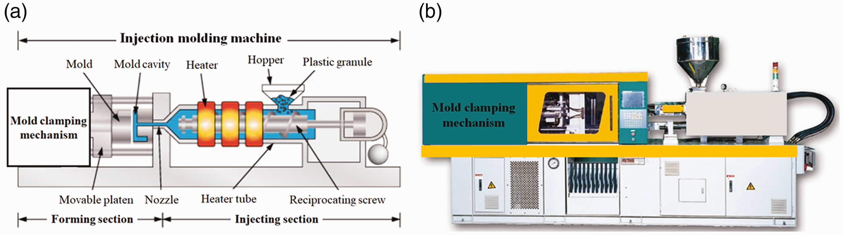
Injection molding machine: (a) injection molding principle and (b) injection molding machine.
Traditionally, the mold clamping mechanism has a dead-position configuration for the mold at the closed position. When the mold is in the open position, the mold clamping mechanism does not need to have dead-position configuration. This study focuses on the kinematic design of mold clamping mechanisms with minimal maximum acceleration for injection molding machine. First, four design concepts of mold clamping mechanisms are proposed based on the existing patents1–10 and the researches on the creative design.11–18 Then, one of the design concepts is chosen as the design example to illustrate the design process of the kinematic design of mode clamping mechanism with smaller maximum acceleration. Finally, according to the studies on the kinematics of mechanisms14,19–25 and design requirements, the best design of mode clamping mechanism of this article is better than the patent1 by reducing 43.5% acceleration and 18.6% driving force.
Mode clamping mechanism
At the beginning of this study, the topological characteristics of various mode clamping mechanism must be analyzed from the academic papers, catalogs, and technical reports. Typically, the motion of the output link of the mode clamping mechanism has reciprocating linear motion, but the motion of the input link can be reciprocating rocking motion or reciprocating linear motion. In addition, the mold clamping mechanism must have dead-position configuration for the mold at closed position.
Input link being a reciprocating linear motion
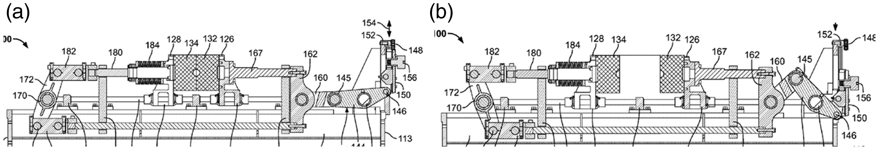
Figure 2 shows a patent1 of mode clamping mechanism with the motion of the input link being a reciprocating linear motion. Figure 3(a) and (b) shows the mode clamping mechanism at closed and open positions. When the mode clamping mechanism at closed position as shown in Figure 3(a), this mechanism is at dead-position configuration. According to Figure 3, this mechanism has six links and seven joints and 1 degree of freedom. The mechanism, shown in Figure 3, has three simple revolute joints (mark as A, D, and Oa), one multiple revolute joint (mark as C), and two sliding joints (between link 2 and Gr, between link 6 and Gr).

Mode clamping mechanism of servo-drive type injection molding machine:1 (a) closed position and (b) open position.
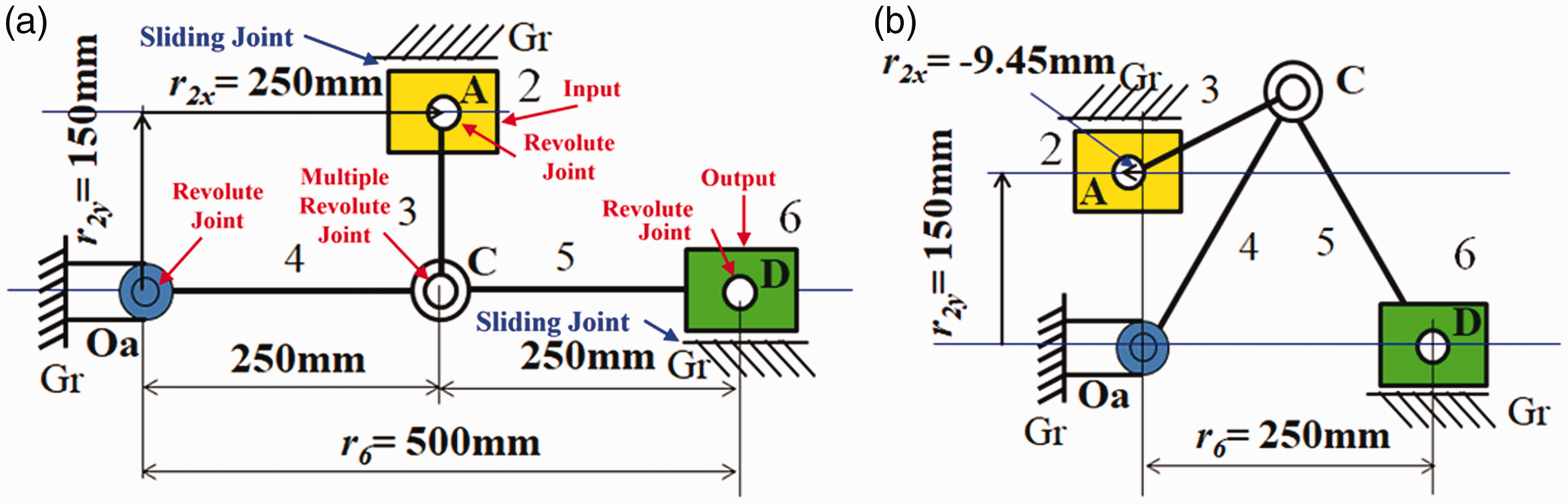
Kinematic skeletons of patent:1 (a) closed position and (b) open position.
Figure 4 shows another patent2 of mode clamping mechanism with the motion of the input link also being a reciprocating linear motion. Figure 5(a) and (b) shows the mode clamping mechanism at closed and open positions. Figure 5(a) shows the mode clamping mechanism at closed position, and this mechanism is at dead-position configuration. According to Figure 5, this mechanism has six links and seven joints and 1 degree of freedom. The mechanism, shown in Figure 5, has five simple revolute joints (mark as A, B. C, D, and Oa) and two sliding joints (between link 2 and Gr, between link 6 and Gr).

Driving device of controlling mode opening and closing for plastic molding machine:2 (a) closed position and (b) open position.
Kinematic skeletons of patent:2 (a) closed position and (b) open position.
Input link being a reciprocating rocking motion
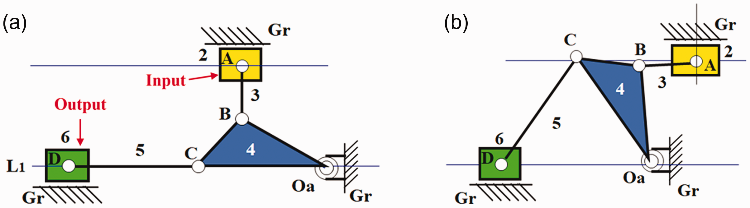
Figure 6 shows a patent4 of mode clamping mechanism with the motion of the input link being a reciprocating rocking motion. Figure 7(a) and (b) shows the mode clamping mechanism at closed and open positions. When the mode clamping mechanism at closed position is shown in Figure 7(a), this mechanism is at dead-position configuration. According to Figure 7, this mechanism has four links and four joints (three simple revolute joints and one sliding joint) and 1 degree of freedom. In Figure 7, Rin is denoted as input link and Sout is denoted as output link.
Modular clamp station:4 (a) closed position and (b) open position.
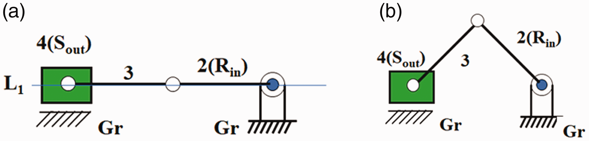
Kinematic skeletons of patent:4 (a) closed position and (b) open position.
Mode clamping mechanism with reciprocating linear input
Design concepts
This article focuses on the design of mode clamping mechanism with the motion of input link being a reciprocating linear motion. According to the researched of creative design methodology,11–18 four feasible design concepts, as shown in Figure 8(a)–(d), are proposed to be the mode clamping mechanism for injection molding machine, in which design concept I is the mold clamping mechanism of patent2 and design concept IV is the mold clamping mechanism of patent.1

Four design concepts of mold clamping mechanisms: (a) design concept I, (b) design concept II, (c) design concept III, and (d) design concept IV.
Kinematic design requirements
Based on the space constraints of mode clamping mechanism for injection molding machine, the design requirements are included as follows:
The displacement of output slider, Sout (from closed position to open position), must be 250 mm (Sout = 250 mm) within 1 s. According to Figures 3 and 5, the horizontal dimension of According to Figures 3 and 5, the vertical dimension of The displacement of input slider, Sin (from the closed position to open position), is limited to be 150–280 mm (
Kinematic analysis of patent
For the mode clamping mechanism of patent,1 Figure 9(a) and (b) shows the mode clamping mechanism and its corresponding vector coordinate system. According to Figure 9(b), the X and Y components of the two independent vector loops (vector loops 1 and 2) can be expressed as follows


Mode clamping mechanism of servo-drive type injection molding machine:1 (a) kinematic skeleton and (b) vector coordinate system.
According to Figure 9, if r2
y
= 150 mm, r3 = 150 mm, r4 = 250 mm, r5 = 250 mm, the following is obtained:
If θ4 = 0°, then θ3 = –90°, θ5 = 180°, r2
x
= 250 mm, and r6 = 500 mm. Figure 3(a) shows the dead-position configuration of mode clamping mechanism at closed position. If θ4 = 60°, then θ3 = 206.32°, r2
x
= –9.45 mm, θ5 = 120°, and r6 = 250 mm. Figure 3(b) shows the open position of this mode clamping mechanism.
Input motion of input slider
The motion curves include displacement, velocity, acceleration, and jerk curves of the machine part as a function of time. The displacement curve is a function of the movement of machine part relative to the time. The velocity curve and the acceleration curve can be obtained by first-differentiating and second-differentiating the displacement curve with respect to time. In the motion curve, the peak velocity Vmax, the peak acceleration Amax, and the jerk peak Jmax are called the motion characteristics of the motion curve. For an object of mass m moving at acceleration a, it will have inertial force F = ma. The larger inertial force, the larger possibility of moving objects produces vibration and noise. In order to consider safety, the peak acceleration amax of the motion curve is required to be as small as possible.
The input slider of mode clamping mechanism is driven by servo actuator so that the input motion can be controlled to have the motion wanted. In order to have better kinematic characteristics of mode clamping mechanism, the motion curve of input slider is required to be the MS motion curve.
MS motion curve
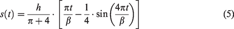
The MS motion curve (modified sinusoidal curve) is composed of two sinusoidal curves of different periods, which are symmetric curves, as shown in Figure 10. Their displacement, velocity, and acceleration functions are shown in equations (5)–(13).
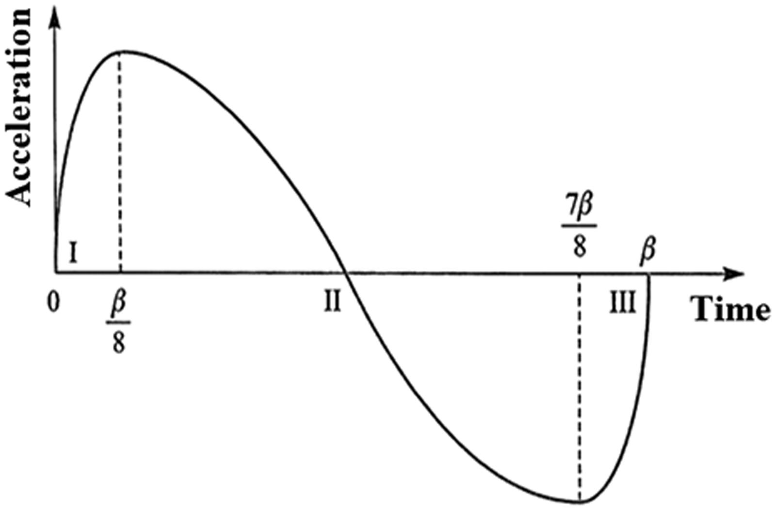
MS motion curve (modified sinusoidal curve).
(I) For


(II) For


(III) For


According to Figure 3, Sin = 259.45 mm. If the input slider is pushed to move 259.45°mm in 1 s (β = 1 s), based on equations (5)–(13), the displacement, velocity, and acceleration curves of the input slider can be drawn as Figure 11(a)–(c), respectively.

MS motion of mode clamping mechanism shown in Figure 3: (a) displacement, (b) velocity, and (c) acceleration.
Output motion of clamping mode
According to Figure 3, the displacement Sout of output clamping model is 250 mm. Then, based on equations (1)–(4), the velocity and acceleration curves of the output clamping mode can be drawn as Figure 12(a) and (b). The maximum velocity Vmax and maximum acceleration amax of the output clamping mode are 788 mm/s and 3977 mm/s2.

The characteristic curves of the output clamping mode of patent:1 (a) velocity, (b) acceleration, and (c) force ratio Fout/Fin.
Let the mechanical efficiency is 100%, the input power is equal to the output power, that is

According to the input velocity and output velocity shown in Figures 11(b) and 12(a), based on equation (14), the force ratio (Fin/Fout) is obtained and shown in Figure 12(c). The following is concluded:
For the mode clamping mechanism at initial position (closed position shown in Figure 3(a), the force ratio is 0 (Fin/Fout = 0); hence, the mechanism is at dead-position configuration. For the mode clamping mechanism at final position (open position shown in Figure 3(b), the force ratio is 2.79 (Fin/Fout = 2.79); it means the driving force (Fin) is 2.79 output load of clamping mode (Fout).
Dimensional synthesis and kinematic analysis
Kinematic analysis
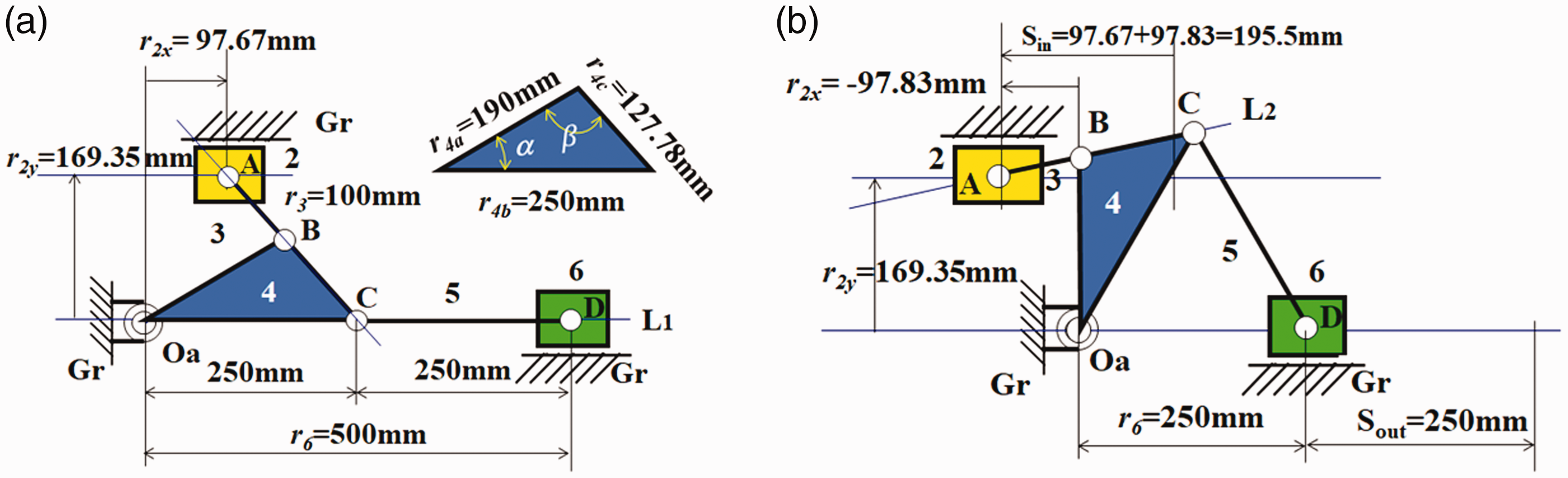
The purpose of this article is the kinematic design of mode clamping mechanism with minimal maximum acceleration and with minimal force ratio (Fin/Fout). In this research, the first design concept shown in Figure 8(a) is chosen as the example to illustrate the design process of mode clamping mechanism for injection molding machine. Figure 13(a) and (b) shows the mode clamping mechanism and its corresponding vector coordinate system. According to Figure 13(b), the X and Y components of the two independent vector loops (vector loops 1 and 2) can be expressed as follows


Mold clamping mechanism (I): (a) kinematic skeleton and (b) vector coordinate system.
Dimensional synthesis
According to Figure 13, if r2
y
= 169.35 mm, r3 = 100 mm, r4
a
= 190 mm, r4
b
= r5 = 250 mm, α = 30°, then r4
c
= 127.78 mm and β = 101.97°. According to equations (15)–(18), the following is obtained:
If θ4
b
= 0° (θ4
a
= 30°), then θ3 = –48.03°, r2
x
= 97.67 mm, θ4
c
= θ4
a
– π + β = –48.03°, θ5 = 0°, and r6 = 500 mm. Figure 14(a) shows the dead-position configuration (line L1) of mode clamping mechanism at closed position.
Dimensions of mold clamping mechanism (first design): (a) closed position (dead-position configuration, L1) and (b) open position. If θ4
b
= 60° (θ4
a
= 90°), then θ3 = 11.97°, r2
x
= –97.38 mm, θ4
c
= θ4
a
– π + β = 11.97°, θ5 = –60°, and r6 = 250 mm. Figure 14(b) shows the mode clamping mechanism at open position.
According to Figure 14(a) and (b), the following is concluded:
The displacement of output slider, Sout (from closed position to open position), is equal to 250 mm (Sout = 250 mm). The horizontal dimension of The vertical dimension of The displacement of input slider, Sin (from closed position to open position), is 195.5 mm (Sin = 195.5 mm) which is between 150 and 280 mm.
Output motion of clamping mode
If the input slider is pushed to move 195.5 mm in 1 s (β = 1 s) with MS motion (equations (5)–(13)), according to equations (14)–(18), the velocity and acceleration, and force ratio curves of the output clamping mode can be drawn as Figure 15(a)–(c), respectively. The maximum velocity Vmax, maximum acceleration amax, and maximum force ratio (Fin/Fout)max of the output clamping mode are 598 mm/s, 2412 mm/s2, and 2.26, respectively. The following is concluded:

The characteristic curves of the output clamping mode (first design): (a) velocity, (b) acceleration, and (c) force ratio Fout/Fin.
In this design, the maximum acceleration of output clamping mode is 2412 mm/s2 (amax = 2412 mm/s2). It is better than patent.1
For the mode clamping mechanism at closed position, Figure 14(a), the force ratio is 0 (Fin/Fout = 0); hence, the mechanism is at dead-position configuration (L1).
For the mode clamping mechanism at open position, Figure 14(b), the force ratio is 2.26 (Fin/Fout = 2.26); it means that the driving force (Fin) is 2.26 output load of clamping mode (Fout). It is also better than patent.1
For the mode clamping mechanism at open position, Figure 14(b), the force ratio is 2.26 (Fin/Fout = 2.26); it means that this position (Figure 14(b)) is not dead-position configuration (L2).
Clamping mode with minimal maximum acceleration
For the design concept (I) of mode clamping mechanism, as shown in Figure 8(a), according to the design requirements, the design process of mode clamping mechanism can be summarized as follows:
Step 1. Draw the skeleton of mode clamping mechanism at closed position with dead-position configuration, as shown in Figure 16(a), and decide the values of three design variables (r4
c
, r3, and γ), then the values of r2
y
and r2
x
,
c
can be calculated.
The skeleton of mold clamping mechanism (I): (a) closed position (dead-position configuration, L1) and (b) open position. Step 2. Draw the skeleton of mode clamping mechanism at open position with dead-position configuration, as shown in Figure 16(b), and calculate the values of r2
y
and r2
x
,
o
can be calculated, then the stroke of input slider is Sin = r2
x
,
c
– r2
x
,
o
. Step 3. Let the input slider is pushed to move Sin in 1 s (β = 1 s) with MS motion (equations (5)–(13)), according to equations (14)–(18), the velocity and acceleration, and force ratio curves of the output clamping mode can be obtained. Step 4. Change other values of three design variables (r4
c
, r3, and γ) and repeat steps 1–3 for designing the mode clamping mechanism with clamping mode having minimal maximum acceleration. 1. For the mechanism shown in Figure 16, if r4
c
= 127.78 mm and γ = 48.03° are fixed and r3 is changed from 73.79 to 120 mm, based on the above design processes, the corresponding maximum velocity Vmax, acceleration amax, and force ratio (Fin/Fout)max can be obtained. It is concluded that the shorter r3, the smaller maximum acceleration amax of clamping mode. 2. For the mechanism shown in Figure 16, if r2
y
= 150 mm and γ = 48.03° are fixed and r4
c
is changed from 30 to 73.79 mm, based on the above design processes, the corresponding maximum velocity Vmax, acceleration amax, and force ratio (Fin/Fout)max can be obtained. It is concluded that the larger r4
c
, the smaller maximum acceleration amax of clamping mode. 3. For the mechanism shown in Figure 16, if r2
y
= 150 mm and r4
c
= 80 mm are fixed and γ is changed from 48° to 90°, based on the above design processes, the corresponding maximum velocity Vmax, acceleration amax, and force ratio (Fin/Fout)max can be obtained. It is concluded that the smaller γ, the smaller maximum acceleration amax of clamping mode.

Case I
According to Figure 16, if r2
y
= 150 mm, r3 = 121.75 mm, r4
b
= r5 = 250 mm, r4
c
= 80 mm, and γ = 48°, according to equations (15)–(18), the following is obtained:
If θ4
b
=0°, then θ3 = –48°, r2
x
= 115.08 mm, and r6=500 mm. Figure 17(a) shows the dead-position configuration (line L1) of mode clamping mechanism at closed position.
The mold clamping mechanism (case I): (a) closed position and (b) open position. If θ4
b
= 60°, then θ3 = 204.08°, r2
x
= –64.35 mm, θ5 = –60°, and r6 = 250 mm. Figure 17(b) shows the corresponding mode clamping mechanism at open position.

When input slider is pushed to move 179.43 mm in 1 s, according to equations (14)–(18), the velocity, acceleration, and force ratio curves of the output clamping mode can be drawn as Figure 18(a)–(c), respectively. The maximum velocity Vmax, maximum acceleration amax, and maximum force ratio (Fin/Fout)max of the output clamping mode are 622 mm/s, 2409 mm/s2, and 2.42, respectively.

The velocity, acceleration, and force ratio curves of the output clamping mode (case I): (a) velocity, (b) acceleration and (c) force ratio.
Case II
According to Figure 16, if r2
y
= 150 mm, r3 = 93.2 mm, r4
b
= r5 = 250 mm, r4
c
= 80 mm, and γ = 60°, according to equations (15)–(18), the following is obtained:
If θ4
b
=0°, then θ3 = –60°, r2
x
= 163.4 mm, and r6 = 500 mm. Figure 19(a) shows the dead-position configuration (line L1) of mode clamping mechanism at closed position.
The mold clamping mechanism (case II): (a) closed position and (b) open position. If θ4
b
= 60°, then θ3 = 225.53°, r2
x
= –20.3 mm, θ5 = –60°, and r6 = 250 mm. Figure 19(b) shows the corresponding mode clamping mechanism at open position.

When input slider is pushed to move 183.7 mm in 1 s, according to equations (14)–(18), the velocity, acceleration, and force ratio curves of the output clamping mode can be drawn as Figure 20(a)–(c), respectively. The maximum velocity Vmax, maximum acceleration amax, and maximum force ratio (Fin/Fout)max of the output clamping mode are 684 mm/s, 2709 mm/s2, and 2.53, respectively.

The velocity, acceleration, and force ratio curves of the output clamping mode (case II): (a) velocity, (b) acceleration, and (c) force ratio.
Best case III
Since the design constraint of vertical 250 mm ≧ r2
y
≧ 150 mm, the shortest r3 is 73.79 mm. According to Figure 16, if r2
y
= 150 mm, r3 = 73.79 mm, r4
b
= r5 = 250 mm, r4
c
= 127.78 mm, and γ = 48°, according to equations (15)–(18), the following is obtained:
If θ4
b
=0°, then θ3 = –48°, r2
x
= 115.08 mm, and r6 =500 mm. Figure 21(a) shows the dead-position configuration (line L1) of mode clamping mechanism at closed position.
The mold clamping mechanism (best case III): (a) closed position and (b) open position. If θ4
b
= 60°, then θ3 = 212.52°, r2
x
= –62.22 mm, θ5 = –60°, and r6 = 250 mm. Figure 21(b) shows the corresponding mode clamping mechanism at open position.

When input slider is pushed to move 177.3 mm in 1 s, according to equations (14)–(18), the velocity, acceleration, and force ratio curves of the output clamping mode can be drawn as Figure 22(a)–(c), respectively. The maximum velocity Vmax, maximum acceleration amax, and maximum force ratio (Fin/Fout)max of the output clamping mode are 622 mm/s, 2246 mm/s2, and 2.27, respectively.
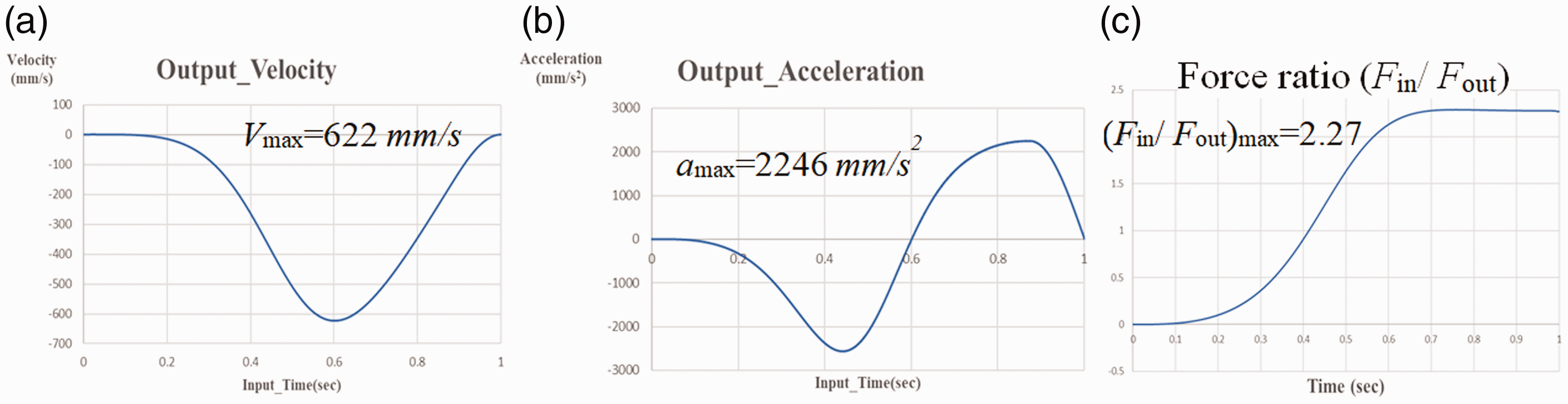
The velocity, acceleration, and force ratio curves of the output clamping mode (best case III): (a) velocity, (b) acceleration, and (c) force ratio.
Discussion
According to the above results, the following is concluded:
For the best design case III, the maximum acceleration of output clamping mode is 2246 mm/s2 (amax = 2246 mm/s2). The maximum acceleration of output clamping mode is reduced to 43.5% of patent.1 For the mode clamping mechanism at open position, Figure 21(b), the force ratio is 2.27 (Fin/Fout = 2.27), it means that the driving force (Fin) is 2.27 output load of clamping mode (Fout). The driving force (Fin) of this design is reduced 18.6% of patent1 (from 2.79 to 2.27).
Conclusion
This article focuses on the kinematic design of mold clamping mechanism having input link with reciprocating linear motion. First, four design concepts of mold clamping mechanisms are proposed based on the creative design methodology. Then, the design concept (I) is chosen as the design example to illustrate the kinematic design of mode clamping mechanism with minimal maximum acceleration. According to the design requirements, the last design of mode clamping mechanism is better than the first design by reducing 43.5% acceleration and 18.6% driving force. For the design concept (I), shown in Figure 16, the following is concluded:
The shorter r3, the smaller maximum acceleration amax of clamping mode. The larger r4
c
, the smaller maximum acceleration amax of clamping mode. The smaller γ, the smaller maximum acceleration amax of clamping mode.
Based on the same design process, the design concept (II) can be used to design the mode clamping mechanism with minimal maximum acceleration and minimal driving force. The results of this article will be the design reference of engineering when designing a mode clamping mechanism for an injection molding machine.
Footnotes
Handling Editor: James Baldwin
Declaration of conflicting interests
The author(s) declared no potential conflicts of interest with respect to the research, authorship, and/or publication of this article.
Funding
The author(s) received no financial support for the research, authorship, and/or publication of this article: The authors are grateful to Chum-power Machinery Co., Ltd. for the support of this research under 107AF094.