
Abstract
This study conducted an investigation on transverse quasi-static three-point loading on a circular aluminum tube and its characteristic plastic failure and energy-absorption behaviors. The thin wall thickness of the aluminum tube, the various diameter and thickness ratios (D/t) of the tube, and the tube length are important control parameters. Experimental data for different span length and thickness ratios of the tube were characterized and correlated to its plastic collapse behavior. A simulation model by computational analysis using ANSYS was also conducted as a comparative study. The results of the study found that transverse three-point bend loading (ASTM F290) of a circular aluminum tube underwent different stages of deformation, from initial pure crumpling to crumpling and bending, and finally, structural rupture. The results of master curve analysis found that regions of high energy absorption and low energy absorption can be classified with respect to the characteristic tubular deformation. High energy absorption deformation is correlated with a short span length and higher D/t ratio, and vice versa for low energy absorption deformation of the circular aluminum tube. Simulation analysis also predicted similar characteristic trends of deformation behavior in the experiment, with a less than 3% average coefficient of variation.
Keywords
Introduction
The energy absorption and destructive behavior of materials and structures plays a key role in the safety of structures after impact. In practical projects such as aviation, aerospace, automobiles, rail vehicles, offshore platforms, highway guardrails, and nuclear power plants, due to the need for safety protection, engineers must have strict requirements on the energy absorption performance of the structure. Many authors have studied energy absorption, and most energy absorption is done by ductile metals. As we all know, low carbon steel and aluminum alloys are commonly used materials. Therefore, this article mainly analyzes and studies aluminum alloys.
In this research field, many such related analyses have been carried out. In Olabi et al., 1 the energy absorber was studied in the form of a tubular deformation, mainly using low carbon steel and aluminum as test objects. The common behavior of its deformation is divided into five modes: lateral compression, transverse indentation, axial load, axial reversal, and axial split. Many of the earlier authors also studied and investigated the behavior of these five loading modes.2–9 In the case of lateral loads, Stronge 10 used a hemispherical indenter to study its deflection in both static and dynamic conditions. Although the author has considered the energy absorption problem caused by the collision of composite structures, it is only a single study on the expressway fence accident. Jones and colleagues 11 , 12 carried out those collision experiments under theoretical and lateral loads, with the steel tube size D/t 11 to 16. However, the author did not carry out actual verification but only obtained the theoretical calculation results and made a comparison with the previous experiments of other scholars. Thomas et al. 13 experienced experimental studies of wrinkling, wrinkling and bending, and structural fractures, respectively, for fixed spans and studied how the deformation mode changes with the D/t ratio of the tube. It can be seen that few authors have studied the analysis and comparison of circular aluminum tube materials after experimental analysis using simulation software. During the wrinkling and bending stages, a slight decrease in the load-deflection slope was observed. Then, the load continues to increase until it reaches the maximum value Pmax, and finally, the structure collapses. Similarly, Zhang Yong 14 studied the thin-wall structure filled with aluminum foam. However, the author has studied the deformation characteristics of an empty tube, uniform tube, and functionally graded foam aluminum tube under bending force, respectively. However, it should be considered that the aluminum tube should be analyzed in advance by simulation before the experiment is carried out, so as to save the research cost. Kardaras and Lu 15 conducted a finite-element analysis of the telescopic sag under concentrated loading operations. After that, Jafar et al. 16 studied the crushing of composite aluminum tubes under axial compression. Numerical analyses and experiments were used for the study. The author of this article draws conclusions and gives quantitative data for the correlation between finite-element analysis and experimental comparison. However, it has certain reference value. Wang et al. 17 have studied the compression and weld shaper performance of small direct aluminum alloy tubes. The type of aluminum alloy selected is 6063, and the measurement and analysis are carried out by means of optics. Sarkabiri et al. 18 carried out multi-objective optimization study on the crashworthiness of thin-walled slotted conical tubes filled with polyurethane foam. The author mainly studies tapered aluminum tubes with grooves on the inner and outer surfaces. Most aluminum tubes should be basically aluminum tubes without secondary processing, so the general applicability may not be very high. Acar et al. 19 mainly studied the evaluation of thin-walled aluminum tubes. Chu et al. 20 mainly studied the axial water forging sequence of 6063 aluminum alloy tubes. The author mainly expounds the structure of aluminum pipe through the forging process of an aluminum pipe. The relevant conclusions obtained need further verification. Lei et al. 21 mainly study the microstructure evolution and failure mechanism through an extrusion welding process. The characteristics of aluminum pipes were studied from the perspective of onlookers. However, the application prospect is not very broad.
Although many scholars have studied aluminum tubes. However, there are few comparative studies on aluminum tubes using ANSYS Wrokbench 18.0 simulation software and experiments. Therefore, this article mainly studies aluminum pipes by combining simulation and practice and draws relevant conclusions by combining theory, practice, and simulation, which lays a foundation for similar research in the future.
Theoretical analysis
For energy absorption and plastic failure studies of circular aluminum tubes, it can be assumed that there is a plastic strand, as shown in Figure 1.

Theoretical deformation of an empty aluminum tube under load: (a) assumed plastic deformation of circular aluminum tubes and (b) circular aluminum tube indented by the indenter.
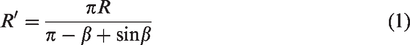
As shown in the figure, for the given central section geometry, since the circumference is still the same, the current part has a new radius R;
Plastic dent depth is

The width of the flat section is
The plastic limit bending moment of the current configuration of the central section can be calculated directly and is equal to


An approximate formula for calculating the derived bending moment M is

It is indicated that the plastic ultimate bending moment decreases linearly with the increase of the depth of the plastic depression, and the reduction height is
Therefore


Among them, N is the axial force generated in the tube, and NP is the plastic limit axial force of the round tube. Where δtl is the displacement of the loading head and
Experimental study
Experimental studies will be elaborated on in the following sections.
Experimental methods
The most aluminum tubes most commonly used in industry, 6061-T4, were used for this research. The ASTRON-8801, a universal aluminum pipe tensile tester, was used for experiments under quasi-static three-point bending test. Experiments were conducted with four different D/t ratios and four different span sizes, and the aluminum tubes were precisely machined to a specific size. These are also the most commonly used aluminum tube sizes in industry. In order to facilitate analysis and research, the test speed was set to a unified speed, regardless of acceleration and changes of the aluminum tube’s size. The 6061-T4 circular aluminum tube material parameters are shown in Table 1, the three-point bending experimental diagram is shown in Figure 2, and the experimental material parameters are shown in Table 2.
6061-T4 aluminum alloy material performance parameters.

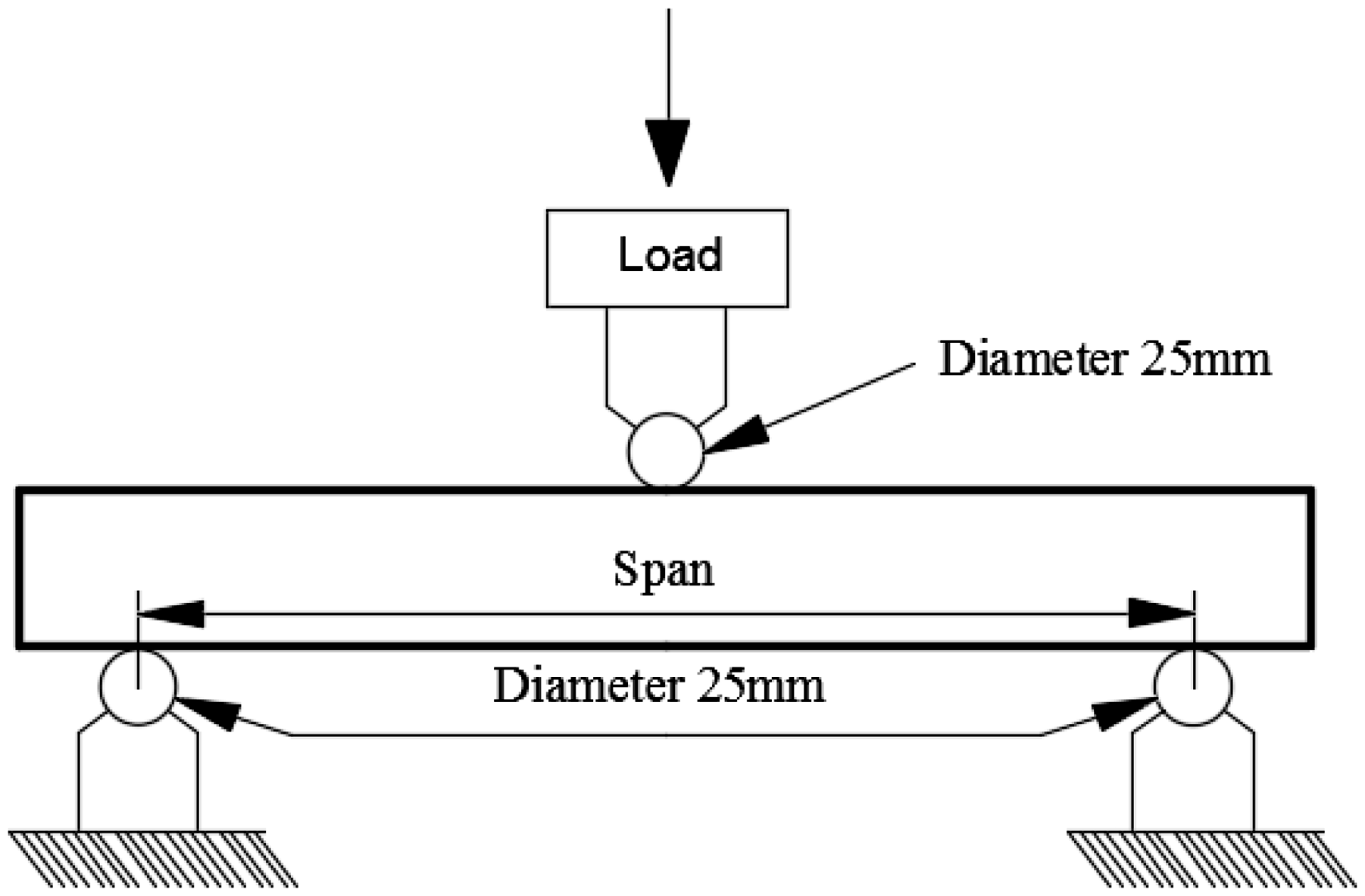
Aluminum tube three-point bending loading schematic.
6061-T4 circular aluminum tube experimental parameters.

Experimental results
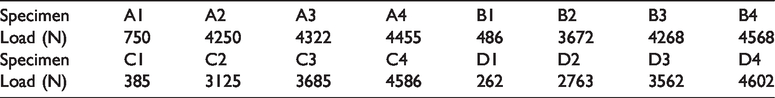
The experiment was carried out according to the parameters in Table 2. The measurement accuracy of ASTRON-8801, a universal aluminum tube tensile tester, is +0.5% for load and +0.25% for strain sensor readings. Sixteen groups of aluminum tube data sizes were tested, and the results of the applied load were obtained as shown in Table 3. The experimental diagram is shown in Figure 3.
Experimental results load parameters table.

6061-T4 circular aluminum tube experiment map: (a) the total length is 120 mm, (b) the total length is 180 mm, (c) the total length is 240 mm, and (d) the total length is 300 mm.
According to Table 3, it can be clearly concluded that with the same D/t ratio, the 6061-T4 circular aluminum tube has a smaller loading force as the span length increases. At the same span length, the loading force increases with D/t, especially in the period of D/t from 12.48 to 22.54, and the change of loading force is particularly obvious. However, the changes during the periods from 22.54 to 27.50 and from 27.50 to 36.32 are less obvious. For these numerical changes to be verified, and to be very intuitive to see, we must do relevant experiments on this value. The experimental results are shown in Figure 3.
As shown in Figure 3(a)–(d), three-point quasi-static experiments were performed on four different span sizes and D/t ratios for 120, 180, 240, and 300 mm lengths of 6061-T4 circular aluminum tubes, respectively. At the same time, comparative analysis will be performed through simulation in the following.
Simulation analysis and comparison
According to the two-dimensional figure of the three-point quasi-static load analysis of the aluminum tube shown in Figure 2, the Pro/E 5.0 software was used to model 14 types of aluminum tubes with different span lengths and different D/t ratios and imported into the ANSYS Workbench 18.0 for static analysis. Next, two kinds of quasi-static analysis of the three points in the ANSYS Workbench will be introduced: (1) under the same span size, the force conditions of different D/t ratios and the comparison analysis between the 3D model and the experiment; and (2) with the same ratio of D/t, the force condition under different conditions of span size and the comparison analysis between the 3D model and the experiment.
Prior to the analysis of the static properties, first, we set the boundary conditions and applied the load. We set the relevant material parameters of the circular aluminum tube 6064-T4 in Table 1 into the model. It was then meshed, and boundary conditions were imposed. Before the analysis of static characteristics, the rough model is shown in Figure 4.
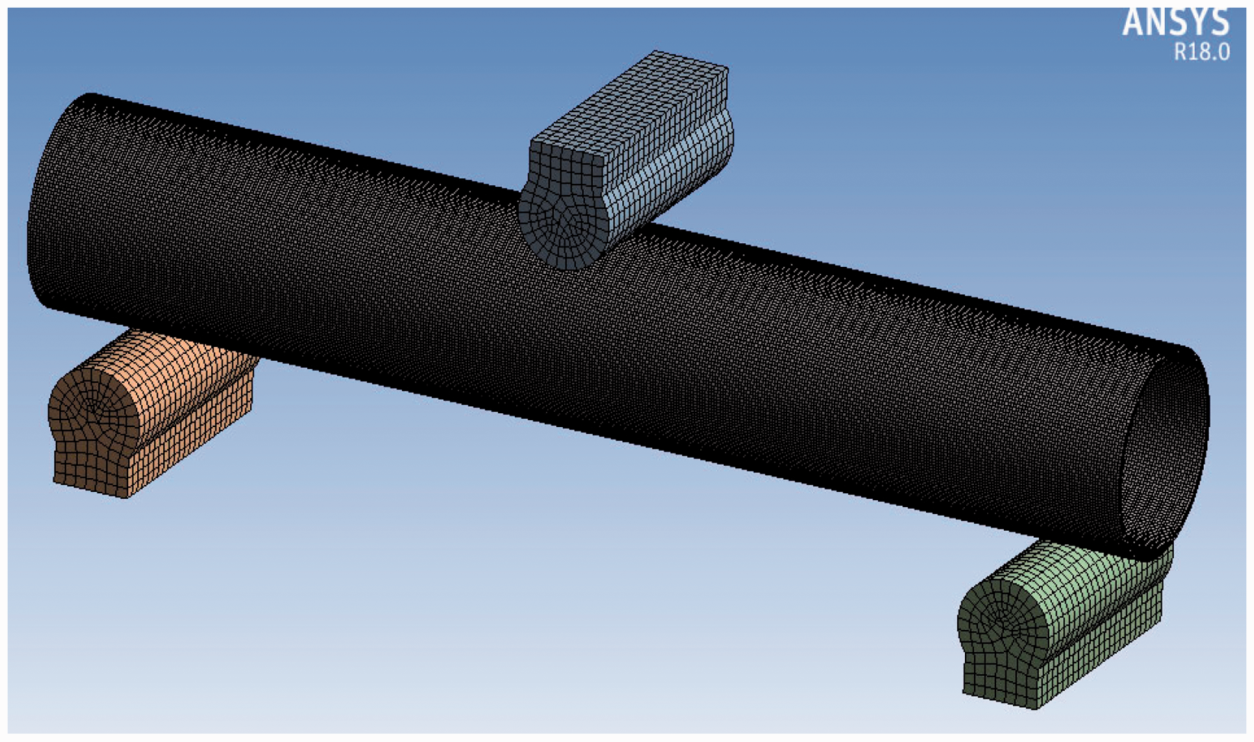
6061-T4 circular aluminum tube mesh.
Different spans, the same simulated comparison of D/t ratios
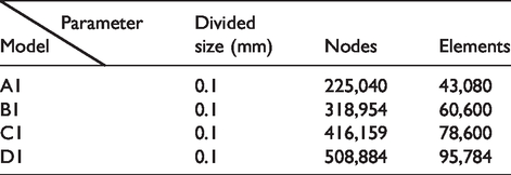
The next analysis will be for different spans, the same D/t ratio for simulation and comparison. The four models, A1, B1, C1, and D1, are extracted from Table 1 for analysis. The parameters are first set, then the boundary conditions and loads are applied, and finally, meshing is performed. The meshing parameters of A1, B1, C1, and D1 are shown in Table 4. The set up was then compared with the experiment. The comparison chart is shown in Figure 5. The convergence of mesh division is shown in Figure 6.
A1, B1, C1, and D1 meshing parameters table.
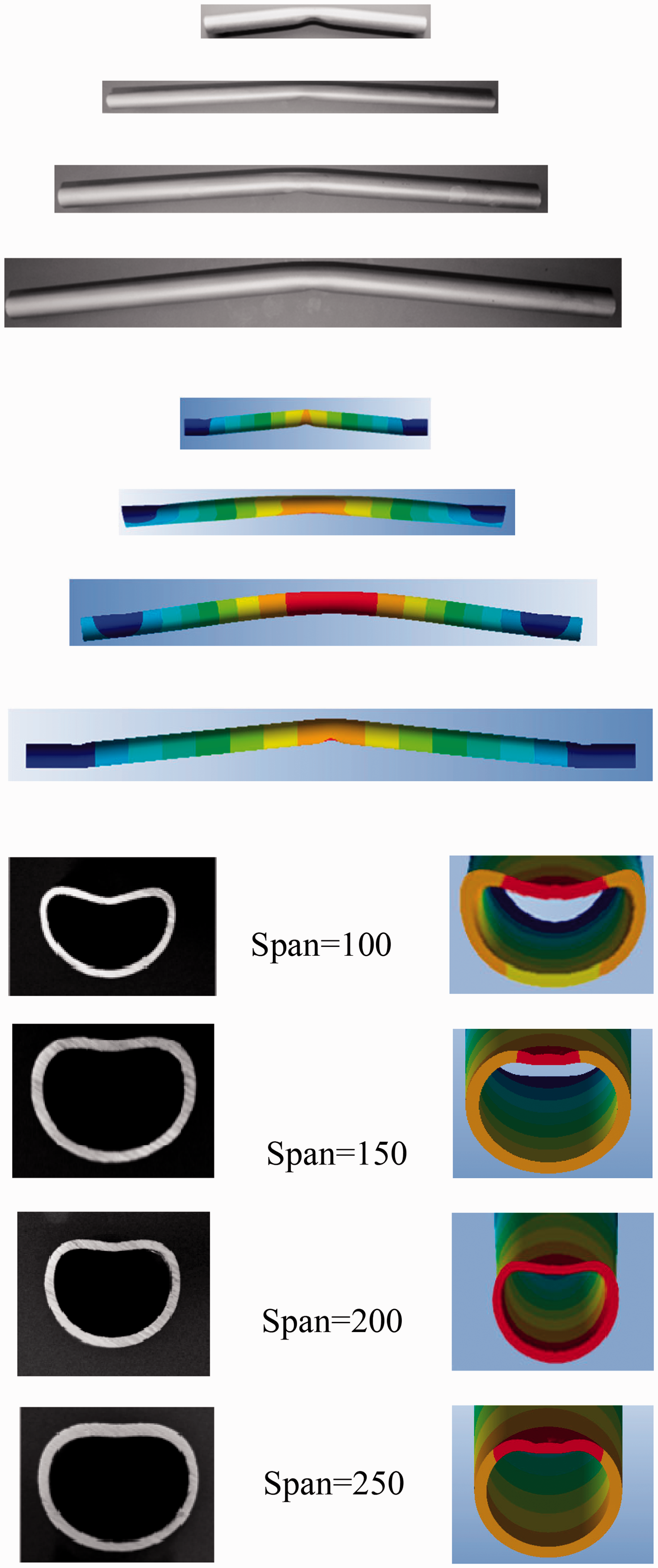
Different spans, the same ratio of D/t simulations and experiments.
Convergence diagram of meshing A1, B1, C1, and D1.
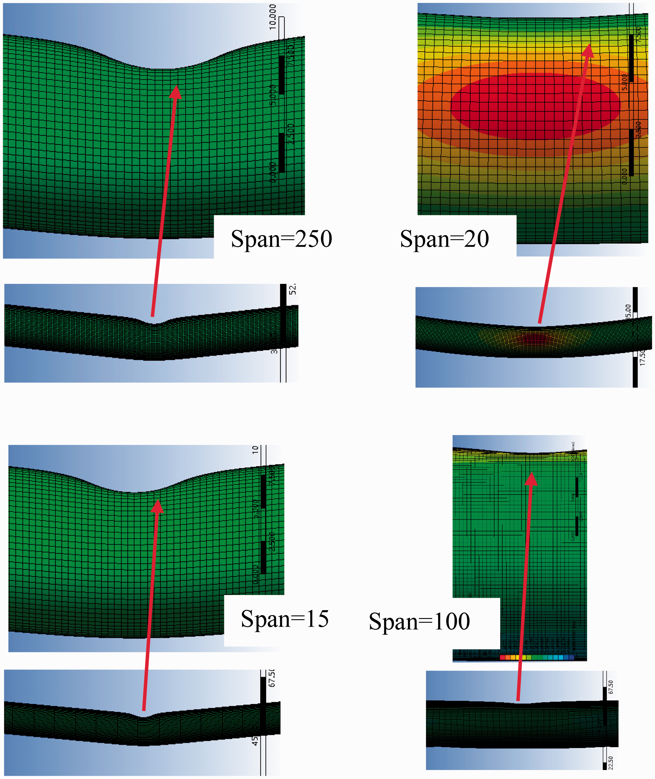
According to Figure 5, the simulation and experimental comparison chart through the ANSYS Workbench simulation results, it is found that the results obtained through the experiment are almost the same as the simulation results. At the same time, it was also found that the main forces of the four models A1, B1, C1, and D1 all curve out in the middle. It also shows that for different spans, the energy absorption of circular aluminum tubes with the same ratio of D/t is mainly concentrated in the middle part of the middle aluminum tube. According to the grid convergence (Figure 6), it can be seen from a macro view that when the aluminum tube is impacted by load, the grid in the maximum deformation area becomes more and more dense. From microscopic observation, it can be seen that when the span size is 200, the grid convergence is the largest. When the span is 100, the convergence of the grid is the smallest. At the same time, it reflects that the absorption performance of aluminum tube changes with the change of span size.
Different ratios of D/t, the same span simulation analysis
The following analysis will be based on different D/t ratios, with the same span size for simulation and comparison. The four models, D1, D2, D3, and D4, are extracted from Table 1 for analysis. The parameters are set first, then the boundary conditions and loads are applied, and finally, meshing is performed. D1, D2, D3, and D4’s meshing parameters are shown in Table 5. The set up was compared with the experiment. The comparison chart is shown in Figure 7.
D1, D2, D3, and D4 mesh parameter table.


Different D/t ratios, the same span size simulation and experimental comparison.
According to Figure 7, the D/t ratio is different, and the span size is the same as the simulation and experimental comparison chart. It can be seen that the maximum force of the D1, D2, D3, and D4 models is in the middle of the aluminum tube. It also shows that the maximum energy absorption site of the aluminum tube through the quasi-static three-point test is also here. Similarly, it has also been found that as the D/t increases, the energy absorption in the middle part of the aluminum tube becomes increasingly uneven and the stress becomes increasingly unbalanced. When the D/t ratio is 12.48, the energy absorption of the circular aluminum tube is the most uniform. From the simulation diagram, it can also be seen that as the ratio of D/t increases, the cross-sectional area of the main energy absorbing surface becomes narrower and narrower. It shows that energy absorption becomes more and more obvious. At the same time, combined with formula (2), with the increase of R, the D/t ratio increases and the flat width L increases, resulting in the deepening of the depression depth. From the simulation results and experiments in Figure 7, and the comparative analysis with the theory, the deformation and principle of the three are the same and conform with the real-world situation.
Comparative analysis of effect of different span and different D/t ratio on energy absorption of aluminum tubes
For the test and simulation analysis of the 6061-T4 circular aluminum tube material, the effect of the relationship between the length of the span dimension and the ratio of the D/t ratio on the energy absorption of the material during the research process is compared. In order to more clearly and intuitively obtain the relationship between the span of aluminum tube material, D/t ratio and energy absorption, take log10 for the actual value of energy absorption and the ratio of span/(D/t), respectively. The final result of the experiment is shown in Figure 8. Figure 9 is a graph of energy absorption versus Span/(D/t) ratios on the ANSYS workbench computer simulations.

Synthetic effects of span dimensions and D/t ratio on material energy absorption in experiments.

The effect of the span dimension and D/t ratio on the energy absorption of the material in the simulation.
According to Figure 8, it can be concluded that the energy absorption of the aluminum tube material decreases with increasing Span/(D/t) at the macroscopic level. At the same time, the span size and D/t ratio are both greater than 1, so when the span size is constant, the larger the D/t ratio, the smaller the Span/(D/t) ratio, and the greater energy absorption performance of the aluminum tube. When the D/t ratio is constant, the Span/(D/t) ratio will be larger, and the increase in span size will result in a decrease in the energy absorption performance of the aluminum tube, which is also in line with the actual application. At the microscopic scale, the energy absorption of the total data of the aluminum tube material in the test corresponds to an error of greater than 80% in the Span/(D/t) ratio. In about 72% of the data, it can be explained that the Span/(D/t) at this stage is particularly sensitive to the energy absorption performance. Therefore, when the energy absorption performance is judged by using Figure 8 and the ratio of the material span to the (D/t) ratio is selected, it can be seen more intuitively and more scientifically.
According to the simulation results shown in Figure 9, it can also be concluded that when the Span/(D/t) ratio increases, the energy absorption performance of the span sizes 100, 150, 200, and 250 mm will follow the decrease in the Span/(D/t) ratio. In the four simulation models, the energy absorption performance of their span size increases dramatically after one node. It can also be intuitively seen that as the D/t ratio decreases, the energy absorption increases. The reason for this is because this is in line with the several stages that aluminum pipes written in the previous chapter of this article will go through during the test.
Finally, by comparing the experimental results (Figure 8) with the simulation results (Figure 9), the energy absorption of the 6061-T4 circular aluminum tube is basically consistent with the Span/ (D/t) ratio. Similarly, when the spans are consistent, the D/t ratio decreases, while the aluminum tube absorbs energy increases and vice versa. This analysis method can be applied to similar material analysis methods. Simulation analysis is also found to predict similar characteristic trends of deformation behavior with the experiment, with a less than 3% average coefficient of variation.
Conclusion
Before the study of the 6061-T4 aluminum tube, the energy absorption failure of three-point quasi-static materials was theoretically analyzed. Then, a 6061-T4 round aluminum tube was experimentally studied. The energy absorption and failure of the 6061-T4 aluminum tube under three-point quasi-static state are analyzed. According to the same span size, different D/t ratios and different span sizes, the experimental analysis, simulation analysis, and theoretical verification of energy absorption and failure under the same D/t ratio are proposed. It can be found that the maximum stress of D1, D2, D3, and D4 models is in the middle of the aluminum tube. It is also shown that the maximum energy absorption part of the aluminum tube passing the quasi-static three-point test is also here. Similarly, it is also found that with the increase of D/t, the energy absorption in the middle part of the aluminum tube becomes more and more uneven and the stress becomes more and more unbalanced. When the ratio of D/t is 12.48, the energy absorption type of the circular empty aluminum tube is the most uniform. It can also be known from the simulation diagram that with an increase of D/t ratio, the cross-sectional area of its main energy absorbing surface becomes narrower and narrower. This shows that energy absorption is becoming more and more obvious. The simulation analysis also found that the predicted deformation behavior characteristic trend is similar to the test, and the average coefficient of variation is less than 3%. Finally, the simulation results are analyzed through experiments and discussed in combination with the theory. With the increase of the aluminum tube’s diameter, the flat width increases and the depression depth increases, and the greater the damage, the greater the capacity absorption, and the greater the SEA. However, when the D/t ratio gradually increases, the greater the displacement, the greater the PCF value generated. This analysis method can provide reference for research into similar materials in the future.
Footnotes
Handling Editor: José Correia
Declaration of conflicting interests
The author(s) declared no potential conflicts of interest with respect to the research, authorship, and/or publication of this article.
Funding
The author(s) disclosed receipt of the following financial support for the research, authorship, and/or publication of this article: This project is supported by the National Key Research and Development Program of China (grant no. 2018YFB2000502) and the National Science and Technology Major Project of the Ministry of Science and Technology of China (grant no. 2018ZX04002001), and the National Science and Technology Major Project (grant no. 2017-VII-0001-0094).