
Abstract
The water-meter shell has a complex-structured thin-walled cavity, and it can cause casting defects such as shrinkage and misrun. On the basis of structural analysis of a water-meter shell, a three-dimensional model and a finite element model of the water-meter shell were constructed using the SOLIDWORKS and ProCAST software as a modeling tool and a casting numerical simulation tool, respectively. Three processes associated with the bottom gating system without a riser, a step gating system with a preliminary riser, and a step gating system with an optimum riser were successively numerically simulated. The mold-filling sequence, temperature distribution, liquid-phase distribution during solidification, and shrinkage distribution of these three processes are discussed here. The numerical simulation results indicated that optimization of the casting process and the rational assembling of the riser led to the shrinkage volumes at the inlet position, regulating sleeve, and sealing ring of the water-meter shell decreasing from 0.68 to 0 cm3, 1.39 to 0.22 cm3, and 1.32 to 0.23 cm3, respectively. A comparison between model predictions and experimental measurements indicated that the castings produced by the optimized process had good surface quality and beautiful appearance, without casting defects, demonstrating that numerical simulation can be used as an effective tool for improving casting quality.
Keywords
Introduction
With the growing shortage of global energy and water resources, as well as the enforcement of legal metrology, ensuring the measurement precision of water meters has become imperative.1–3 The water-meter shell consists of a cavity containing water and a gear for measuring water flow, and high importance has been attached to its quality and performance. However, in actual production, due to its complex structure, the castings are prone to defects such as shrinkage and misrun. Furthermore, the water-meter shell should withstand pressures of 1.5 and 2.0 MPa for intervals exceeding 15 and 1 min, respectively. The current qualified rate of water-meter components is not sufficiently high, and in particular, the improvement of the qualification rate of the water-meter shell has significant economic benefits. 4
The trial-and-error method is mostly used in the traditional casting process design, and the design is improved on the basis of the experience of engineers and workers. In particular, in the process of developing and designing large castings and new products, it is necessary to repeatedly design the products and improve the design many times to meet the design requirements. Apart from resulting in a long design cycle and considerable material wastage, this process makes it difficult to guarantee the quality. Therefore, copper alloy castings designed and manufactured by the traditional method are expensive.
Since the 20th century, with the development of computer technology, numerical calculation methods, and heat transfer and related disciplines, developments in casting numerical simulation technology have been rapid, and the technology has been widely used. This technology can not only shorten the casting process design cycle and product trial cycle in the design and development of casting products but can also significantly reduce energy consumption and material loss.
The mold-filling process involving metal liquids was first studied by Hwang and Stoehr5,6 using fluid simulation software. Chen et al. 7 improved the two-dimensional (2D) message authentication codes algorithm to make it more versatile for studying liquid metal flows with various symmetries and the processing of the intersection surface of the flows. Thomas and Beckermann 8 improved a method used for geometric information analysis and the pressure iterative method, thereby reducing the computation time of numerical simulations. Lost foam casting was used by Hirt and Nichols 9 for numerical simulation studies. These authors incorporated a shrinkage defect prediction model in the commercial software FLOW-3D and successfully applied it to automotive castings. The gating system of a camshaft was studied by Jolly et al. 10 using numerical simulation techniques, and they showed that the porosity and the inclusion defects in the casting were caused by the excessive turbulence of the molten metal in the casting system. The pressure casting of thin-walled magnesium alloy parts was studied by Hu et al. 11 using casting numerical simulation technology, and the casting system was optimized and designed. Bansode et al. 12 used Taguchi’s method to investigate the effect of critical process parameters of investment casting on dimensional variations of thin-walled, complex geometrical stainless steel component. Prabhakar et al. 13 used the 2D computational fluid dynamics method to simulate the melt flow and solidification stage in the lead sand casting process. A numerical simulation approach based on the finite element casting software ProCAST has been developed by Sun et al. 14 Compared with insulation riser, shrinkage porosity proportion decreased from 23.10% to 17.01%, and the shrinkage cavity proportion decreased from 1.002% to 0.530%. Liu et al. 15 used the finite element model and ProCAST software to simulate and optimize the filling and solidification process of the casting, effectively eliminating the porosity and the shrinkage defects of the leaf spring bracket casting.
In 1965, the finite difference method was used by general electric engineers to perform numerical simulation studies on large thick-walled parts, and a predictable solidification model was developed.
16
The solid-phase method was first used by Henzel and Keverian
17
to predict the shrinkage defects of castings, and it was subsequently used for the numerical simulation of large steel castings; the steel castings produced on the basis of the simulation passed verification tests. In 1970s, the numerical simulation of the casting solidification process was studied in depth. On the basis of such a numerical simulation, a new prediction criterion for shrinkage defects, involving the expression
With the increasing demand for improving the quality and reducing the cost of products, the prediction of shrinkage defects in metal castings is of critical concern and a potential research area. In this study, in view of the complexity of the copper alloy water-meter shell structure, the filling and solidification processes in the fabrication of copper alloy water-meter shell castings were simulated using the numerical simulation software ProCAST for reducing the trial cost and design cycle time in the traditional trial and error method. Furthermore, the Niyama criterion was used for analyzing the formation of shrinkage defects in the solidification process. The use of casting numerical simulation technology helped not only to overcome the problem of not being able to observe changes in the molten metal in the mold cavity during the traditional casting process but also to optimize the casting process scheme, resulting in the fabrication of a higher-quality water-meter shell.
Development of casting model
Numerical simulations of castings are generally performed by assuming that the casting forming system shows geometrically limited dispersion. Changes in the flow field, temperature field, and stress field during the casting process were analyzed using numerical calculations, and the casting defect prediction method was combined with numerical simulations to predict the casting defect distribution. The copper alloy water-meter shell studied in this work is a water-meter component that protects the parts of the precision measuring instrument inside it. A 2D sectional view of the copper alloy water-meter shell is shown in Figure 1.

Cross section of copper alloy water-meter shell: 1, inlet; 2, outlet; 3, regulating sleeve; and 4, sealing ring.
The water-meter shell is a thin-walled cavity with a complex structure. The minimum and maximum wall thicknesses are 2.3 and 8.75 mm, respectively. The casting material used in this study was ZCuZn40Pb2, and its chemical composition is presented in Table 1. The liquidus and solidus temperatures of the casting material were 898°C and 887°C, respectively, and its specific heat capacity was 0.377 J/(kg⋅K); the quality was about 1.1 kg. Water-meter shell castings are required to have clear outlines and keep the porosity, cold insulation, misrun, and other defects at the lowest possible level. The structure is required to be compact and to have a certain strength and hardness so that it can withstand pressures of 1.5 and 2.0 MPa over intervals of 15 and 1 min, respectively.
Chemical composition of casting materials.

A complete water-meter model consists of a copper alloy water-meter shell casting, a gating system, and a sand core. For use in research, models of these water-meter components are established by SOLIDWORKS software. Three-dimensional (3D) models of a copper alloy water-meter shell and a sand core are shown in Figures 2 and 3, respectively. The casting was simulated using a virtual mold in ProCAST. The characteristics of the copper alloy water-meter shell casting were as follows: the grid size of the water-meter shell was set to 2 mm, the grid sizes of the casting system and sand core were set to 4 mm, and finer meshes were used in some sensitive areas. These values facilitated an accurate numerical simulation of the copper alloy water-meter shell and simplified the calculations. The casting is shown in Figure 4.

Three-dimensional model of a copper alloy water-meter shell.

Three-dimensional model of a sand core.

Meshing of the casting in ProCAST.
Structural optimization and simulation analysis
Bottom-injection-type no-riser design
The fabrication of a casting with a bottom-injection horn casting method without any riser was numerically simulated to determine the region where shrinkage defects were likely to be concentrated and the filling capability of the casting system, and a preliminary design of the gating system of the casting was developed. Further, the mold-filling capability was improved and casting defects were reduced. The 3D model of the bottom-injection-type no-riser design is shown in Figure 5.

Three-dimensional model of the bottom-injection-type no-riser design.
The mesh size of the casting was 2 mm, the total number of grids was 520,296, the casting temperature was 1000°C, the casting time was 3 s, and the initial mold temperature was 150°C. The temperature field of the filling process of the copper alloy water-meter shell, shown in Figure 6, was obtained from an analysis of numerical simulation results. The temperature field of the solidification process of the copper alloy water-meter shell is shown in Figure 7, and the distribution of shrinkage defects after solidification is shown in Figure 8.
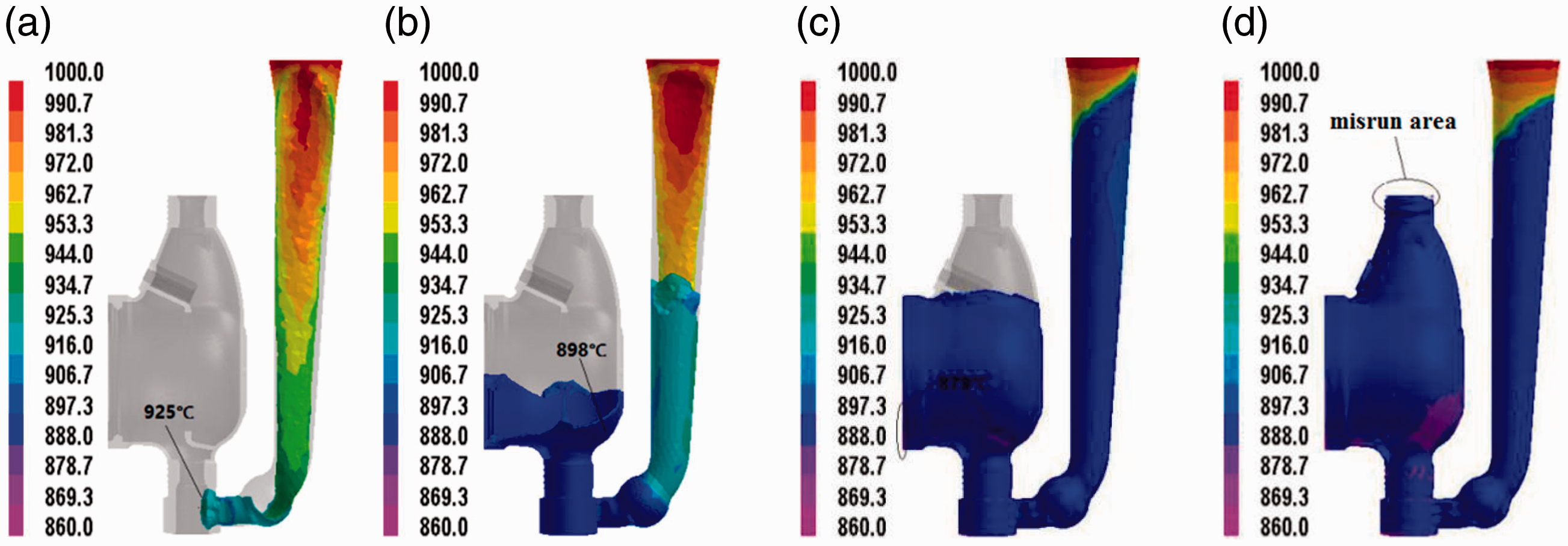
Temperature field of the filling process for the bottom-injection-type no-riser design: (a) t = 0.68 s, (b) t = 1.55 s, (c) t = 2.73 s, and (d) t = 3.00 s.
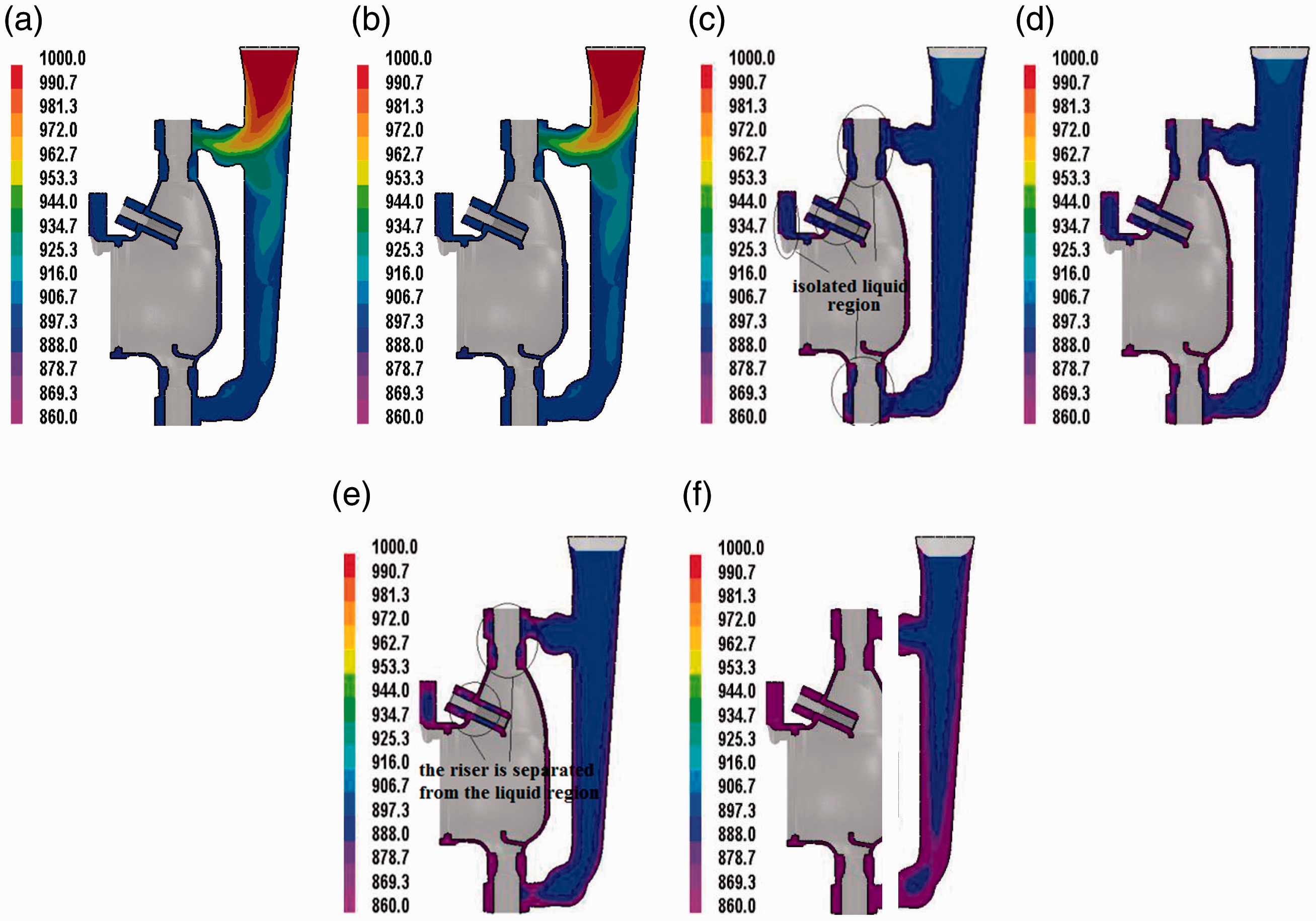
Temperature field of the solidification process for the bottom-injection-type no-riser design: (a) t = 3.00 s, (b) t = 3.77 s, (c) t = 4.88 s, (d) t = 6.10 s, (e) t = 7.59 s, and (f) t = 11.84 s.

Distribution of shrinkage defects in the bottom-injection-type no-riser design.
In Figure 6, in the bottom-injection-type no-riser design, the molten metal rises smoothly during the filling process without splashing, and the gas in the cavity can be smoothly discharged, so that the occurrence of defects such as pores can be effectively avoided. However, because of the chilling effect of the metal mold, the thin-walled region of the casting easily solidifies prematurely. This leads to the supplementary molten metal being blocked, resulting in the formation of misrun defects. Therefore, it is necessary to include a supplementary runner in the upper part of the water meter to compensate for the insufficient filling capability of the bottom-injection-type no-riser design.
In Figure 7, the core cavity wall of the water-meter shell begins to solidify first, for this wall is the thinnest. As the solidification progresses, four isolated liquid regions are gradually formed. These are the locations where shrinkage defects of the water-meter shell are concentrated. From an overall perspective of the entire solidification process, the heat distribution of the bottom-injection type is not uniform, which is detrimental to the sequential solidification of the casting. An analysis of the casting temperature field revealed the presence of a large number of hot spots at the inlet and outlet of the casting, at the sealing ring, and at the adjusting sleeve. It is evident from Figure 8 that the largest shrinkage defect areas of the casting were at the adjusting sleeve and the sealing ring, consistent with the location of the isolated liquid region in the liquid-phase distribution diagram. These results show that these shrinkage defects were generated because of the large wall thickness, which resulted in a long solidification time. By contrast, the wall in the adjacent part was thinner, leading to premature solidification, and the supplementary runner was broken to form an isolated liquid region.
Step-type trial-riser design
On the basis of an analysis of the numerical simulation results for the bottom-injection-type no-riser design, the casting was supplemented with a riser, and the step casting design was adopted to enhance the filling capability. With these steps, misrun defects were effectively avoided. The 3D model of the step-type trial-riser design is shown in Figure 9.

Three-dimensional model of the step-type trial-riser design.
The mesh size of the casting was 2 mm, the total number of grids was 551,932, the casting temperature was 1000°C, the casting time was 3 s, and the initial mold temperature was 150°C. The temperature field of the filling process of the copper alloy water-meter shell, shown in Figure 10, was obtained from an analysis of numerical simulation results; the temperature field of the solidification process of the copper alloy water-meter shell is shown in Figure 11, and the distribution of shrinkage defects after solidification is shown in Figure 12.

Temperature field distribution of the filling process for the step-type trial-riser design: (a) t = 0.85 s, (b) t = 2.14 s, (c) t = 2.52 s, and (d) t = 3.00 s.

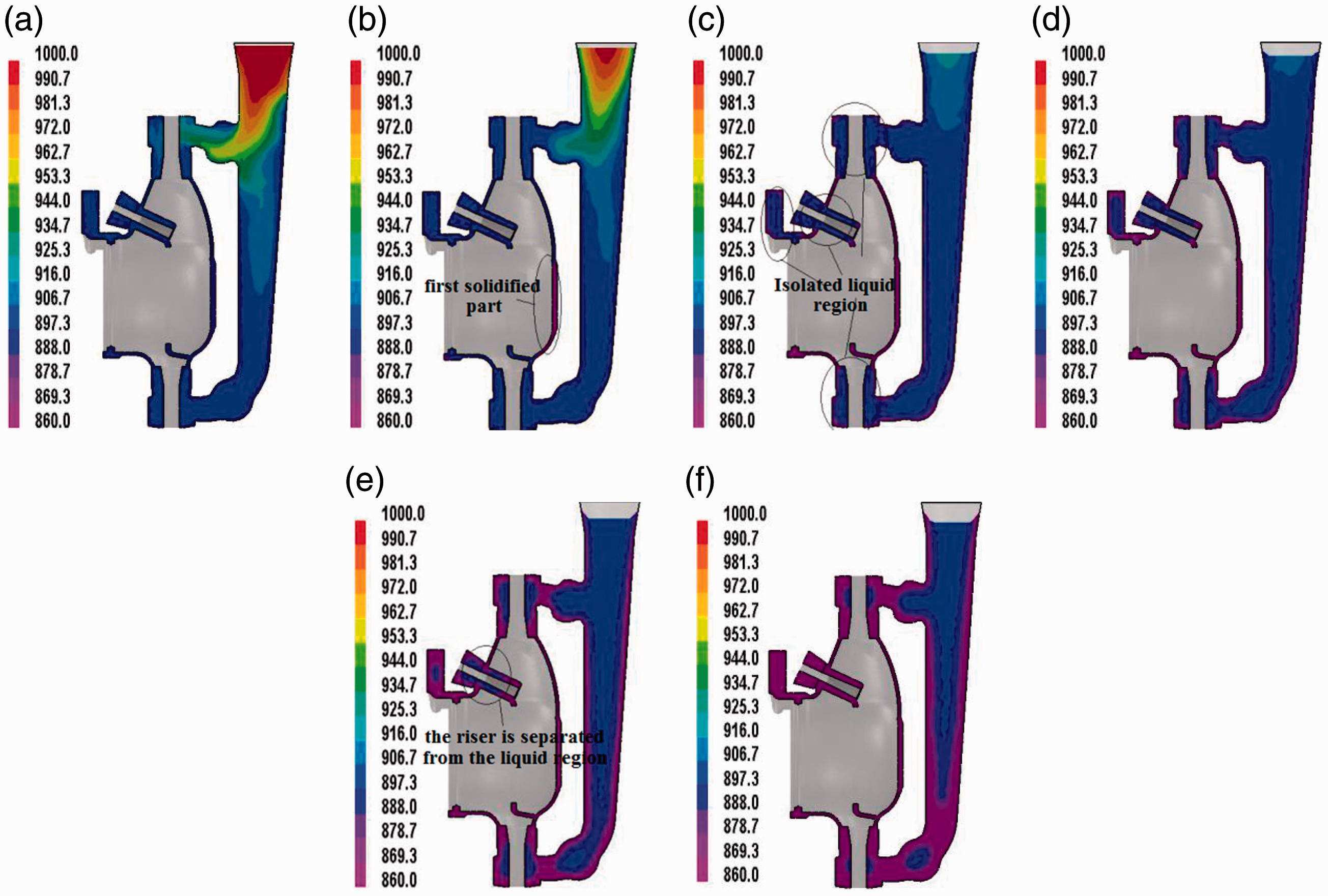
Temperature field of the solidification process for the step-type trial-riser design: (a) t =3.00 s, (b) t = 4.11 s, (c) t = 6.84 s, (d) t = 7.38 s, (e) t = 9.20 s, and (f) t = 13.16 s.

Distribution of shrinkage defects in the step-type trial-riser design.
It is clear from Figure 10 that the improvement of the gating system and the addition of a supplementary runner solved the problem of insufficient filling capability of the bottom-injection-type no-riser design. When the filling capability is affected by a temperature decrease, the molten metal entering from the supplementary runner opened in the upper part can merge with the molten metal entering from the bottom runner. Consequently, a temperature gradient is formed such that the temperature in the middle of the casting is the lowest, and the temperature increases upward and downward, which is favorable for the sequential solidification of the casting.
A comparison and an analysis of the temperature fields of the solidification process, shown in Figures 7 and 11, reveal that in the step casting design, the position of the isolated liquid region of the casting remained unchanged despite the addition of the supplementary runner; the addition of the riser significantly enhanced the feeding effect of the isolated liquid region. Figure 12 shows that through the addition of risers, shrinkage defects in the castings can be transferred, indicating that the choice of the riser position strongly influences the feeding of the casting; the shrinkage defect appears to be significantly smaller, but is not completely transferred, which indicates that the structure and size of the riser are inappropriate and insufficient, respectively. Thus, the full feeding of the casting and the complete transfer of the shrinkage defects were not achieved with the step-type trial-riser design.
Step-type improved-riser design
On the basis of an analysis of the numerical simulation results for the filling and solidification processes for the step-type trial-riser design and due to the satisfactory effect observed for the step casting design, the casting method was not changed and the design of the riser was optimized. Since the inlet and outlet of the water-meter shell and the adjusting sleeve had cylindrical structures, the elimination of shrinkage defects could not be perceived only by increasing the riser diameter and height. For the complete elimination of shrinkage defects, the wall thickness was gradually increased toward the riser on the part of the casting near the riser, and a wedge-shaped wall was formed in the casting structure to achieve a temperature gradient that gradually increased toward the riser. The temperature gradient considerably increased the effective feeding distance of the riser.
A thickness compensation design for the inlet and outlet and a regulating adjustment were used in this study, and they are shown in Figure 13. The improved riser, shown in Figure 13(a), had the following features: the compensation thickness at the inlet and the outlet of the riser was 3 mm, the size of the annular riser was 33 mm, the diameter of the inner circle was 14 mm, and the height was 20 mm. Furthermore, the improved regulating adjustment part, shown in Figure 13(b), had the following features: the compensation thickness at the regulating adjustment of the riser was 1.5 mm, the riser structure was changed to a trapezoidal step, the diameter of the large end was 11 mm, the diameter of the small end was 9 mm, the diameter of the inner circle was 4.5 mm, and the height was 15 mm.

Optimization of the riser: (a) inlet and outlet of the riser and (b) regulating adjustment part.
The mesh size of the numerical model was 2 mm, the total number of meshes was 571,551, the filling time was 3 s, and the solidification time was 22.76 s. The temperature field of the solidification process of the copper alloy water-meter shell with a step-type improved-riser design was obtained from an analysis of numerical simulation results, and it is shown in Figure 14; the distribution of shrinkage defects after solidification is shown in Figure 15.
Temperature field of the solidification process for the step-type improved-riser design: (a) t = 3.00 s, (b) t = 3.70 s, (c) t = 6.09 s, (d) t = 7.27 s, (e) t = 9.63 s, and (f) t = 11.63 s.

Distribution of shrinkage defects in the step-type improved-riser design.
It is evident from Figure 14 that the problem of the isolated liquid phase at the sealing ring, inlet, outlet, and regulating adjustment can be considerably improved using an improved riser. Figure 14(a) shows the temperature field of the casting at the instant filling was completed. The temperature of most parts of the casting is near the liquidus, and the temperature of the thinner cavity wall is below the liquidus. As shown in Figure 14(b), at 3.70 s, the cavity began solidifying, and the solidification sequence started from the bottom and progressed upward. At this time, the temperature of all parts except the sealing ring, inlet, outlet, and regulating adjustment was below the liquidus. In Figure 14(c), at 6.09 s, the thinner cavity wall had solidified, and the unsolidified part of the casting was separated into three portions, namely, the sealing ring, adjusting sleeve, and inlet and outlet of the gating system. The solidification at the sealing ring was completed at 7.27 s (Figure 14(d)), and at 9.63 s, the isolated liquid region at the regulating adjustment was divided into two parts (Figure 14(e)). However, the size of the liquid-phase region in the regulating adjustment was smaller than that in the case of the trial riser. For the step-type improved-riser design, the liquid phases at the inlet and outlet were disconnected from the gating system, forming isolated liquid phases. During the solidification process, the liquid phases at the two locations slowly moved toward the risers and finally disappeared at the risers.
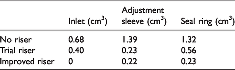
It is clear from Figure 15 that with the improved riser design, shrinkage defects were completely eliminated at the inlet and the outlet of the casting and were present in small numbers at the regulating adjustment and sealing ring. The distribution of shrinkage defects in different processes and different parts is shown in Figure 16. The volume pairs of shrinkage defects in different processes and different parts are presented in Table 2.

Comparison of the distribution of shrinkage defects between different processes and different parts.
Volume comparison of shrinkage defects between different processes and different parts.
Experiment
Casting process
Sand core production
Since the water-meter shell is thin-walled and encloses a cavity, it is necessary to fabricate a sand core. The sand core is used to form the inner cavity, holes, and some specially shaped pits on the casting. During casting, most of the sand core is covered by the molten metal and is subjected to heat transfer and influenced by the flow of the high-temperature metal liquid. Therefore, the quality of the sand core directly determines the quality of the casting. The sand-core-making equipment used in this experiment was the DL-400-B automatic double-head core shooting machine, and it is shown in Figure 17. The materials used for preparing the sand core in this study and their amounts were as follows: silicon (50 kg), a curing agent (180 mL), a resin binder (800 mL), and an additive (30 mL); the sand core prepared is shown in Figure 18.

DL-400-B automatic double-head core shooting machine.

Sand core prepared in this study.
Metal smelting
Metal smelting is a complex physicochemical process that involves the chemical interaction between the metallic elements and its interaction with gases, lining materials, and the like. Since copper alloy is easily oxidized, it is the decisive factor to obtain qualified metal liquid in strict accordance with the process. The main steps in the smelting process are copper → charcoal → melting → lead + zinc → slagging-off → heating and spraying fire → addition of P-Cu + Al → tapping and casting. The smelting furnace DL-GYT-III was used in this study, and it is shown in Figure 19.

Smelting furnace DL-GYT-III.
Coating on the mold
The metal mold is made of forged red copper. The mold used for obtaining a casting of the copper alloy water-meter housing requires a coating on its surface for each casting. The coating method used in this study was soaking the mold in graphite–water mixture. Graphite is a heat-resistant substance that is suitable for separating the high-temperature metal liquid from the mold, so that the life of the mold can be effectively extended. Moreover, graphite particles are very small, and therefore, the fluidity of the metal liquid can be increased to some extent, which is convenient for filling the mold.
Casting
The quality of the copper alloy water-meter shell mostly depends on the quality of the casting. In this study, the pouring temperature was 1000°C, the casting time was 3 s, and the initial mold temperature was 150°C; the mold was tilted by 60° during the casting process and rotated at a constant speed so that the gas in the casting could be effectively released and the flow rate of the molten metal could be lowered for further improving the quality of the casting. The casting equipment used in the experiment was the gravity casting machine SD-450-B, shown in Figure 20.

Gravity casting machine.
Post-treatment of casting
The casting of the copper alloy water-meter shell was small. Therefore, after the casting was cooled, the casting system was removed by manual tapping, and the riser was cut off by a sawing machine to obtain the final casting for subsequent machining.
Comparative analysis of casting quality
On the basis of the results of the optimization of structural and casting process parameters, the production of the copper alloy water-meter shell before and after optimization was studied in depth. A comparison of the casting surface quality is shown in Figure 21, and a cross-sectional comparison of the castings is shown in Figure 22.

Comparison of surface quality of castings: (a) before optimization and (b) after optimization.

Comparison of surface quality of castings: (a) before optimization and (b) after optimization.
In Figure 21(a), before optimization, there were many gas porosities and shrinkage defects at the water outlet of the casting, and the surface quality at the water outlet was poor. As Figure 21(b) shows, after optimization, the surface quality of the casting was good, and there were no defects such as misrun, cold separation, or pores.
In Figure 22(a), the cross section of the water-meter shell before optimization shows shrinkage defects and gas porosities of different sizes at the inlet and the outlet of the casting and the adjusting sleeve, which would seriously affect the quality and performance of the casting. The cross section of the casting after the optimization of the casting structure and casting process parameters is shown in Figure 22(b). The section quality of the casting is good, without shrinkage, porosity, or any other defect. Furthermore, the optimized casting was cut longitudinally to examine a longitudinal section for defects; the longitudinal section is shown in Figure 23. There is no shrinkage cavity, porosity, or any other defect in the longitudinal section, and the quality is good.

Longitudinal section of the casting.
Conclusion
The copper alloy water-meter shell was selected as the research object in this study. The casting process parameters were numerically simulated and optimized for eliminating defects such as shrinkage and misrun. From numerical simulations, experimental comparison, and an analysis of the casting process, the following conclusions were drawn:
On the basis of an analysis of the structure of the water-meter shell, a preliminary design of the gating system was developed. The step gating system was adopted, and the ingates were set at the inlet and outlet of the casting. A preliminary design of the riser was made at the positions of the inlet, outlet, sealing ring, and regulating sleeve of the water-meter shell. Subsequently, the 3D model and finite element model of the casting were developed. On the basis of a numerical simulation analysis of the casting structure and the optimization of the riser, the shrinkage volume at the position of the inlet, regulating sleeve, and sealing ring of the water-meter shell was reduced from 0.68 to 0 cm3, 1.39 to 0.22 cm3, and 1.32 to 0.23 cm3, respectively, indicating significant reductions. Experimental comparison between and an analysis of the water-meter shell casting produced using the optimized process parameters and that produced using nonoptimized process parameters indicated that the optimized copper alloy water-meter shell exhibited a beautiful appearance and had good surface quality, without macrodefects such as cracks, cold shuts, and misrun. The microstructure of the cross section of the casting was compact and without microdefects such as shrinkage or porosity. This result shows that the optimized process parameters obtained in this study can effectively improve the quality of castings and increase productivity by minimizing the number of rejections, thereby reducing production cost.
Footnotes
Handling Editor: James Baldwin
Declaration of conflicting interests
The author(s) declared no potential conflicts of interest with respect to the research, authorship, and/or publication of this article.
Funding
The author(s) disclosed receipt of the following financial support for the research, authorship, and/or publication of this article: This project was supported by the National Natural Science Foundation of China (Grant Nos 51875106 and 51975123) and Fuzhou Science and Technology Plan Project (Grant No. 2019-G-42).