
Abstract
Applying a semi-recursive multibody approach enables the solution of the equations of motion of a complex system in real time. This makes it possible to conduct human-in-loop simulations and analyse the user experience. The idea of recognizing the user experience to produce more efficient, competitive, and user-friendly products has been limited thus far to the field of information technology and the development of light physical products. This study introduces a simulation modelling procedure for a complex forklift mast system that can be used to help analyse the user experience. A multibody forklift model is introduced that includes the electric motors, a pump, a freelift, a mainlift and tilt cylinders, actuators, pulley and chain mechanisms, contacts, and tyres. The viscoelastic behaviour of the chain during longitudinal and transverse movement is simulated using a discrete model approach. Triplex mast speeds and hydraulic system efficiencies across working cycles are used to verify the performance of the introduced real-time simulation model against measurements taken from an equivalent reference forklift. To better evaluate the developed model, experienced and inexperienced forklift drivers were asked to drive an updated simulator and provide feedback. User experience inputs that can be made available early on in development using this new modelling approach will permit experts to evaluate and design more efficient complex mechanical systems.
Keywords
Introduction: a shift to a user experience–based product development approach for mobile machinery
Smart product development and product service systems emphasize design for mass personalization (DFMP), which is based on the identification and implementation of the user experience (UX) in the early phases of research and development (R&D).1,2 The identification of the UX through the early interaction of users and products enables companies to design competitively attractive, adaptive, and scalable products and services for an appealing UX and increased customer satisfaction.2,3 Previous studies have indicated that a UX-based product development approach for mass personalization has been applied to the development of information technology (IT) services and light and small products.1,4,5 Complex mechanical systems have not been studied in the DFMP context, because of the difficulty of making physical prototypes available to potential users.
Many researchers have employed dynamic simulation models to describe the basic design and operation of machines.6–14 Conversely, the involvement of the UX in the early phase of product development through simulation demands the description and faster computation for all sub-components and mechanisms of the mechanical systems in a realistic working environment. The multibody system (MBS) semi-recursive approach enables solution of the equations of motion of complex systems in real time. 15 Physics-based real-time simulation multibody models can be seen as accurate representations of the machines being modelled. Real-time simulation methods enable users to control, test, analyse and validate a new physical product with minimum cost, time and effort. Users can report on the UX based on real-time simulation of the complex machines in typical working environments and hence better evaluate machine performance. This article describes the real-time simulation of a forklift.
The field performance, efficiency and service life of the forklift truck are closely related to the mast lifting mechanism, because it is responsible for the loading, unloading and transporting.16,17 Accordingly, most forklift failures are associated with their mast systems. 18 The triplex mast system addressed in this article is a complex mechanical system. It involves the MBS modelling of the forklift, hydraulic system, contacts, tyres and pulley, and chain mechanism. The realistic simulation of the chain reveals its viscoelastic responses during longitudinal and transverse movements. Kaminski used the rigid finite element method based on the Kruszewski assumptions for the modelling of chains. The modelling method requires various properties of repeating elements such as density, length, diameter, Young’s modulus, normal damping and shear damping. 19 In this study, however, a simplified chain model known as discrete model is employed. Discrete chain model includes spiral springs that connect repeating units. The bending theory and geometrical relationships between the repeating units were selected such that visual performance chain resamples behaviour of real structure. 20
Few studies have dealt with combining the semi-recursive approach, hydraulic actuators, LuGre friction and tyre models in the real-time simulation of rigid and flexible MBSs.21–24 The real-time simulation of the pulley and chain mechanism has not yet been studied with hydraulics, contacts and tyres in the framework of MBS dynamics. Conventional forklift simulation methods also focus on the development of the mast design system and do not consider the pulley and chain mechanisms or the realistic UX for the working cycles of the truck in the presence of the lifting loads.6–14 The real-time multibody forklift model have been studied without discussing the hydraulics, pulley and chain mechanism and mast design system. 25
The objective of this study is to combine semi-recursive approach, hydraulic actuators, tyres, and pulley and chain models with associated contacts in the real-time simulation model of a 3-W counterbalance 2.0-t EVOLT48 electric forklift for a realistic UX. The movement pattern of the lifting cylinders is modelled after the reference forklift working cycles. To evaluate the result, users were asked to execute a number of forklift working cycles on the simulator via a control interface and to report on the real-time multibody simulation UX. The effect of the lifting loads on triplex mast speeds represents the relationship between user feelings and simulation results. The performance of forklift model simulation is compared to the system efficiency of the hydraulics with the reference forklift in real time.
Combining multibody formulations to improve the UX
The semi-recursive approach
This study employs the semi-recursive approach to express the equations of motion for an open loop constrained mechanical system. The equations of motion of the system are described using the velocity transformation matrix that accounts for the position of each joint. 15
Kinematics
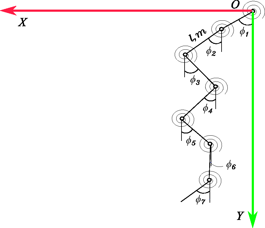
This study utilizes the reference coordinate system shown in Figure 1. As can be seen,

Two bodies in the reference coordinate system.
The position

The rotation

Equations of motion
The equations of motion can be derived using the principle of virtual power and can be expressed as
15


Discrete chain model
Figure 2 describes the chain model used in the study. The chains of the triplex mast system are modelled using the discrete model.
20
In this approach, the chain is assumed to be made of

The repeating units of mass
Modelling the hydraulic actuators
This section briefly reports the modelling approaches of the actuators, valves and cylinders used in the forklift.
Pressure estimation
This study uses the lump fluid theory to compute pressures within the hydraulic circuit.
27
This theory assumes that the hydraulic circuit can be divided into volumes with equally distributed pressures. The pressure in each volume can be expressed using a differential equation as follows


Valves
In the simulation, the hydraulic cylinder movements are controlled by the opening and closing of valves. The valves are modelled using a semi-empiric method according to which the flow rate


Cylinders
Figure 3 describes the cylinder model. The hydraulic cylinder is modelled using the dimensions and pressures of the cylinder.
29
The flow rates


Cylinder model of the hydraulic system.
Tyre and contact models
The LuGre model is used to describe the friction force between the tyres and ground. It offers higher computational efficiency than finite element methods, making it suitable for real-time simulation applications.30,31 The LuGre model can be described by considering the tyre and ground as rigid bodies. In practice, tyre model consists of discs as shown in Figure 4(a). The tyres are described with inertia and tyre profile with respect to wheel hub. In the Figure 4(a),


LuGre friction model between tyre and the ground (a) tyre disc model and (b) tyre and ground contact model at microscopic level. Upper bristles are deflected by the lower rigid bristles.
Developing a test real-time simulation model based on the UX
This section introduces the forklift triplex mast model including the pulley and chain mechanism and hydraulics. Hydraulic system efficiency will be used to study the input motor power with reference to the output power of the triplex mast system as the real-time simulation application.
Forklift model and pulley and chain mechanisms
The dimensions and lifting capacity of the system used in this study are presented in Figure 5. In the figure,

The bodies with the corresponding local coordinate systems and joint coordinates in the multibody system of the forklift. Red, green and blue markers in the local coordinate system of each body indicate the
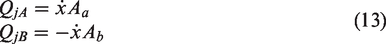
The relative joint velocity vector
Semi-recursive multibody matrix of the 3-W counterbalance 2.0-t EVOLT48 electric forklift.

The chains and pulleys are responsible for lifting and holding loads between 0 and 2000 kg during loading and unloading operations. Figure 6(a) and (b) describes the topology of the pulley and chain mechanisms in the freelift and mainlift portions that are used to build the multibody triplex mast real-time simulation. The triplex mast unit requires one pulley and chain mechanism for freelift extension and retraction and two pulley and chain mechanisms for mainlift extension and retraction. The topology of the pulley and chain mechanism in Figure 6(a) corresponds to freelift, and the pulley and chain mechanism in Figure 6(b) relates to mainlift. As can be seen in the freelift portion, one end of the chain is connected to the body

Topology of pulley and chain mechanisms in the multibody triplex mast unit of the forklift simulation model: (a) freelift portion of triplex mast and (b) mainlift portion of triplex mast.
Mass per unit (kg) and number of repeating units in the freelift and right

DOF: degree of freedom.
Hydraulic subsystem of the triplex mast
Electric motor and pump
The pump of the hydraulic circuit is driven by an electric motor. The following differential equation is used in this study to relate the torque and angular velocity of the motor


Tilt operation
Figure 7(a) and (b) shows the hydraulic circuit associated with tilt operation. Figure 7(a) shows the hydraulic circuit that is used to control the mast tilt forward and backward movements. A 4/3 directional valve enables the movements of the right tilt

The mast tilt operation and tilt hydraulic circuit comprising a 4/3 directional control valve and two double acting cylinders: (a) tilt forward and tilt backward operation and (b) tilt hydraulic circuit.
Loading and unloading circuits
The working pressure of the circuit is determined from the vertical load on the lifting cylinders. The load 


The hydraulic circuits of the mast loading and unloading operations.
Figure 7 illustrates the hydraulic circuit for loading and unloading operations. A counterbalance (CB) valve is used to lift the loads vertically on the mainlift and freelift cylinders and prevent rapid downward movements due to gravitational forces. The lifting portion of the circuit is connected to the pump 
In order to unload triplex mast, pressure at the point 

Movement pattern of freelift and mainlift cylinders
The simulated triplex mast of the forklift has to lift loads of 0–2000 kg at different heights of the 

The extension and retraction of mainlift and freelift cylinders during the loading and unloading operations: (a) minimum freelift and mainlift strokes, (b) maximum freelift and minimum mainlift strokes and (c) maximum freelift and mainlift strokes.
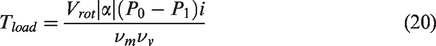
Efficiency of the hydraulic system
The efficiency of the hydraulic system 
Software implementation and visual UX in the real-time simulation model
The computer environment solves the equations of motion of the MBS containing hydraulics, discrete chain model, tyres and contact models as well as user control in real time. This is conducted using monolithic solution scheme with fourth-order Runge–Kutta method at a time step of 0.0012 s. The visualization of multibody model and environment is developed in 3D to provide real world UX to the users. The visual presentation of real-time forklift model and its environment can be seen in the Figure 10. The forklift model is simulated in C++ environment (compiler: Microsoft Visual studio, version 14.1) in real time. The details of the operating system Windows 7 are processor Intel Core i7 3.60 GHz, random access memory 64.0 GB, graphic memory 36,809 MB and display adapter Nvidia Quadro M2000.
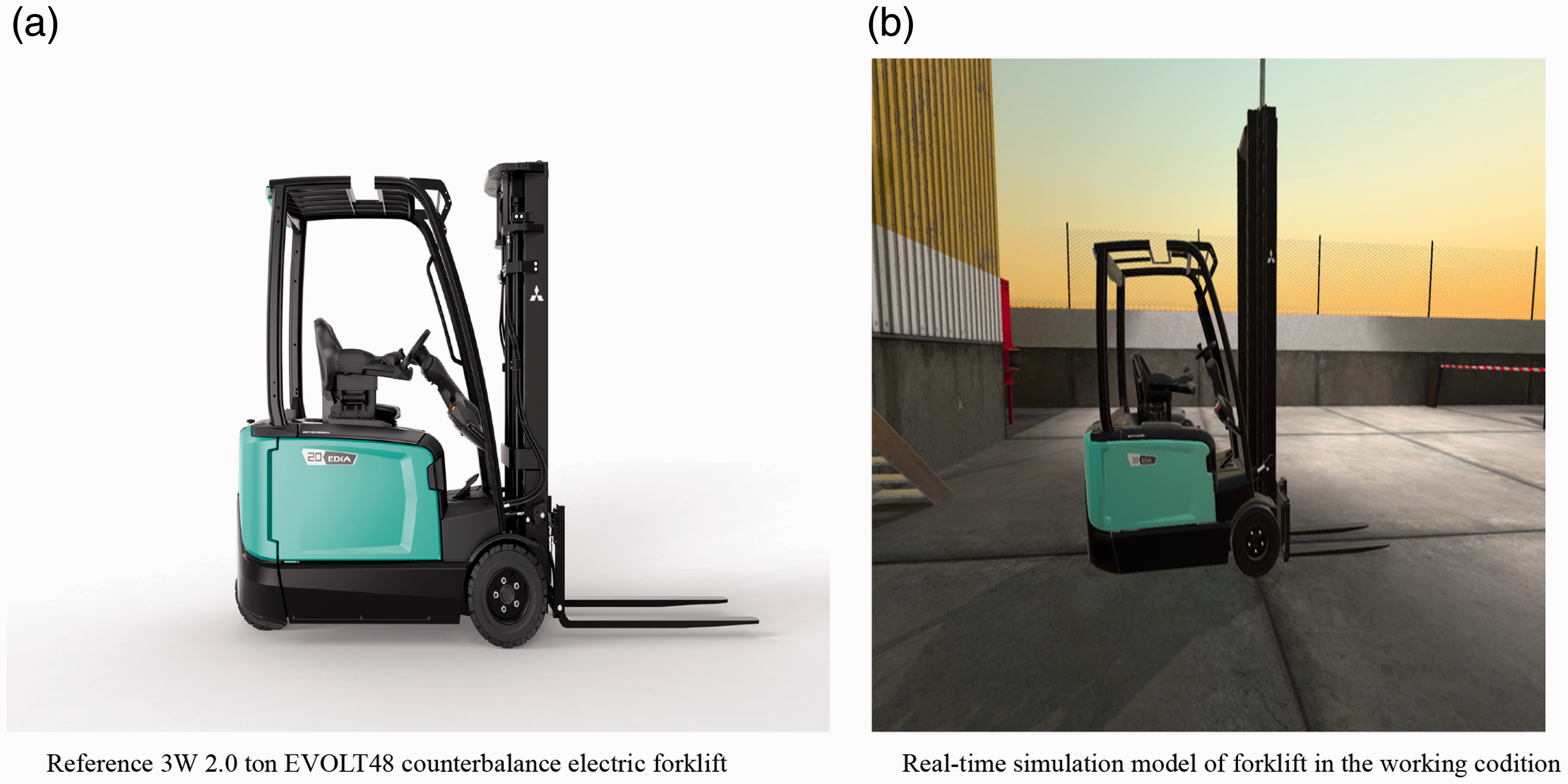
Visual UX of the real-time forklift simulation model: (a) reference 3-W counterbalance 2.0-t EVOLT48 electric forklift and (b) real-time simulation model of forklift in the working condition.
Hardware solution for the realistic UX in real-time forklift simulation
Users communicate with the dynamic real-time simulation model via a user interface system (I/O) of analogue and digital signals. 35 The loading and unloading operations of the physical forklifts are controlled via an analogue input, and the tilt forward and backward functions are operated with another analogue input. Dual axis industrial grade joystick controls the lift and tilt operation of mast in the simulation. The users can operate the simulation model using accelerator and brake pedals, and steering wheels. The used pedals are 2-way analogue type to give feelings of actual forklift driving to the users. Pedals and joysticks are connected to the simulator machine via to National Instrument I/O Device interface. These pedals and joysticks do not provide any artificial feedback to the users. Gaming-grade Fanatec steering wheel with no auto centring option is used for the steering operation. The steering wheel was attached to the simulator machine via USB connection. Moreover, the artificial sounds are added for driving motors, steering motor, and lift and tilt cylinders to enable auditory UX in the real-time simulation model. Users can operate the forklift in virtual environment and express satisfaction or dissatisfaction with the function, capability and behaviour of the forklift.
Mast wobbling and UX in lifting loads
In the real forklift, the triplex mast wobbles at maximum and minimum lifting heights.
25
The mast wobbles in a forklift due to mast system, transverse movements of chain mechanism and the flexibility of tyre rubber. In this study, the UX for this mast wobbling phenomenon is modelled with an end damper spring, discrete chain model, and the LuGre friction force between the tyre and ground model to generate realistic system behaviour during lifting loads in real-time simulation.36–39 The end damper spring is defined between the 
Normalized LuGre tyre spring coefficients and damping coefficients of multibody forklift model.

The 800, 1600 and 2000 kg load pallets are described as separate rigid bodies. The floating joint is described between the load pallets and the ground. It ensures free movement of the load pallets in the simulation environment. The description of collision model between load pallets and tyre models, and the collision between the triplex mast and the load pallets give feelings of loading and unloading working cycles to the users in the simulation environment. It also replicates the real-time simulation model UX to the reference forklift movement in real working conditions.
Model verification and UX evaluation
This study employs the mast up and mast down speeds to verify the accuracy and UX of the simulation model. In practice, this is carried out by comparing the simulated results against measurements of the reference forklift for 0, 800, 1600 and 2000 kg lifting loads.
Figure 11 gives the mast speed time graphs for the simulated triplex and the reference masts during loading and unloading operations. In Figure 11(a), the first two peaks of the speed time graph from 1.7 to 15 s represent the loading operation. In the same figure, the mast down operation is shown in the interval from 17 to 30 s. Oscillations or mast wobbling can be seen at the end of loading and unloading operations in reference and simulation forklifts. The loading operation is divided into freelift and mainlift extension zones, the first and second peaks in Figure 11(a), respectively. In unloading operation, the first peak of the speed time graph relates to the mainlift zone and the second relates to freelift. Similarly, the loading and unloading operations are illustrated in the simulated and reference forklifts for 800, 1600 and 2000 kg lifting loads. The fluctuations at the end of each lifting zone represent mast wobbling.

The mast up and mast down speeds of a simulated forklift against the reference forklift: (a) reference mast speed at 0 kg, (b) simulation mast speed at 0 kg, (c) reference mast speed at 800 kg, (d) simulation mast speed at 800 kg, (e) reference mast speed at 1600 kg, (f) simulation mast speed at 1600 kg, (g) reference mast speed at 2000 kg and (h) simulation mast speed at 2000 kg.
The simulated mast up and down speeds in Figure 11(b) are similar to those of the reference speeds at 0 kg. In this case, the simulated triplex mast indicates less mast wobbling compared to the reference lift speeds. Figure 11(c) and (d) illustrates the 800 kg lifting case. Nevertheless, the simulated mast up speed during the freelift and mainlift extensions is in agreement with the reference speeds. The maximum mast up and mast down speeds remain the same in both cases for 1600 and 2000 kg lifting loads. The UX of mast wobbling is quite evident in the graph for these lifting cases at the extreme positions of the triplex mast.
Real-time performance of hydraulic cylinders
The introduced simulation model is used to analyse the performance of the hydraulic system with 0, 800, 1600 and 2000 kg lifting loads in comparison to a physical forklift. As discussed in equation (28), the hydraulic system efficiency measurements account for the input motor power and output power in terms of the average mast speeds and lifting loads. Figure 12(a) and (b) illustrates the efficiency of the full hydraulic systems of the MBS simulation and the reference forklifts during the freelift and mainlift cylinder movement zones, respectively. The cyan-coloured line in Figure 12 relates to the simulated forklift, whereas the orange line describes the reference forklift. The blue and the green squares on the lines report the efficiency of the hydraulic systems at 0, 800, 1600 and 2000 kg lifting loads. As can be seen during freelift extension, the blue squares on the simulated hydraulic mast efficiency line are slightly higher than the reference mast green squares for the 0, 800 and 1600 kg lifting loads.

The hydraulic system efficiency of the real-time simulation and the reference triplex mast systems in the freelift and mainlift cylinder movement zones: (a) the hydraulic system efficiency during freelift and (b) the hydraulic system efficiency during mainlift.
The calculated relative errors of the simulated working cycles from the reference values are 0.4558%, 2.1345% and 2.6095% for these loads, respectively. For the 2000 kg lifting load, the simulated triplex mast efficiency is 1.8539% less than that of the reference forklift. Figure 12(b) shows that the efficiency of the simulated system remains larger than the reference forklift in the mainlift extension zone. The relative error measurements of –2.3799%, –1.2329%, –3.0894% and –2.5181% further elaborate the relationship between the cyan and the orange lines in this zone. A close analysis of Figure 12(a) and (b) suggests that the simulated mast system is slightly different from the reference system in the freelift and mainlift extension zones. The differences in the measurements are due to the absence of the side roller model in the MBS and the dissimilarities in the friction splines of the freelift and the mainlift cylinders of the simulation and reference forklifts.
Real world evaluation of the new forklift UX
The UX relates to the usability of the simulation model. To this end, user operates the real-time multibody simulation model on the simulator. The simulator controls provide the feelings of using actual forklift steering system, lift joystick, tilt joystick, accelerator and brake pedals to the users. The multibody formulations provide software solutions to solve the dynamic forklift model in real-time. The simulator operating system enables the visual and auditory UX to the users. This study utilized the questionnaire-based technique to estimate the UX. To evaluate the UX about the pragmatic functions of the real-time simulated model and environment, three experienced and three inexperienced forklift drivers were asked to drive the forklift on the simulator. The users gave feedback about the behaviour of the forklift model in a straight line, in turning operation, and on a slope with and without lifting loads. The user observations are illustrated in Figure 13 using different colours. Experienced and inexperienced users expressed satisfaction for straight line and turning operations of the simulated forklift. On a slope, experienced users expressed qualified satisfaction. The overall simulation experience (UX) of experienced and inexperienced users falls into the satisfaction category. The users also shared valuable suggestions to improve the simulation design and physical product.

Feedback of experienced and inexperienced users in the real-time simulation of 3-W counterbalance 2.0-t EVOLT48 electric forklift.
Conclusion: real-time simulation model replicates the physical system and the UX
This study combines the semi-recursive approach, discrete model of a rope, hydraulic actuators and the LuGre and collision models to simulate the working cycles of forklift in real time at a time step of 0.0012 s. The software implementation and hardware tools enable the realistic UX in a real-time multibody simulation of a forklift. Experienced and inexperienced users confirmed a realistic UX in the real-time forklift simulation on the simulator. The simulated triplex mast UX related to the cylinder movement patterns and viscoelastic chain behaviour are identical to the reference forklift in execution during working cycles. The performance of the simulation model agrees with the reference measurements in terms of mast speeds and hydraulic system efficiencies for the 0, 800, 1600 and 2000 kg load lifting cases. The slight differences seen between simulation results and measurements are due to the absence of side rollers and the improper selection of freelift and mainlift cylinder friction splines. It can, however, be concluded that the real-time simulation model UX is a close representation to the reference forklift UX in terms of mast wobbling.
Therefore, the multibody formulations seem to enable simulation and increased understanding of actual working cycles of complex mechanical systems. The users can express their UX operating new complex products during working cycles in the real-time simulation. The users can agree or disagree with the features of a new product and suggest improvements to the design. For instance, in the discussed case, the experienced users express their concern on the behaviour of forklift on the slope. This UX of forklift simulation was fixed by changing the parameters of LuGre model. They can anticipate the product life cycles in the complicated working environments at the early stage of R&D. It could possibly increase the lifespan of the products. It would increase the product’s competitiveness, accuracy, compatibility and adaptability to new working environments. Real-time multibody simulation methods will enable complex mechanical equipment manufacturers to produce sustainable products based on the UX. These manufacturing companies could also utilize user choice pattern data to plan and develop future personalized complex mechanical systems.
Footnotes
Handling Editor: James Baldwin
Declaration of conflicting interests
The author(s) declared no potential conflicts of interest with respect to the research, authorship and/or publication of this article.
Funding
The author(s) disclosed receipt of the following financial support for the research, authorship and/or publication of this article: The work presented in this study was supported by the Finnish Funding Agency for Technology and Innovation under the Research Projects of Co-creation Based Real-Time Simulation and Digital Product Processes through Physics Based Real-Time Simulation in LUT University, Lappeenranta, Finland.