
Abstract
Long-span spatial structures are typical city landmarks. Earthquakes can cause serious damage to these structures, leading to tremendous human injury and financial loss. Therefore, it is essential to develop effective devices to enhance the performance of spatial structures. This article proposes a new triple-tube glass fiber–reinforced polymer and steel buckling-restrained brace device for reticulated shells, which integrates the light weight and high strength advantages of the composite materials. Specimens of scaled glass fiber–reinforced polymer and steel buckling-restrained braces were designed and produced, and pseudo-static tests were performed on these specimens with an MTS machine. Mechanical performance and damages were examined and compared. An elaborate finite-element model was setup, and the accuracy of this model was verified with the test data. In addition, the model was used to investigate the effect of the Pe/Py ratio on the performance of full-scale triple-tube glass fiber–reinforced polymer and steel buckling-restrained brace devices. Finally, the lower limit of the Pe/Py ratio for this kind of buckling-restrained brace was obtained by theoretical derivation and numerical parametric analysis.
Keywords
Introduction
Long-span spatial structures commonly provide emergency shelters within a city. Based on surveys of historic damages from earthquakes, spatial structures perform much better than most other kinds of buildings because they are usually designed as light steel structures.
However, two spatial structures were seriously damaged in the Lushan Ms7.0 Earthquake that occurred in China on 20 April 2013. As shown in Figure 1, severe deformations occurred in a lot of steel tubes above the stadium at Lushan Middle School, which was designed after the Wenchuan Ms8.0 Earthquake of 12 May 2008. These damages signify the need to update traditional concepts on the performance of spatial structures during earthquakes. 1 Therefore, it is essential to investigate how to minimize the dynamic responses of reticulated shells subjected to earthquakes.

Damage of reticulated shells in Lushan Ms7.0 earthquake.
There are two main approaches to decrease seismic impacts on long-span spatial structures. One approach is to use seismic isolation systems. Shingu and Hiratsuka proposed a spring-damping isolation device for using on reticulated domes. Based on the theories of active control, this device can effectively reduce the dynamic responses of spatial structures. 2 Yan and Dong 3 studied the use of laminated rubber in reticulated domes. They also discussed the analysis method and change in stiffness with this new type of isolation. Xue and Zhou 4 designed a shape memory alloy (SMA) isolation device that has good energy-consumption capability by the deformation of two SMA strings. Yu and colleagues5,6 compared the dynamic responses of reticulated domes by considering their spring bearings and found that spring bearings could significantly improve the development of plastic failure of the components. Kong and colleagues7–10 proposed a new type of friction pendulum bearing, which was used to investigate isolation mechanisms in reticulated domes. Nie and colleagues11–13 conducted a series of shaking table tests of scaled reticulated shells with three-dimensional (3D) isolations, which gave better performance than normal bearings. The other approach to decreasing seismic impacts on long-span spatial structures is to install some energy-consumption devices in the structures. The buckling-restrained brace (BRB) is one of the most effective damping devices available. In 2000, Kato and Nakazawa 14 first found that BRBs could provide good vibration reduction when installed between the bottom columns of reticulated domes. Zhi et al. numerically compared the performance improvements by different braces and performed numerical investigations of the effects of cross-sections and material properties. They continually optimized the distribution patterns of BRBs on reticulated domes and presented effective damping modes.15,16
Generally, both seismic isolations and damping devices are capable of reducing dynamic impacts on common structures. However, vertical seismic actions cannot be ignored for long-span spatial structures. It is not sufficient to merely use seismic isolation system and energy-consumption devices in substructures only. Therefore, it is necessary to also include distributed energy-consumption devices within the superstructure. Kim et al. 17 performed a numerical study on the dynamic effects of some damping braces on a curved truss and found that distributed damping devices can effectively reduce dynamic responses. Fan and Shen 18 conducted shaking table tests of a scaled reticulated dome with four damping devices and found that these devices changed the global damping of the dome, which achieved the good vibration-reduction effect. Wang and Wang 19 numerically compared the promotion levels of five distribution patterns of BRBs by replacing some components of a reticulated dome, and based on their results, they proposed several replacement schemes.
The aforementioned developments present an unresolved challenge in which energy-consumption devices are traditionally made with heavy concrete, which increases the mass of spatial structures. Pan and Xu proposed a solution to this problem by constructing light BRBs with composite materials. Specifically, glass fiber–reinforced polymer (GFRP) was used to restrain the energy-consumption core member, which effectively reduced the weight of the damping devices. 20 However, this kind of GFRP BRBs must be prefabricated because it is not convenient to assemble and reprocess the twining-restrained outer layer on site.
This study further examined and applied the advantages of composite materials. A new triple-tube GFRP-steel BRB was proposed to use in long-span spatial structures. A set of scaled BRB specimens were designed and manufactured, and pseudo-static tests were carried out on these specimens with an MTS machine. The typical failure modes for this kind of BRB were observed. In addition, the effect of the Pe/Py ratio and the inner retrained tube were compared experimentally, and important indexes for BRBs were examined. A finite-element (FE) model of the proposed BRB was developed and verified with the test data. Finally, the effects of the Pe/Py ratio on the performance of the BRB devices were investigated numerically. The lower limit of the Pe/Py ratio was defined as a design parameter for using in long-span spatial structures.
Triple-tube GFRP-steel BRB
Based on the aforementioned challenges, a suitable BRB device is needed to fulfill the energy-consumption demand for long-span spatial structures during earthquakes. At a minimum, this device should have three features. First, it should not be too heavy, as excessive weight tends to increase the dynamic responses instead. Second, it should be capable of adapting to multidirectional forces in complex spatial environments. Third, it should be a component of the spatial structure and convenient to connect with spherical joints.
As shown in Figure 2, the proposed triple-tube BRB device is composed of steel and GFRP, and it contains three main parts: the steel energy-consumption core member, the GFRP restrained tubes, and the soft cushions.

Schematic diagram of triple-tube GFRP-steel BRB.
According to the working principles of BRBs,21–26 the ideal state is that the restrained parts do not bear the axial forces. Therefore, a suitable air gap or lubricating material should exist between the core member and the GFRP restrained tubes. Instead of using lubricating material, small air gaps between the steel tube and the GFRP restrained tubes were adopted in triple-tube GFRP-steel BRBs. When the middle core member is compressed, large transverse deformations are prevented by the outer and inner GFRP restrained tubes. It prevents early occurrence of buckling failure of the middle core member, which efficiently enhances the compressive capacity and energy-consumption capability of the components. In addition, using prefabricated steel and GFRP tubes, the GFRP-steel BRB device can be assembled and reproduced conveniently at the construction site.
According to the BRB working principles, the thicknesses of GFRP tubes are designed using the Pe/Py ratio,
22
which is the ratio of the Euler load (Pe) to the yield load of the core member of the device (Py), as follows

Py is a function of the cross-sectional area (As) and the yield stress of the core part (fy)

Pe can be calculated by Euler theory of buckling
Usually, the flexural rigidity of the restrained units is far greater than that of the core part, that is

Therefore, equation (3) can be approximated as

Furthermore, the Pe/Py ratio can be expressed as
Theoretically, when the value of Pe/Py ratio is larger than one, buckling failure would occur after yield. However, due to initial imperfections in the tubes and the air gap effect on the buckling restraint, this limiting value should be adjusted accordingly. In this study, the discount value of 0.85 caused by initial imperfections and the enhanced value of 1.3 on the yield stress of steel were considered; therefore

Using this lower limit value of the Pe/Py ratio, triple-tube GFRP-steel BRB components were designed as test specimens for this study.
Test programs
A set of pseudo-static tests were designed to test the performance of the proposed triple-tube GFRP-steel BRB specimens. These specimens were subjected to cyclic loads. In addition, the initial imperfections were examined prior to performing the pseudo-static tests.
Specimen
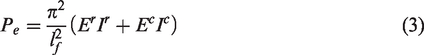
The test specimens were designed as shown in Figure 3. Each specimen includes three functional sections along its axial direction: the core energy-consumption section, the transition section, and the connection sections. The core energy-consumption section is the most important part because it determines the performance of the specimen. The connection sections were used to fix the specimen onto the test machine. The parts between the core energy-consumption section and the connection sections are the transitions. The transitions were designed as gradually varying cross-sections with four perpendicular steel ribs around the middle steel tube to avoid the concentration of stresses on the extended unprotected core steel tube or the welding positions.
Layout of triple-tube GFRP-steel BRB specimen (Units: mm).
Each specimen was named according to the convention depicted in Figure 4.
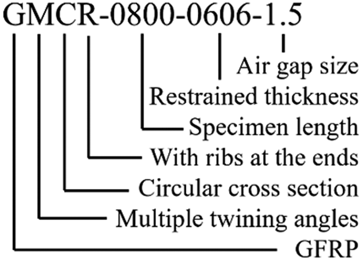
Naming convention for GFRP-steel BRB specimens.
The details of these specimens are listed in Table 1, where L, De, Di, and t are the length, external diameter, internal diameter, and thickness of the specimen, respectively; Δ is the air gap width; and θ is the twining angle of the fibers.
Dimensions of triple-tube GFRP-steel BRB specimens.
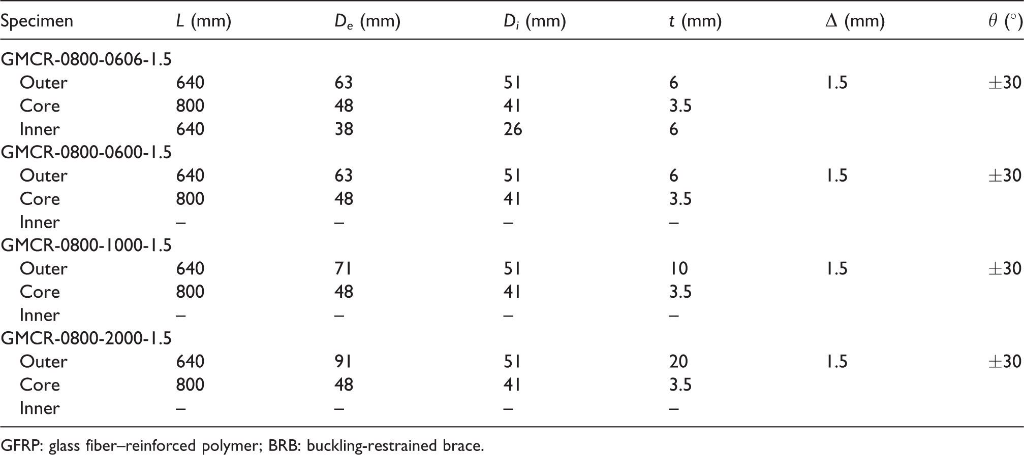
GFRP: glass fiber–reinforced polymer; BRB: buckling-restrained brace.
As shown in Table 1, these tests were used mainly to illustrate the effects of the applied loads on the Pe/Py ratio and the inner GFRP tubes. In addition, the improvements in energy consumption performance were compared and discussed based on the test results of four GFRP restrained specimens.
There were initial imperfections from the manufacturing of the specimens. Each core member was divided into eight cross-sections with lines along the axial direction, and each line was marked with 15 equidistant points. Before the tests, the imperfections of the steel core tubes were measured with a laser rangefinder sliding on a flat plate. All the imperfections were less than 0.5‰ of the specimen length, which indicated that the effect of initial imperfections would be minor for these tests.
Test setup
A series of pseudo-static tests were conducted on the triple-tube GFRP-steel BRB specimens with a 250 ton MTS Electro-hydraulic Servo Testing Machine (as shown in Figure 5) to obtain the failure modes, energy-consumption capability, and ultimate capacity of each specimen. During the testing, the applied forces were monitored automatically by the MTS system. The axial deformations of the steel core members were recorded by linear variable differential transformers (LVDTs) installed at the loaded end of each specimen. These recordings were used to check the effect of self-compression deformations of the MTS machine. The tests were controlled by the axial displacements. First, compression forces were applied to the specimen, then the axial cyclic loading was increased gradually in seven levels: L/600, L/300, L/200, L/150, L/100, L/75, and L/50. Each load level was applied twice, as shown in Figure 6.

Test setup.

Loading principle.
Test results
The specimens were tested according to the loading principle shown in Figure 6. During the tests, all the specimens exhibited good restraining capabilities. Only the GMCR-0800-0600-1.5 specimen was bent in the last loading cycle of compression force, and global failure did not occur in the other specimens. The final failure patterns are presented in Figure 7.

Failure of GFRP-steel BRB specimens in test: (a) final failure of GMCR-0800-0606-1.5, (b) end failure, (c) final failure of GMCR-0800-0600-1.5, (d) end failure, (e) final failure of GMCR-0800-1006-1.5, (f) end failure, (g) final failure of GMCR-0800-2006-1.5, and (h) end failure.
The test results listed in Table 2 indicate that all the specimens exhibited good performance before L/100, and there were no visible failure phenomena on the specimens. Next, the soft cushions failed at the first tension loading of L/75. This behavior indicates that the displacements in the axial direction exceeded the limits of the soft cushions, which caused the length of the transition part to increase. Then, local stability problems occurred in GMCR-0800-0606-1.5, GMCR-0800-1006-1.5, and GMCR-0800-2006-1.5. However, for GMCR-0800-0600-1.5, global instability failure occurred during the second compression loading of L/75. This failure occurred mainly because of the sudden decrease in flexural rigidity caused by the cracking of fibers that separated from the epoxy resin layer, as shown in Figure 8.
Failure of test specimens.

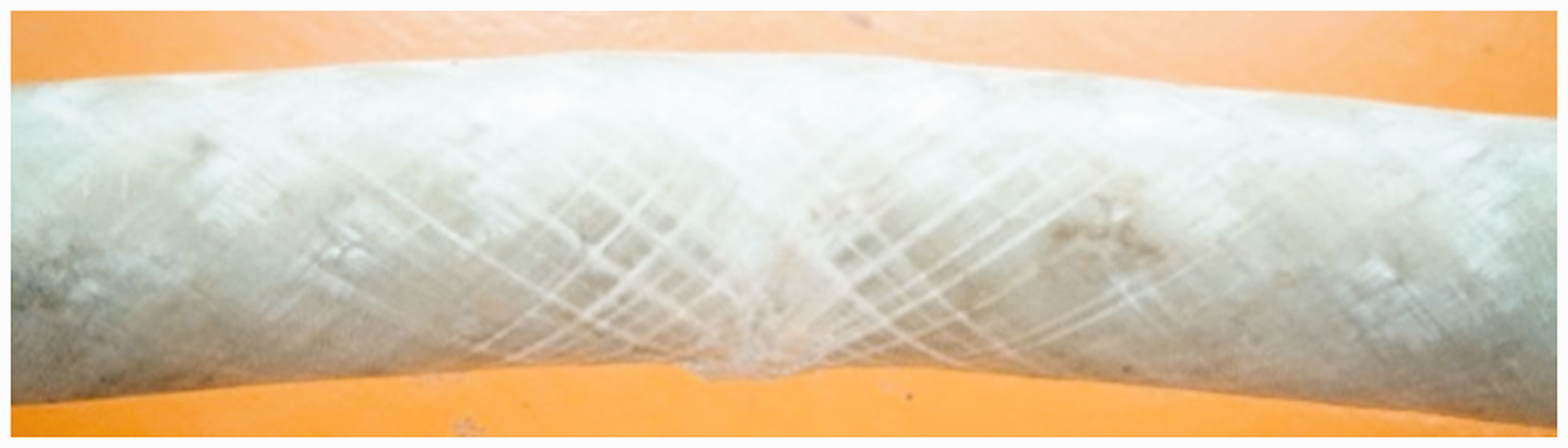
Cracked fibers of GMCR-0800-0600-1.5 specimen.
Discussion
Figure 9 shows the force versus displacement hysteretic and skeleton curves for the BRB specimens based on the measurements of loading force and total axial displacement recorded during the tests. Generally, the hysteretic curves are full and stable, which indicates that GFRP-steel BRBs have stable energy-consumption capabilities. Except for GMCR-0800-0600-1.5, the stiffness of the other specimens did not degrade during the entire tests. For GMCR-0800-0600-1.5, stiffness degradation occurred in the last cycle of compression loading, as shown in Figure 9(c). This degradation was due to global buckling. At that moment, the compression capacity of GMCR-0800-0600-1.5 also decreased dramatically by nearly 50%. To link the ultimate capacity points, the skeleton curves also indicate the decreasing of this specimen. The compression and tension capacities of the other specimens were relatively similar, which suggests that the energy-consumption performance under cyclic loading for this kind of triple-tube GFRP-steel BRBs is good.

Test results: (a) hysteretic curve of GMCR-0800-0606-1.5, (b) skeleton curve of GMCR-0800-0606-1.5, (c) hysteretic curve of GMCR-0800-0600-1.5, (d) skeleton curve of GMCR-0800-0600-1.5, (e) hysteretic curve of GMCR-0800-1000-1.5, (f) skeleton curve of GMCR-0800-1000-1.5, (g) hysteretic curve of GMCR-0800-2000-1.5, and (h) skeleton curve of GMCR-0800-2000-1.5.
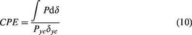
The charts in Figure 9 illustrate the energy-consumption capability of triple-tube GFRP-steel BRBs. Next, some indexes are used to compare the damping performance quantitatively. The following indexes are typically used to describe and examine the capabilities of BRBs: ultimate compression capacity (Puc), ultimate tension capacity (Put), equivalent yield strain (εy; the ratio of yielding displacement to length of yielding part), yield strength coefficient (γy), compression-tension asymmetry coefficient (β; the ratio of ultimate compression capacity to ultimate tension capacity), ductility (μ; the ratio of yielding displacement to ultimate compression displacement), the ratio of cumulative plastic deformation (CPD) and ratio of cumulative plastic energy (CPE). CPD and CPE are defined as follows
27

The values of each index are listed in Table 3, of which μ and CPD are the most important. According to the US Code ANSI/AISC 341-10, 28 the lower limits of these indexes are 10 and 200, respectively. As shown in Table 3, all the specimens conform to these limits.
Details of test results.
CPD: cumulative plastic deformation; CPE: cumulative plastic energy.
The test results indicate that GMCR-0800-0600-1.5 and GMCR-0800-0606-1.5 have nearly identical parameters, expect for the inner GFRP restrained tube. It should be noted also that their final failure modes are totally different, which means that the inner restrained tube contributes significantly to the buckling restraint of the steel core member in triple-tube GFRP-steel BRBs when the outer dimensions of components were limited by the environment. Besides, the differences among GMCR-0800-0600-1.5, GMCR-0800-1000-1.5, and GMCR-0800-2000-1.5 are only the outer restrained tubes. From the test results, it seems that there is no obvious enhance with the increasing of the outer restrained layers. The main reason is, when the restrain stiffness is large enough, that using the way to increase the outer layer thickness is not that effective. It means that in the designing period of this triple-tube GFRP-steel BRB, the ratio of Pe/Py should not be too large but must satisfy with the lower limitation value.
FE analysis
Numerical simulation is an important way to investigate the performance of triple-tube GFRP-steel BRB devices. Elaborate FE models were setup using the ABAQUS software package. The methods and details of the FE model were introduced.
FE model
Because GFRP is a kind of anisotropic material, a special model for the composite layer materials (Lamina) was used to simulate the proposed GFRP material. The properties of high-strength GFRP used in the tests are listed in Table 4. In addition, the Hashin Criterion was used in the model to simulate the progressive failure of the multiple-layer GFRP material. The kinematic model was used for steel tubes, and the value of the tangent modulus was defined as 2% of the elastic modulus.
Material properties of GFRP.

GFRP: glass fiber–reinforced polymer.
The ABAQUS/Explicit product was used for the model. Surface-to-surface interaction was applied on the main parts to simulate the contact actions. The penalty contact was adopted with a friction coefficient of 0.3, and the initial imperfection was defined as 1‰ of the length of steel tubes. S4R shell element was used to simulate the tubes, with 30 units in the radial direction. The approximate size of each S4R shell element was set at 5 mm. The generic FE model of the triple-tube GFRP-steel BRB specimens is shown in Figure 10.
FE model of triple-tube GFRP-steel BRB.
Verification
The pseudo-static tests with the cyclic loading conducted in section “Test programs” were simulated in ABAQUS. The simulation results matched closely with the test results. Taking GMCR-0800-0600-1.5 and GMCR-0800-0606-1.5 as examples, Figure 11 shows that the simulated deformation patterns of the specimens are identical to the test results. For GMCR-0800-0606-1.5, Figure 11(b) shows that the multi-wave buckling of the core member was also detected in the contours of the numerical simulation results at a scale factor of five, while the restrained members were straight. This observation indicates that the restraint mechanisms performed well during the test. Figure 11 also compares the hysteretic curves. As shown, the main features of the simulated curves match closely with the test results. For an example, the ultimate compression capacity of GMCR-0800-0606-1.5 monitored from test is 188.72 kN, while the result in simulation is 190.908 kN. The relative error is approximately 1.2%. In addition, the relative errors in other key parameters, such as the yield loads and yielding displacements are both less than 5%. This observation indicates that the FE model adequately simulated the mechanical behaviors and failure modes of the specimens.

Comparison between simulation and test results: (a) simulation of GMCR-0800-0600-1.5 (scale factor: 1), (b) simulation of GMCR-0800-0606-1.5 (scale factor for core member: 5), (c) comparison of GMCR-0800-0600-1.5, and (d) comparison of GMCR-0800-0606-1.5.
The relative errors between simulation and test results are listed in Table 5. It could be known that the maximum relative error of both GMCR-0800-0606-1.5 and GMCR-0800-0600-1.5 is less than 4%. It means that the simulation methods are reliable for this kind of BRB.
Comparison between simulation and test results.
Parametric study
The ratio of Pe/Py is among the key performance parameters of BRBs. As noted in section “Triple-tube GFRP-steel BRB,” the ideal value of Pe/Py for triple-tube GFRP-steel BRBs should be greater than 1.5; however, the actual lower limit of Pe/Py depends on more specific reasons.
Using the aforementioned FE model, the recommended lower limit of Pe/Py for GFRP-steel BRBs was investigated by comparing the performance of numerical samples within the range of 1.05–3.21, in which the value of Pe/Py ratio was varied by changing the thickness of the outer restrained components. It should be noticed that the following numerical samples were all designed as full-scale GFRP-steel BRB devices. The core steel tubes were 4.3 m long, with a cross-section of Φ121 × 4.0 mm. The outer and inner GFRP restrained tubes were each 4000 m long. The air gaps between these tubes and the core steel tube were 1.5 mm wide. The results of simulation samples, with various Pe/Py ratios 1.05, 1.10, 1.17, 1.22, 1.25, 1.30, 1.40, 1.49, 1.89, 2.31, 2.75, and 3.21, were plotted in Figure 12.

Effect of Pe/Py on energy-consumption performance.
Figure 12 shows that all the skeleton curves from the numerical samples are nearly identical on the tension side, but on the compression side, degeneration occurs for Pe/Py ratios less than 1.25. Especially, for Pe/Py values of 1.05 and 1.1, degeneration occurs at L/100. For samples with large enough Pe/Py ratios, the skeleton curves do not indicate degeneration. This performance conforms to the requirements specified in the corresponding codes.
The charts in Figure 13 compare some key indexes of BRBs. As shown in Figure 13(b) and (c), the values of μ and CPD are stable at Pe/Py ratios of 1.25 or higher, while the ultimate compression capacity and CPE fluctuate slightly. This observation indicates that the performance of BRBs is altered significantly when the Pe/Py ratio is not high enough to support the restraining function. However, when the Pe/Py ratio exceeds the lower limit value, the performance is stable. Therefore, the lower limit of the Pe/Py ratio for GFRP-steel BRBs should be greater than 1.25. Considering uncertainty factors, the suggested lower limit for design is 1.5, which is identical to the theoretical solution presented in section “Triple-tube GFRP-steel BRB.”

Effect of Pe/Py: (a) effect on ultimate compression capacity, (b) effect on ductility, (c) effect on CPD, and (d) effect on CPE.
Conclusion
Based on the aforementioned tests and analyses, the summary and conclusions of this study are as follows:
A new triple-tube GFRP-steel BRB was proposed, which integrates the advantages of composite materials. Both pseudo-static tests and numerical investigations were performed. The energy-consumption capabilities and failures were examined experimentally using four scaled specimens. Global buckling occurred only in one specimen (GMCR-0800-0600-1.5); this specimen had the lowest Pe/Py ratio among the specimens tested. The other three specimens exhibited good performance with effective restraint from the GFRP tubes. The functions of the inner GFRP restrained tubes were observed by comparing the results from the specimens. Although the inner tubes are thin and supply less flexural rigidity than the outer ones, they contributed successfully in avoiding global buckling failure in some special situations. The triple-tube GFRP-steel BRB specimens exhibited stable performance in terms of energy consumption and ductility. If properly designed, GFRP-steel BRBs can meet the required standards for ductility and CPD. An FE model was built and verified against the test data. The model results matched closely with the test results. Using this model, more detailed information about triple-tube GFRP-steel BRBs were obtained. The effects of the Pe/Py ratio on the performance of triple-tube GFRP-steel BRBs were investigated numerically. The lower limit of Pe/Py ratio 1.5 was defined based on theoretical derivation and numerical parametrical analysis. This value can be used as a design parameter for triple-tube GFRP-steel BRBs.
Footnotes
Handling Editor: James Baldwin
Declaration of conflicting interests
The author(s) declared no potential conflicts of interest with respect to the research, authorship, and/or publication of this article.
Funding
The author(s) disclosed receipt of the following financial support for the research, authorship, and/or publication of this article: The research presented in this paper was jointly supported by the Scientific Research Fund of Institute of Engineering Mechanics, China Earthquake Administration (grant no. 2019A02) and the National Natural Science Foundation of China (grant no. 51708521), and the National Key R&D Program of China (grant no. 2018YFC1504602).