
Abstract
The matching of constraint between laboratory specimens and actual cracked structures is a key problem of the accurate structure integrity assessment. Different laboratory specimens and the steam turbine blade with different constraints were selected, the matching of constraint between steam turbine blade and laboratory specimens was investigated. The results shown that the steam turbine blade with 2c = 50 mm, a/2c = 0.20 has a matching constraint with single edge-notched bend specimen with a/W = 0.6 and single edge-notched tensile specimen with a/W = 0.3. The steam turbine blade with 2c = 50 mm, a/2c = 0.25 has a matching constraint with single edge-notched bend specimen with a/W = 0.7. The steam turbine blade with 2c = 50 mm, a/2c = 0.30 has a matching constraint with single edge-notched bend specimen with a/W = 0.5 and single edge-notched tensile specimen with a/W = 0.1. The steam turbine blade with 2c = 50 mm, a/2c = 0.35 has a matching constraint with single edge-notched bend specimen with a/W = 0.4, compact tension specimen with a/W = 0.3 and central-cracked tension specimen with a/W = 0.7. The steam turbine blade with a = 15 mm, a/2c = 0.30 has a matching constraint with compact tension specimen with a/W = 0.7 and single edge-notched tensile specimen with a/W = 0.5. The steam turbine blade with a = 15 mm, a/2c = 0.40 has a matching constraint with compact tension specimen with a/W = 0.4. The steam turbine blade with a = 15 mm, a/2c = 0.50 has a matching constraint with single edge-notched bend specimen with a/W = 0.5.
Introduction
Constraint is the resistance of a structure against plastic deformation. 1 It was divided into out-of-plane constraint and in-plane constraint. The out-of-plane constraint is affected by the specimen dimension parallel to the crack front, and the in-plane constraint is affected by the specimen dimension in the direction of crack propagation. The loss of constraint, such as the decreasing of crack depth, will result in the increasing of the fracture resistance. 2 That is to say, different specimens and structures with different crack sizes have different constraints and fracture behaviours.
In current structure integrity assessment standards, the standard specimens have severely size requirements to ensure the highest constraint and the lowest fracture resistance.3–8 Moreover, the obtained fracture resistance data of the standard specimen by fracture mechanics test were selected to evaluate the safety of the structure. However, for the structures with lower constraints than standard specimen, the transfer of fracture resistance data from standard specimen to the actual cracked structures will produce a conservative result. Conversely, for some special structures with higher constraints than standard specimen, the transfer will result in a non-conservative result. Thus, for accurate structure integrity assessment, the constraint matching specimen (may not be the standard specimen) should be selected to assess the safety of the actual cracked structure, and the matching of constraint between laboratory specimens and actual cracked structures becomes the key problem of the structure integrity assessment.
To address this problem, several constraint parameters were established to quantify the constraint state, which contains the out-of-plane constraint parameter TZ9–11 and the in-plane constraint parameters T, 12 Q13,14 and A2. 15 These parameters have been used successfully to quantify the out-of-plane or in-plane constraint separately. Unfortunately, both out-of-plane and in-plane constraints generally existing in the actual structures, these parameters above cannot be used to establish the matching of constraint between laboratory specimens and actual structures.
Some unified parameters, such as φ16,17 and Ap,18,19 which can quantify both out-of-plane and in-plane constraints were further established. Compared with the constraint parameter φ, the unified parameter Ap can be used in the steel with higher toughness. 20 And with development of these unified constraint parameters, the matching of constraint can be researched in a brand-new angle of view.
In the previous studies, based on the unified constraint parameter Ap, the authors studied the matching of constraint between standard specimen and non-standard specimens, 21 between different laboratory specimens, 22 between cracked pipe structures and different laboratory specimens. 23 But for the steam turbine blade which is the core component of the steam turbine, 24 the constraint state is not clear yet, and the matching of constraint between the steam turbine blades and laboratory specimens has not been established. Thus, in this article, the constraints of cracked steam turbine blades were calculated, and the matching of constraint between the steam turbine blades and laboratory specimens was investigated.
Finite element calculation
Materials
To ensure the consistency with previous studies, the steel A508 was also selected. Its elastic modulus, Poisson’s ratio and yield strength at room temperature are 202,410 MPa, 0.3 and 514 MPa, respectively. The true stress–strain curve of the A508 steel was shown in Figure 1. 25

The true stress–strain curve of A508 steel. 25
The geometries of the steam turbine blades
The governing-stage moving blade which used in the steam turbine was selected in this study, it is also the core component of the steam turbine. To obtain the constraints of the cracked steam turbine blades, an imaginary initial crack with different crack lengths and crack depths was set near the pressure side and the junction with the blade root, as shown in Figure 2. When the crack depth a was changed, fixing the crack length 2c = 50 mm, and changing the a/2c = 0.15, 0.20, 0.25, 0.30, 0.35 and 0.45; when the crack length 2c was changed, fixing the crack depth a = 15 mm, and changing the a/2c = 0.30, 0.40 and 0.50.

The geometry of the steam turbine blade with initial crack.
The geometries of different laboratory specimens
To obtain the constraints of different laboratory specimens, the compact tension (CT), single edge-notched bend (SENB), single edge-notched tensile (SENT) and central-cracked tension (CCT) specimens were selected, and seven values of crack depths denoted as a/W = 0.1, 0.2, 0.3, 0.4, 0.5, 0.6 and 0.7 were set for each specimen. The geometries and sizes of different laboratory specimens were shown in Figure 3 and Table 1.
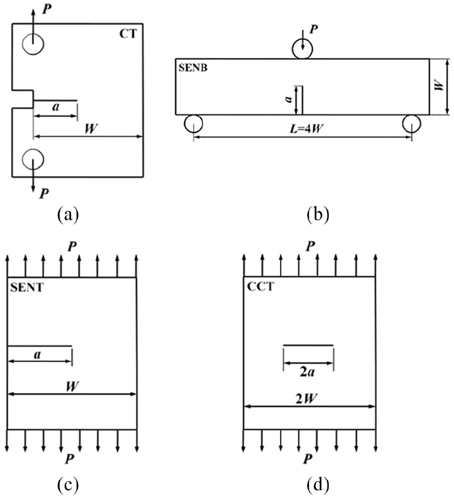
The geometries of different laboratory specimens: (a) SENB, (b) CT, (c) SENT and (d) CCT.
The sizes of different laboratory specimens.

SENB: single edge-notched bend; CT: compact tension; SENT: single edge-notched tensile; CCT: central-cracked tension.
Finite element model
The commercial finite element code ABAQUS was used in this study. In addition, the two-dimensional (2D) plane strain 8-node solid element with reduced integration (CPE8R) was used for different laboratory specimens, and the three-dimensional (3D) 8-node brick element with reduced integration (C3D8R) was used for the steam turbine blades. A fine mesh configuration which has a focused ring of elements surrounding the crack front was used in all the specimens and blades.18,19 The finite element model of typical steam turbine blade was shown in Figure 4, it contains 49,039 nodes and 44,865 elements.
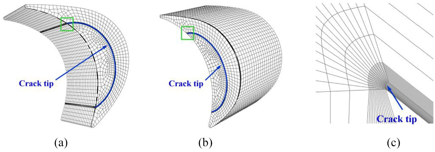
The mesh partition of the typical steam turbine blade model: (a) the front, (b) the back and (c) the local meshes of the square location in the (a) and (b).
Furthermore, for the SENB specimens, the load was applied at the up centre of the specimen by prescribing a displacement of 6 mm; for the CT specimens, the load was applied at the centre of the loading hole by applying a concentrated load; for the SENT and CCT specimens, the load was applied by applying a uniform load. For the blade, the internal pressure was 15.2184 MPa and the bending moment was applied on the back of the steam turbine blade for loading.
And then, the parameter Ap which defined as

was calculated, where APEEQ is the area surrounded by the equivalent plastic strain isoline at crack tip and Aref is the reference area surrounded by the equivalent plastic strain isoline in a standard test at fracture.18,19 In addition, the
Because the slope of the
Results and discussion
The matching of constraint between steam turbine blades and SENB specimens
The comparisons of

The matching of constraints between steam turbine blades and SENB specimens: (a) the blade with 2c = 50, a/2c = 0.15 and SENB; (b) the blade with 2c = 50, a/2c = 0.20 and SENB; (c) the blade with 2c = 50, a/2c = 0.25 and SENB; (d) the blade with 2c = 50, a/2c = 0.30 and SENB; (e) the blade with 2c = 50, a/2c = 0.35 and SENB; (f) the blade with 2c = 50, a/2c = 0.45 and SENB; (g) the blade with a = 15, a/2c = 0.30 and SENB; (h) the blade with a = 15, a/2c = 0.40 and SENB; and (i) the blade with a = 15, a/2c = 0.50 and SENB.
It can be found that for the SENB specimens, with increasing of the a/W, the slopes of the
In addition, the
The values of a and b for the mathematical expressions of the SENB specimens and steam turbine blades.

SENB: single edge-notched bend.
Combined with mathematical expressions, and compared with the
The matching of constraint between steam turbine blades and CT specimens
The comparisons of

The matching of constraints between steam turbine blades and CT specimens: (a) the blade with 2c = 50, a/2c = 0.15 and CT; (b) the blade with 2c = 50, a/2c = 0.20 and CT; (c) the blade with 2c = 50, a/2c = 0.25 and CT; (d) the blade with 2c = 50, a/2c = 0.30 and CT; (e) the blade with 2c = 50, a/2c = 0.35 and CT; (f) the blade with 2c = 50, a/2c = 0.45 and CT; (g) the blade with a = 15, a/2c = 0.30 and CT; (h) the blade with a = 15, a/2c = 0.40 and CT; and (i) the blade with a = 15, a/2c = 0.50 and CT.
The values of a and b for the mathematical expressions of the CT specimens and steam turbine blades.

CT: compact tension.
Compared with the
Because the CT specimen is another standard specimen, the matching conditions between steam turbine blades and CT specimens also shows that it is not appropriate if only the standard specimen was selected in the structure integrity assessment. Compared with the SENB specimens, the constraints of CT specimens reflect the same change rule, but have a much wider range.
The matching of constraint between steam turbine blades and SENT specimens
The comparisons of

The matching of constraints between steam turbine blades and SENT specimens: (a) the blade with 2c = 50, a/2c = 0.15 and SENT; (b) the blade with 2c = 50, a/2c = 0.20 and SENT; (c) the blade with 2c = 50, a/2c = 0.25 and SENT; (d) the blade with 2c = 50, a/2c = 0.30 and SENT; (e) the blade with 2c = 50, a/2c = 0.35 and SENT; (f) the blade with 2c = 50, a/2c = 0.45 and SENT; (g) the blade with a = 15, a/2c = 0.30 and SENT; (h) the blade with a = 15, a/2c = 0.40 and SENT; and (i) the blade with a = 15, a/2c = 0.50 and SENT.
The values of a and b for the mathematical expressions of the SENT specimens and steam turbine blades.
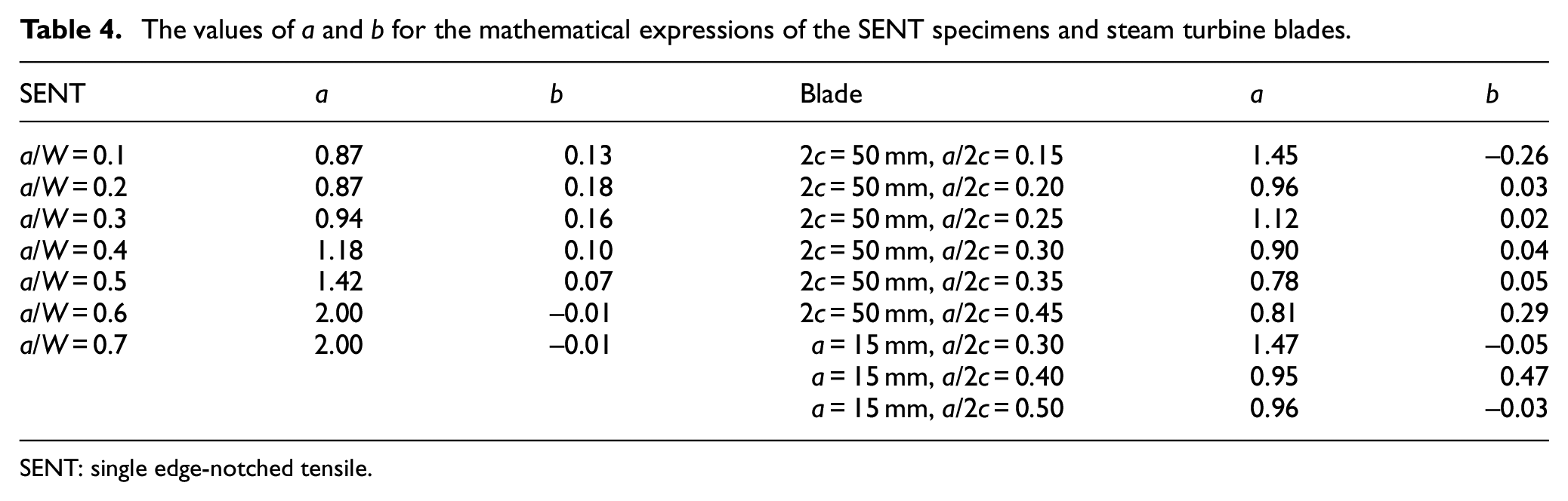
SENT: single edge-notched tensile.
Compared with the
The constraints of the SENT specimens in this study is high, it is related to the loading mode. The constraints of the SENT specimens under different loading modes have been discussed in the previous study. 22
The matching of constraint between steam turbine blades and CCT specimens
The comparisons of

The matching of constraints between steam turbine blades and CCT specimens: (a) the blade with 2c = 50, a/2c = 0.15 and CCT; (b) the blade with 2c = 50, a/2c = 0.20 and CCT; (c) the blade with 2c = 50, a/2c = 0.25 and CCT; (d) the blade with 2c = 50, a/2c = 0.30 and CCT; (e) the blade with 2c = 50, a/2c = 0.35 and CCT; (f) the blade with 2c = 50, a/2c = 0.45 and CCT; (g) the blade with a = 15, a/2c = 0.30 and CCT; (h) the blade with a = 15, a/2c = 0.40 and CCT; and (i) the blade with a = 15, a/2c = 0.50 and CCT.
The values of a and b for the mathematical expressions of the CCT specimens and steam turbine blades.

CCT: central-cracked tension.
Compared with the
The results above show that the constraint matching laboratory specimen with the steam turbine blade can be found in this way, but the matching specimen not always the standard specimen. For the fracture behaviours of the constraint matching specimen and structure can be transferred each other, the constraint matching specimen should be found and selected first in the structure integrity assessment. And then, the tested mechanics properties of the constraint matching specimen can be used in the assessment to improve the accurately of the assessment.
Generally, the defect sizes can be measured by non-destructive testing. And then, based on the relevant standards, the defects in the structure were usually merged and characterized by a semi-elliptical or elliptical crack. The parameters ‘a’ and ‘c’ of the blade can be determined in this way. This is also the reason for the selection of the semi-elliptical crack in this study. Actually, in the assessment of the steam turbine blade, the parameters ‘a’ and ‘c’ of the blade are not always needed to be determined. When the crack size was measured by non-destructive testing, the finite element model of the blade with the actual crack can be built to calculate the computed line. And then, based on the methods in this article, different specimens can be calculated to try to find an accurate constraint matching specimen with the cracked blade.
The summary of the constraint matching between steam turbine blades and laboratory specimens
In order to descript the results in a concise and clear way, the steam turbine blades with 2c = 50 mm, a/2c = 0.15; 2c = 50 mm, a/2c = 0.20; 2c = 50 mm, a/2c = 0.25; 2c = 50 mm, a/2c = 0.30; 2c = 50 mm, a/2c = 0.35; 2c = 50 mm, a/2c = 0.45; a = 15 mm, a/2c = 0.30; a = 15 mm, a/2c = 0.40; and a = 15 mm, a/2c = 0.50 were marked as blade 1, blade 2, blade 3, blade 4, blade 5, blade 6, blade 7, blade 8 and blade 9, respectively.
The summary of the constraint matching between steam turbine blades and different laboratory specimens were shown in Table 6. If the constraints of the specimen and the blade were matching, marking as yes in Table 6. If the constraints of the specimen and the blade were un-matching, nothing is marked in Table 6.
The summary of the constraint matching between steam turbine blades and laboratory specimens.

SENB: single edge-notched bend; CT: compact tension; SENT: single edge-notched tensile; CCT: central-cracked tension.
Conclusion
The matching of constraint between steam turbine blade and different laboratory specimens has been established.
The constraints of the steam turbine blades with different crack sizes were quite different, if only the standard specimen or only one specimen was selected to assess the structure integrity of the blades, the inaccurate assessment results will be obtained.
In the structure integrity assessment, a specimen with similar constraint to the blade can be selected for the mechanics test, and the tested mechanics properties can be used in the assessment to improve the accurately of the assessment.
The CCT specimens need to be avoided for selecting in the assessment of the steam turbine blades.
Supplemental Material
1 – Supplemental material for A study on the matching of constraint between steam turbine blade and laboratory specimens
Supplemental material, 1 for A study on the matching of constraint between steam turbine blade and laboratory specimens by Jie Yang, Yuman Liu and Haofeng Chen in Advances in Mechanical Engineering
Footnotes
Handling Editor: Jose Ramon Serrano
Declaration of conflicting interests
The author(s) declared no potential conflicts of interest with respect to the research, authorship and/or publication of this article.
Funding
The author(s) disclosed receipt of the following financial support for the research, authorship and/or publication of this article: This research was funded by National Natural Science Foundation of China, grant numbers 51975378 and 51605292.
Supplemental Material
Supplemental material for this article is available online.
References
Supplementary Material
Please find the following supplemental material available below.
For Open Access articles published under a Creative Commons License, all supplemental material carries the same license as the article it is associated with.
For non-Open Access articles published, all supplemental material carries a non-exclusive license, and permission requests for re-use of supplemental material or any part of supplemental material shall be sent directly to the copyright owner as specified in the copyright notice associated with the article.