
Abstract
In this article, flexural vibration and its power flow of an axially loaded beam with arbitrary boundary and non-uniform elastic foundation are analyzed via energy principle in conjunction with Rayleigh–Ritz procedure. A general solution is assumed as a modified version of Fourier series supplemented with boundary-smoothing auxiliary terms. Effects of axial load and elastic foundation of the beam are taken into account in terms of potential energy in system Lagrangian. Critical load of this axially loaded beam is obtained under elastic boundary condition and non-uniform foundation. Numerical examples are then presented to demonstrate the reliability and effectiveness of the established model by comparing results with those available in literature or calculated using finite element method. Results show that the current model can make an accurate dynamic analysis for the elastically restrained beam with axial load and non-uniform elastic foundation. Influence of some important factors, including boundary restraint, axial load, and non-uniform foundation, on the vibration characteristics and power flow transmission are studied and addressed. It is found that the supporting condition has a significant influence on power flow distribution across the whole beam, in which the shear force component plays a dominant role for the power flow transmission.
Introduction
As one of the basic structural elements, beam structure has been widely used in almost every field of engineering occasions. For the propulsion system of ships, motor vehicle, and aircraft, vibration analysis of the propulsion shafting is usually performed through the simplification into beam model with elastic foundation and axial load. Obviously, a good understanding on its dynamic characteristics will be of fundamental significance for the efficient design and operation of such complex system. For this reason, a lot of research effort has been devoted to the flexural vibration analysis of beam structures resting on elastic foundation and/or subjected to axial load.1–3
Bokaian 4 calculated the frequency parameters of a uniform beam under constant axial compressive force, and the buckling condition under classical boundaries was also discussed. Al-Raheimy 5 proposed an analytical solution for natural frequency and critical pressure of simply supported beams under axial force, and the effect of various cross-section types of beam on the corresponding critical pressure were analyzed. Chen et al. 6 employed the energy finite element method (FEM) to analyze the high frequency vibration of beam structure subjected to axial load, and discussed the influence of axial force on energy transmission and capacity loss. Naguleswaran 7 examined the transverse vibration of uniform Euler–Bernoulli beams under linearly varying tensile, partly tensile, or fully compressive axial force distributions, and formulated the frequency equations of the 16 combinations of classical boundary conditions. Xing and Wang 8 established a general model for the free vibration analysis of a Euler–Bernoulli beam restrained with two rotational and translational elastic springs under a constant axial load.
Besides the simple beam model, beam problem with various complex factors also attracts research attention from many researchers. Caddemi and Caliò 9 investigated the influence of axial force on the vibration characteristics of Euler–Bernoulli beams with various concentrated cracks and boundary conditions. Yang et al. 10 conducted an analytical study on the free and forced vibration analyses of functionally graded material (FGM) Euler–Bernoulli beam containing open edge cracks, which is subjected to an axial compressive force and concentrated transverse load moving along the longitudinal direction. Their results show that both the free vibration and dynamic response are more significantly affected by the presence of axial compression than the edge crack. Borbon and Ambrosini 11 examined the influence of axial load on the natural frequencies of thin-walled beams under classical boundary conditions. Numerical and experimental studies about natural frequencies of thin-walled beams axially loaded are conducted by Li et al. 12 Free vibration of composite beams under axial load was studied by Vo et al. 13 and Wang et al. 14 Wu and Chang 15 derived the exact natural frequencies and its associated mode shapes for an axial-loaded multi-stepped Timoshenko beam carrying any number of various concentrated elements using the presented continuous-mass transfer matrix method (CTMM). Moreover, Euler formula is usually used to check the stability of beam under axial force, in which the critical load can be obtained. This study shows that a zero natural frequency could initiate the instability (Euler buckling) of the beam and a necessary condition is that at least one of the axial forces must be compressive. Some investigation also indicates that beam structure will lose its stability even if the axial force is less than the critical load.
For a practical shafting system, it usually consists of the transmission shaft, bearing and other accessories, and so on. For this reason, vibration analysis of beams with point support or elastic foundations is also extensively considered. Wang et al. 16 analyzed a cantilever beam with intermediate supports and discussed the influence of intermediate supporting stiffness on beam frequencies. Boreyri et al. 17 studied the vibration behavior of variable cross-section beams with various boundary conditions resting on elastic foundation. For a similar model, Mirzabeigy 18 further introduced the axial force and developed a semi-analytical method using Taylor expansion to analyze the vibration characteristics of beams under several classical boundary conditions. Kim 19 investigated the vibration behavior and stability of an infinite Bernoulli–Euler beam resting on elastic foundation under axial uniform loads. Influence of axial load on vibration characteristics was analyzed and the expressions of critical frequency and critical load were also obtained. For the Timoshenko beam subjected to axial load, influence of Winkler foundation with different parameters and torsional spring stiffness on beam vibration was examined via Green’s function. 20 Özturk and Coşkun 21 provide the analytical results for the free vibration analysis of beam on elastic foundation for three different axially loaded cases under classical boundary conditions. Hızal and Çatal22,23 present a comprehensive analysis on the effect of rotary inertia and higher modes on the dynamic response of axial-load beams resting on modified Vlasov foundation and two-parameter elastic foundation. For more accurate simulation of the bearing support, vibration study of partially supported beams was also carried out by Eisenberger et al. 24 By transforming the partial support into an external load, Motaghian et al. 25 discussed the vibration characteristics of beam structure with various boundaries. Moreover, Farzad and Mohammad26,27 and Ashraf et al.28 studied the vibration of nanobeams with classical boundary conditions and various kinds of foundations.
In most of the above existing studies, boundary condition of structural systems tends to be idealized such as simply supported, clamped, and free. For the analysis of real systems, the nearest ideal boundary condition is usually chosen for approximate modeling. However, small deviation from such ideal case is frequently encountered in various engineering practices, which are also called as the non-ideal boundary conditions. 29 Yayli et al. 30 explored an analytical solution for the free vibration of elastically restrained Euler–Bernoulli beam resting on elastic foundation, and the effect of various spring stiffness of boundary conditions and elastic supports on its vibration behavior was discussed. Lee 31 modeled a non-ideal boundary condition as a linear combination of the idealized simply supported and clamped boundary conditions with the weighting factors k and 1–k, respectively. Ghadiri et al. 32 studied the vibration characteristics of Bernoulli beams subjected to axial loads and attached with the additional mass, and it was found that the critical pressure of beam structure will decrease under the imperfect boundary conditions. Literature survey shows that these studies are mainly limited to the case of single beam under axial force resting on uniform foundation with classical boundary conditions. However, from the viewpoint of engineering practice, the shafting system will suffer from the non-ideal boundary conditions, for example, the bearing clearance and variable stiffness,33,34 which have not been adequately studied.
Motivated by such limitation in literature, the aim of this article is to establish a more general model for the vibration analysis of beams with non-uniform elastic foundation subjected to axial load. In order to make the beam displacement expression sufficiently smooth in the entire solving region [0, L], Fourier series with boundary-smoothing auxiliary terms are employed for admissible function construction. All the unknown coefficients are determined in conjunction with energy principle description of beam structure through Rayleigh–Ritz procedure. Numerical examples are presented to validate the proposed model by comparing with those from other approaches in literature. Based on the model established, influence of some important factors, including boundary restraints, non-uniform elastic foundations, on the vibration characteristics of beam structure are studied and addressed. Moreover, power flow analysis is also conducted to illustrate the vibrational energy transmission behavior in such beam structure. Finally, some concluding remarks are made.
Theoretical formulations
Model description
As shown in Figure 1, the transverse vibration of an axially loaded beam with elastic boundary condition and non-uniform foundation will be considered in this work. For the harmonic oscillation, transverse vibration of beam structure will be assumed as W(x, t) = w(x)ejωt, in which w(x) is non-dimensionless displacement modal shape function and ejωt represents the normal coordinate function which corresponds to the time-dependent part of the transverse deflection. E, I, F, and A are the modulus of elasticity, moment of inertia, the applied axial load, and cross-section area of beam structure, respectively. k(x) is the non-uniform coefficient variation of elastic foundation, in which f(x) can be of arbitrary function form. L is the length of beam, and x is the independent coordinate along beam longitudinal direction. KR and KT are the rotational and translational restraining spring stiffnesses at the both end, which can simulate all the classical boundary conditions as well as their combination by simply setting the stiffness coefficients accordingly. Figure 1(b) shows the internal force distribution and balance on a beam infinitesimal element, in which Fk is the force generated by internal support. M and Q are the bending moment and shearing force, respectively. Then, considering the equilibrium equation on the translational direction, one will get


(a) Flexural vibration of beam structure with elastic boundaries and non-uniform foundation subjected to axial load; (b) internal and external forces applied on a beam infinitesimal element.
Making use of the bending moment equilibrium with respect to the point O will lead to

For the assumption of small deformation, the following approximation can be made
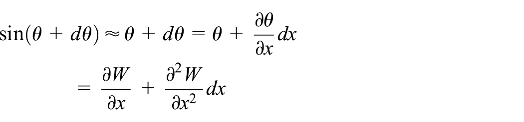
Substituting equations (2) and (3) into equation (1), one can have

In conjunction with the relationship between bending moment M and shear force Q, the governing differential equation under the compressive axial load can written as 35

where F is the compressive axial load. There is an additional moment term due to the existence of such constant axial load F.
Based on the force equilibrium and geometric coordination at the elastic restraints, the equations for such general boundary condition will be

and
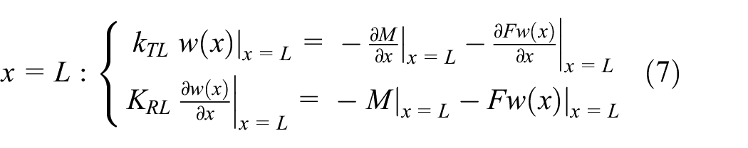
in which kT0 and KR0 are, respectively, the stiffness coefficients for the translational and rotational springs at the end x = 0, and similar meaning can be deduced for the right end of x = L. Various boundary conditions can be obtained by setting these two types of restraining stiffnesses accordingly. For example, the clamped end can be realized by taking these two spring coefficients as infinity, which can be represented by a very large number, such as 1012, in numerical calculation.
Energy equation and its solution procedure
In most of the existing studies, vibration analysis of beam structure under axial load and elastic foundation are mainly studied for the case of classical boundary conditions.24,25 In order to analyze the vibration characteristics of beam structure shown in Figure 1, a unified solution will be established based on energy principle description of beam system, which will bring the benefit to account for any other additional sub-systems in a more straightforward way. Lagrangian function for the transverse vibration of beam with general boundary condition and elastic foundation subjected axial load can be written as

where L is the system Lagrangian; V and T are the total potential and kinetic energies; Vbeam and Tbeam are the potential and kinetic energies associated with beam transverse vibration; and Vsp and VF are the potential energies stored in elastic foundation and the extra potential energy caused by axial load applied on the beam.
Potential energy Vbeam of beam with general elastic boundaries can be written as

In this work, arbitrary stiffness distribution of elastic foundation is considered, and the corresponding potential energy Vsp is

in which k0 is the stiffness coefficient amplitude, and f(x) is the foundation stiffness variation function defined in the region of [x1, x2].
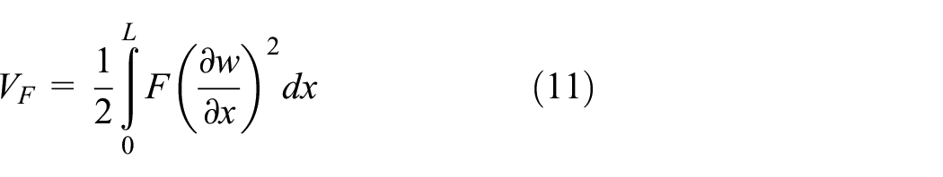
When the axial load is applied to the both ends of the beam, there will be an equal force on its any cross section. From equation (1), it can be seen that the introduction of extra axial force will affect the bending moment in the beam, and its relevant potential energy can be written as
The total kinetic energy of the vibrating beam structure is

where ω is the radian frequency, and ρ and S are, respectively, the beam mass density and its cross-section area.
Once the system Lagrangian is formulated, the remaining thing is to choose the appropriate admissible function. Differential continuity of the constructed function has significant influence on the final convergence and accuracy. Fourier series is usually employed for vibration analysis of beams in structural dynamics, which is mainly suitable for the case of classical boundary conditions, such as simply supported. When the elastic boundary restraints are considered, some issues of differential discontinuities associated with the traditional Fourier series will be encountered, which will further affect the solution convergence and performance. For this reason, boundary smoothed supplementary functions will be introduced to the standard Fourier series with the aim to remove all these discontinuities associated with the spatial differentiation of displacement field function. In this work, flexural displacement function of beam under axial load is expanded as

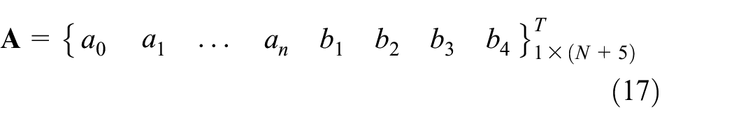
where w(x) is the beam displacement function; an is the Fourier series coefficients; ξ1(x), ξ2(x), ξ3(x), and ξ4(x) are the boundary smoothed auxiliary functions, with b1, b2, b3, and b4 as their corresponding weight coefficients. It should be noted that the choice of the supplementary functions is not unique, while the appropriate form will be helpful for simplifying the subsequent mathematical formulations. For more detail about such supplementary expressions, one can refer to our previous work. 36
Substituting the constructed admissible function equation (13) into system Lagrangian equations (8)–(12), minimizing it with respect to all the unknown coefficients and truncating the Fourier series into finite number n = N, one will obtain the system characteristic equation in matrix form. Through such process of minimization, one will find that the positive term (potential energy term) in the Lagrangian equation (8) contributes to the system stiffness matrix, and the negative term (kinetic energy term) devotes to the mass matrix. Corresponding stiffness and mass matrices deduced from equations (9)–(12) are

where


and
in which
The traditional dynamic analysis is frequency response relationship between the structural response, such as displacement, velocity and acceleration, and the external excitation. In comparison, power flow analysis can account for the structural response, namely, velocity and internal force simultaneously, which then can give a whole information about the vibrational energy transmission within the structure under certain frequency. For the vibration propagation in structure, in essence, it is the transmission of vibrational energy, and it is believed that the analysis of power flow can give a useful insight to the low-vibration design as well as its subsequent attenuation in various structures. Thanks to the sufficient smoothness of constructed admissible function in the whole solving region, the various order spatial derivations of beam displacement function can be calculated in a straightforward way, namely, in terms of term-by-term operation. Power flow can be seen as the time average of vibrational energy transfer across any section of beam structure. Power flow through per unit cross-sectional area of the beam shown in Figure 1 can be calculated as 37

in which * denotes the complex conjugate, and Re{ } is the real part of complex variable. Q and M are the transverse shear force and bending moment in beam structure, respectively.
These two variables can be calculated through the corresponding spatial derivatives of beam displacement function, namely

As mentioned above, supposition of the standard Fourier series and auxiliary functions in equation (13) can guarantee the sufficient continuity of various spatial derivatives in the entire solving domain, including the general elastic end supports. Power flow and structural intensity can be derived through a straightforward post-processing operation using the dynamic response information
Numerical results and discussion
In this section, several numerical examples will be presented to demonstrate the reliability and effectiveness of the proposed model for analyzing transverse vibration of beam with axial load and internal supports. In the current model, arbitrary distribution of the elastic support with variable stiffness and various axial force (including both the tensile and compressive forces) can be solved by just changing the corresponding coefficients. For the elastic boundary, when the restraining stiffness is taken as a medium number (0 to+∞), the elastic restraint is actually achieved. Any introduction or change of boundary condition, elastic support, and axial load will need not much modification on the theoretical formulation and simulation code. In the subsequent analysis, non-dimensional frequency parameter and restraining stiffness will be used, with their definitions as
Beam with axial load under classical boundary conditions
Euler formula also called critical load was first investigated by the mathematician Leonhard Euler who gave the maximum axial force that a beam can carry without buckling. The formula derived by Euler for the critical load of a long slender beam is given as follows

where Fcr is the maximum or critical force, and μ is beam effective length factor whose value depends on the beam boundary conditions.
The Euler’s critical load of a single beam under classical boundary conditions has been studied and the effective length factor is listed in Table 1. For the classical boundary conditions, analytical solution of the effective length factor can be obtained from the function of bending moment of beam structure.
Effective length factor μ of beam structure under classical boundary conditions.

First, a simply supported beam with axial load is considered, which can be easily modeled under the current framework. The tensile force (+F) and compressive force (–F) are both accounted for, and the analytic solution of natural frequency derived in Al-Raheimy 5 is used for comparison. Tabulated in Table 2 is the non-dimensional natural frequencies of such beam calculated from the current model. It can be seen that these two results can agree very well with each other. While increasing the tensile force, there is an increase trend for the natural frequency due to the increase of beam stiffness at the same mass which could be seen from equation (5). Similarly, increasing the amplitude of compressive load will decrease the beam effective stiffness resulting in a decrease of natural frequency, and the fundamental modal frequency will become zero when the compressive force is equal to the critical load (EIπ2/L2), which will correspond to the Euler buckling condition as mentioned above. Moreover, the effect of axial load on the modal frequency will become weaker for the higher order modes.
The first five non-dimensional natural frequencies of a simply supported beam with various axial loads.

Results of non-dimensional natural frequencies in parentheses are taken from Al-Raheimy. 5
Furthermore, Figure 2 presents the variation tendency of fundamental frequency with the change of axial force amplitude under different classical boundary conditions. It can be observed that the fundamental modal frequency has a sudden change when the axial load (both the compressive and tensile forces) is near to the critical load which should be avoided for structures in various engineering practice. By comparing these three curves, as we can see that boundary condition has a significant influence on the critical load of beam structure, the critical load of beam with C-F boundary is much less than those with other two end conditions. In other words, beam structure with C-F boundary condition will tend to be more unstable. In this figure, the dashed line represents the value of critical load for beams under certain boundary condition, which can coincide well with the results tabulated in Table 1. For the cases of C-F and C-C boundary conditions, the left ends of these curves are zero, which can coincide with the results made from their analytic solutions. However, for the beam with C-S boundary restraints, shown as the circle marker, the left end of the curve is not zero which means only the approximate value can be obtained as given in Table 1.

Variation of fundamental frequency of beam structure with various axial loads under different boundary conditions.
In order to illustrate the influence of axial load on beam mode shapes, Figure 3 shows the first two normalized mode shapes of axially loaded beam under C-F, C-S, and C-C boundary conditions, in which the non-dimensional parameters are utilized for the axial loads, and the mode shapes are normalized through the division by the maximum value in each subplot. From these plots, it can be found that the change of axial loads can affect the mode shape to some extent, especially for the fundamental mode. For the asymmetric boundary restraints, such as C-S, there is general trend for the mode shapes which will move slightly to the right end. For the symmetric boundary condition, for example, C-C, the amplitude of mode shape corresponding to the compressive load will be much larger than those of tensile load, especially for the peak region of the fundamental mode. However, there is little influence of axial load on the second mode shape under such boundary condition.

The first two normalized mode shapes of the axially loaded beams under C-F, C-S, and C-C boundary conditions: (a) the first mode shape of C-F beam, (b) the second mode shape of C-F beam, (c) the first mode shape of C-S beam, (d) the second mode shape of C-S beam, (e) the first mode shape of C-C beam, and (f) the second mode shape of C-C beam.
Beam with constant axial load and full elastic foundation
In this part, vibration characteristics of axially loaded beam will be studied, for which a complete elastic foundation is assumed across the whole beam. For comparison purpose, analytic solution of natural frequency for simply supported beam will be used, namely

in which m means the mode order and the stiffness k0 is a constant.
Tabulated in Table 3 is the fundamental frequencies of a simply supported beam resting on elastic foundation, in which α represents the multiples of stiffness k0 whose value is set to 102EI/L4. It can be observed that the fundamental frequencies predicted by the proposed method are in good agreement with those results in parentheses which are obtained from equation (21). Fundamental frequencies will increase when the values of k0 and F increase. Influence of axial load applied on beam would be more significant when the k0 value is close to zero, and the effect of axial force will become weak when the k0 value raises to 102EI/L4.
Fundamental frequencies of a simply supported beam with elastic foundation and axial loads.

Non-dimensional frequencies in parentheses are calculated from equation (21).
Figure 4 shows the effect of full elastic foundation stiffness on critical load of beam structure under different boundary conditions, in which the y-axis coordinate is the ratio of the current critical load to the critical load without elastic foundation under certain boundary condition. As we can see that for the classical boundary conditions, the linear relationship can be used to describe the tendency of raising stiffness α and the corresponding ratio. For the elastic boundary supports on the right end, elastic restraining springs
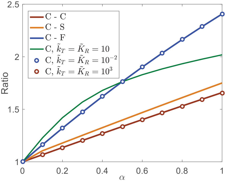
Effect of a complete elastic foundation stiffness on the critical load of beam structure under various boundary conditions.
Since the current model is based on energy principle, any non-uniform stiffness of internal supporting condition in arbitrary functions can be easily taken into account through the potential energy description in system Lagrangian. Here, as an example, f(x) = (ax + b) q will be dealt with to consider such complex supporting conditions. Presented in Table 4 are the first five modal frequencies of C-F beam resting on elastic foundation across the whole beam with the stiffness distribution as f(x) = (ax + b) q and k0 = 102EI/L4. Axial force F is zero in this case. The frequencies agree very well with the results calculated from COMSOL. It is illustrated that the coefficient change of a and q of the elastic support has great influence for the relatively lower modal frequencies. With the increase of a and q, the modal frequency will raise in which q has much greater influence, which will lead to a rapid increase of f(x). The effects of will become weaker for the higher mode order.
The first five modal frequencies of C-F beam with non-uniform elastic foundation, f(x) =(ax + 1) q .

Non-dimensional natural frequencies in parentheses are calculated from COMSOL.
The percentage differences in the frequencies between these two methods.
Axially loaded beam with partial elastic foundation
In vibration analysis of ship propulsion shafting, its bearings are usually simplified as the point supports are applied at the concentrated position. In fact, there is actually a contact surface for the bearing support, in which a certain length should be also taken into account. In the current solving framework, transverse vibration of beam structure resting on a partial elastic foundation can be readily analyzed by changing the integration range in equation (10) accordingly. The first five non-dimensional natural frequencies of flexible beam with simply supported and clamped boundary conditions are obtained in Table 5, in which the axial load F is set to zero and constant stiffness of partial elastic foundation
The first five non-dimensional natural frequencies of simply supported and clamped beam resting on partial uniform elastic foundations.
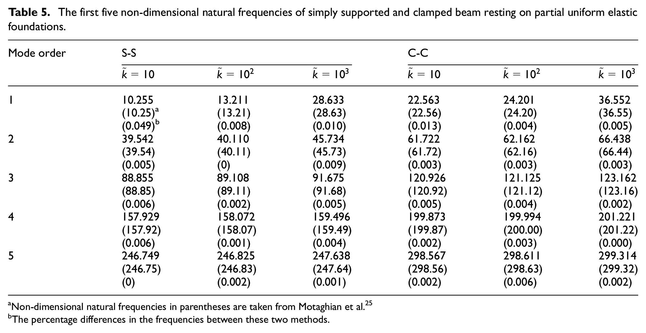
Non-dimensional natural frequencies in parentheses are taken from Motaghian et al. 25
The percentage differences in the frequencies between these two methods.
Table 6 presents the fundamental frequencies of axial loaded beam under C-F boundary condition, in which the partial elastic foundation x2 = L and the support stiffness is 102EI/L4. It can be seen that the frequency parameter will increase along with axial force, and the variation range is smaller because the axial force range is small in this case. Frequency parameter will decrease when the coefficient x1 becomes bigger which means the length of the partial support becomes short, namely, less structural restraint is applied to the axially loaded beam.
Variation of the fundamental frequencies of C-F beam resting on partial elastic foundation with different axial loads.
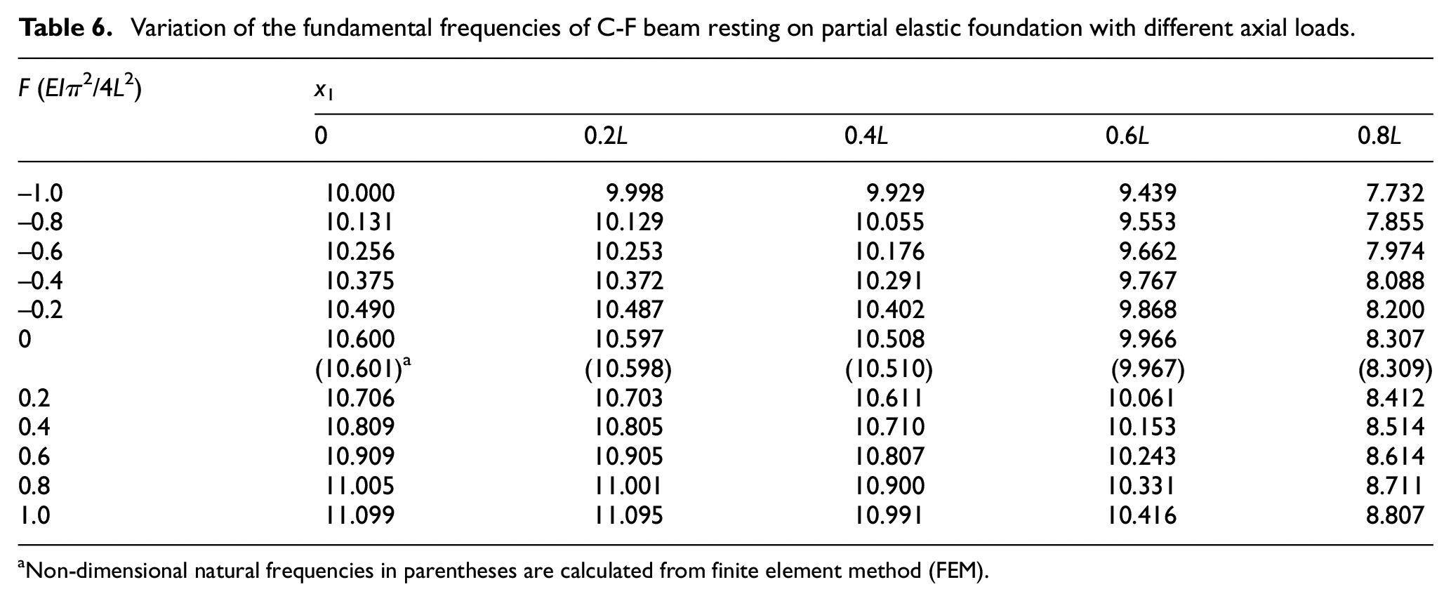
Non-dimensional natural frequencies in parentheses are calculated from finite element method (FEM).
Power flow analysis of C-F beam with partial elastic foundation
In this section, energy transmission characteristics of a cantilever beam with various partial elastic foundation will be investigated. In the current solving framework, all these internal forces used for the power flow analysis can be calculated readily through the term-by-term differential operation on the beam displacement function.
From the viewpoint of structural dynamics, power flow is one type of structural forced response. In fact, all the system dynamic information of beam structure is stored in the Fourier series coefficient vector
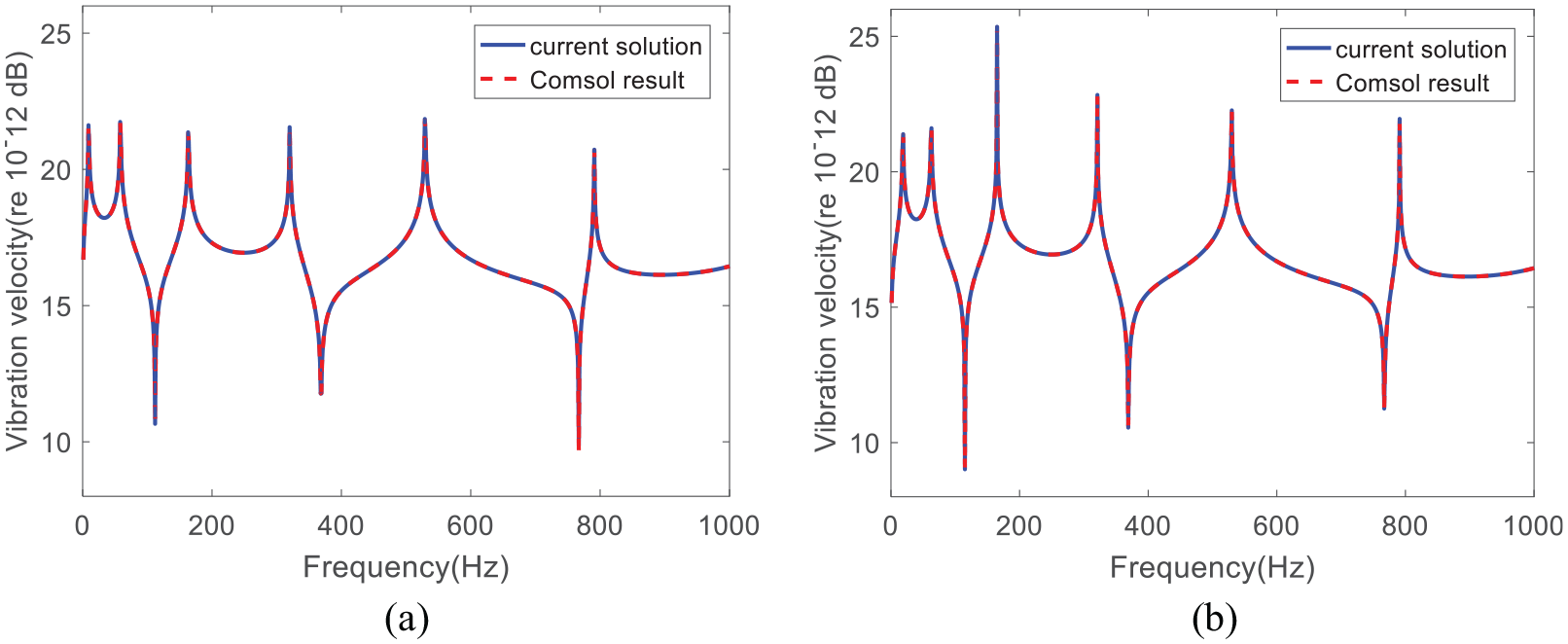
Vibration velocity response at 3L/5 of C-F beam calculated from the current model and FEM in COMSOL: (a)
Plotted in Figure 6 is the non-dimensional power flow transmission distribution across the whole beam including the elastic supporting foundation. During the subsequent study of power flow analysis of beam with various supporting conditions, since the modal frequency will be accordingly changed in this process, the power flow analysis corresponding to the fundamental modal frequency will be chosen for investigation. In Figure 6(a), a uniform elastic foundation with different supporting stiffnesses is taken into account, and it can be observed that variation of elastic stiffness of supporting foundation has a significant effect on the power flow transmission in the beam structure, especially in the supporting region [L/5, 3L/5]. Increasing the supporting stiffness of elastic foundation will cause a decrease of power flow distribution in the supporting part. Similar problem is also recalculated for different supporting stiffnesses with a non-uniform elastic foundation f(x) = 25(x/L – 0.4) 2 , and the results are presented in Figure 6(b). It can be found that the general influence trend is almost the same during the change of supporting stiffnesses. While with the introduction of non-uniform supporting stiffness in this foundation interval, the power flow transmission will become much complex, and some fluctuation phenomenon associated with power transmission during this foundation can be observed.

The non-dimensional power flow transmission distribution across the whole beam including the elastic supporting foundation defined in the interval [L/5, 3L/5]: (a) f(x) = 1; (b) f(x) = 25(x/L – 0.4) 2 .
For the power flow analysis, it represents the combined information of internal force and vibrational response in the whole beam. In the viewpoint of internal forces, the calculation of power flow in any filed point of beam structure actually involves two components, namely, translational shear force and rotational bending moment. With the aim to reveal the power flow mechanism under various supporting conditions, power flow transmission across the beam under the fundamental modal frequency is analyzed with various foundation stiffness distributions, and the results are presented in Figure 7 in which the elastic supporting foundation is defined in the interval [L/5, 3L/5]. It can be clearly seen that the introduction of external foundation supports will greatly affect the power flow distribution patterns. Different supporting conditions will mainly change the power flow component associated with the translational shear force at any field point in the beam. The sudden variation of total power flow in the support foundation is dominated by the shear force power flow component, which implies that the much more attention should be paid to shear force component with the aim to modify or attenuate the vibrational power flow transmission across the beam during the introduction of supporting foundation.

The non-dimensional power flow transmission across the whole beam due to translational shear force and rotational bending moment: (a)
Conclusion
In this article, transverse vibration characteristics and power flow analyses for an axially loaded beam with elastic edge supports and arbitrarily non-uniform foundation is modeled and investigated using energy principle in conjunction with Rayleigh–Ritz procedure. With the aim to make the admissible function sufficiently smooth across the whole beam, vibrational displacement field is expanded into a superposition of Fourier series and boundary smoothed auxiliary polynomials. Potential energy of beam with axial load and elastic foundation is formulated in system Lagrangian, which allows the analysis of current model through the minimization with respect to all the unknown coefficients. Moreover, Euler critical load is also studied for beams with elastic boundary and interval foundation.
Numerical examples are then given to validate the proposed model and study the vibration characteristics and dynamic behavior of axially loaded beam with various boundary condition and elastic foundation. Results show that the current model can make an accurate prediction of modal characteristics of such beam structure, and the axial load and elastic foundation has a significant influence on the beam vibration characteristics and critical load. Fundamental frequency will be zero when the compressive load is equal to the critical load. When the elastic foundation is in arbitrary non-uniform function, various coefficients of non-uniform elastic supports have great influence for the lower modal frequency. Moreover, the effects of axial load and elastic foundation will become weaker for the higher mode. Power flow analysis shows that supporting conditions will greatly affect the vibration energy transmission pattern, and the translational shear force plays a dominant role in this power flow transmission process. This work can shed some new lights on the systematic understanding of dynamic behavior of axially loaded beams with complex boundary conditions and general non-uniform foundation.
Footnotes
Handling Editor: James Baldwin
Declaration of conflicting interests
The author(s) declared no potential conflicts of interest with respect to the research, authorship, and/or publication of this article.
Funding
The author(s) disclosed receipt of the following financial support for the research, authorship, and/or publication of this article: This work was supported by the National Natural Science Foundation of China (Grant no. 11972125) and Fok Ying Tung Education Foundation (Grant no. 161049).