
Abstract
The splitter blade can effectively optimize pump performance, but there is still insufficient research in blood pumps that cover both hydraulic and hemolysis performance. Thus, the aim of this study was to investigate the effect of key factors related to splitter blade on the performance and flow field of axial flow blood pump. In this study, the number of splitter blades, the axial length, and the circumferential offset were chosen as three objects of study. An analysis of the flow field and performance of the pump by orthogonal array design using computational fluid mechanics was carried out. A set of hydraulic and particle image velocimetry experiments of the model pumps were performed. The result showed that the pump had greater hydraulic performance without sacrificing its hemolytic performance when it had two splitter blades, the axial length ratio was 0.6, and the circumferential offset was 15°. Based on these reference data, the splitter blade may contribute to greater hydraulic performance of the pump and cause no side effect on the velocity distribution of the flow field. This finding provides an effective method for the research, development, and application of structural improvement of the axial flow blood pump.
Introduction
Heart failure is one of the most serious diseases threatening human health. The blood pump is a microfluid machine that can be implanted in the human body. The blood pump is considered to have the potential to partially or completely replace failed hearts. Due to its complicated application condition, the blood pump, which is also the core engine for blood circulation in the artificial pump, still causes damage of blood by its flow field and threatens the patient’s health and safety. 1 Thus, the key to study of blood pump structure is to meet the pressure need of human blood circulation without causing excessive damage of blood.
The performance of blood pump can be mainly characterized by hydraulics and hemolysis. The shear stress existing in the flow field is the core factor causing hemolytic damage. 2 Being implantable, the blood pump has strict requirements for performance, whose optimization is the focus of research in this field.3,4 At present, computational fluid dynamics (CFD) has gradually matured in the analysis and evaluation of hydraulic and hemolytic performance of the blood pump in its development stage.5,6 Researchers combined CFD and experiment designs to study the state and performance of the flow fields of blood pumps with different structures, starting from details such as the gap, blade height, and blade shape. Although they have continuously optimized the performance of blood pump,7–10 there is room for further improvement.
Subtle adjustments in the pump design can have a critical impact on its performance, which is especially critical in the blood pump which is highly demanding on blood compatibility.11,12 The placement of splitter blade on the impeller is one of the key means to improve the performance of conventional pumps. The splitter blades, which act as auxiliary blades placed between the main blades, have been verified in the literature to improve the hydraulic performance and flow field stability of pumps,13,14 such as the miniature hydraulic pumps and double blade impeller pumps.15,16 Compared with conventional pumps, the blood pump needs adequate hemolytic performance to ensure safety, and the splitter blade is rarely studied in this field. The splitter blade structure has not been seen on any of the mainstream blood pump products such as HeartMate II, Jarvik 2015, and Incor.8,17 Further improvement of the pump performance can be made if the application and design of splitter blades are optimized. Thus, this study investigated the effect of the splitter blade and its relevant factors on the blood pump. The aim was to further improve the design and application of splitter blade, to the structural optimization of the blood pump.
This study investigated the effects of splitter blades and their key structural parameters on blood pump performance. The effects of core parameters on blood pump hydraulics and hemolysis performance were analyzed by orthogonal method and CFD simulation. A set of structural parameters that can optimize the performance of blood pump was obtained. The blood pump prototype before and after optimization was processed, and the performance level and flow field state of the blood pump with optimized splitter blade structure were analyzed by hydraulic experiment and particle image velocimetry (PIV) experiment. The results reveal the influence of the splitter blade and its structural parameters on the performance of the blood pump and demonstrate the potential of the splitter blade structure to optimize the performance of the blood pump.
Materials and methods
Blood pump
This study was conducted around a self-developed axial flow blood pump with helical blades. According to the requirement of human blood circulation, the target flow and pressure head of the pump was set at 5 L/min and 13.3 kPa. The main structure of the pump includes a front diffuser, an impeller, and a back diffuser. The blood pump relied on the impeller which rotates at a speed of 8000 r/min to generate the fluid energy required for blood circulation. As shown in Figure 1, the splitter blades of the axial flow blood pump were designed to be placed between every two main blades and were shorter auxiliary blades that had the same structure as the main blades. According to the structural characteristics of the splitter blades, three core factors including the number of blades, the axial length, and the circumferential offset were studied.
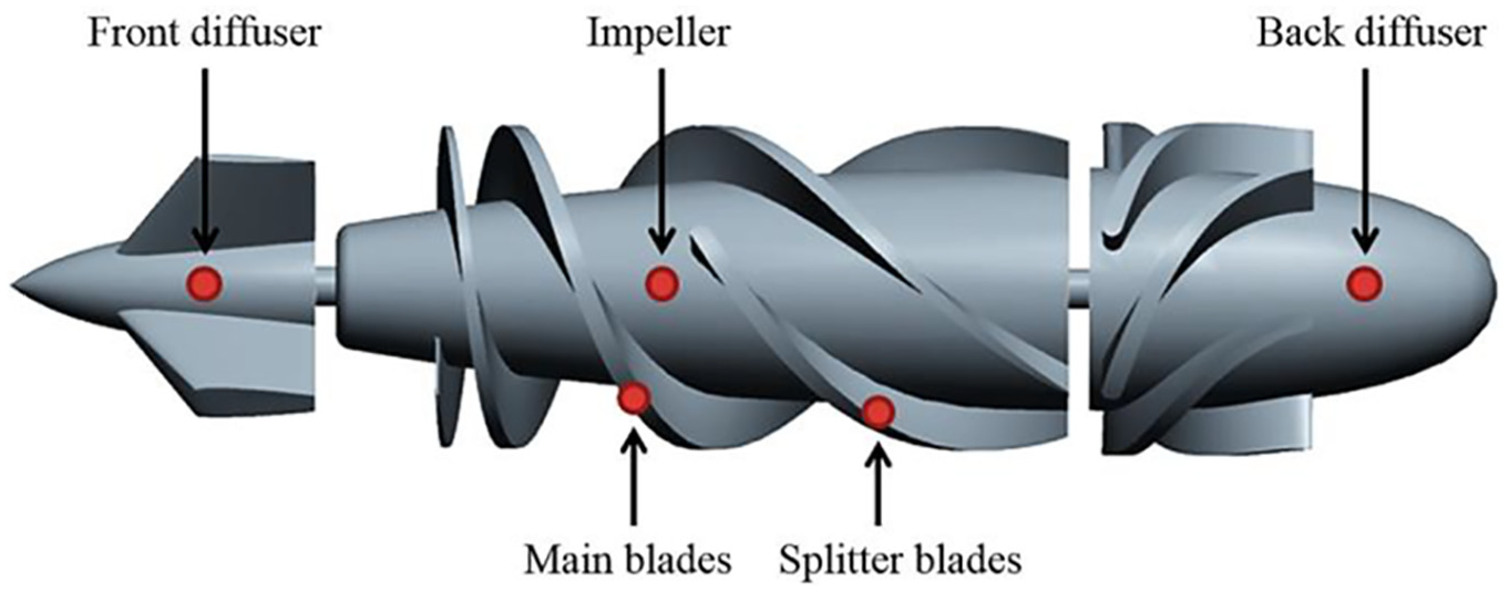
Internal structure of axial flow blood pump with helical blades.
Factor A: axial length of the splitter blade
The axial length of the splitter blade is represented by the ratio of the axial length of the splitter blade to that of the main blade. The larger the ratio, the longer the length of the splitter blade, and the more work the interventional flow field does. However, if the length ratio is too large, it may cause the flow passage inside the impeller to be blocked, resulting in a decrease in efficiency. According to the preliminary analysis, the four parameter levels of the axial length ratio of the splitter blade to the main blade are selected to be 0.4, 0.5, 0.6, and 0.7.
Factor B: splitter blade circumferential offset
Due to the circumferential uneven distribution of the velocity in the impeller flow passage, the splitter blade is appropriately offset from the back of the main blade by a certain angle at the intermediate position, which can improve the unstable flow state caused by the uneven flow of the main blade working face and the back surface. According to the preliminary analysis, the study selected four parameter levels of the splitter blades to the back of the main blades by −15°, 0°, 15° and 30°.
Factor C: number of split blades
The number of splitter blades is the key to the three structural parameters. The appropriate number of splitter blades can increase the impeller’s functional force and balance the flow separation between the main blades; however, the excessive number of blades can block the flow path and affect the hydraulic performance. According to the preliminary analysis, the two parameter levels of the number of splitting blades of 2 and 4 were selected and compared with the splitter-bladeless prototype.
Orthogonal array design
Orthogonal array design is an analysis method for multi-factor and multi-level objects. The orthogonal design considers the combination of factors and levels as a research node, and representative nodes can be selected for analysis through standard orthogonal tables, which can reveal the effect of various factors on performance, and help select the optimal structural parameter combination. According to the three-core structural parameters of the splitter blade, an L16 (2 × 42) mixed orthogonal research scheme was developed. Table 1 is a hybrid orthogonal research scheme based on a standard orthogonal table, which includes a total of 16 sets of different splitter blade structural parameter combinations.
Orthogonal array design.

CFD analysis
According to the orthogonal design, a three-dimensional model of blood pump corresponding to 16 sets of structural parameters was established, and a splitter-bladeless prototype was built for comparison. The hydraulic performance of each model and the hemolytic performance against blood damage were obtained by CFD. The calculations were performed using the commercial software ANSYS CFX 17.0 (ANSYS, Inc., Canonsburg, PA, USA). The ANSYS ICEM was used to establish the unstructured computational grid. Insufficient number of grids will reduce calculation accuracy, but too many grids will also cause a significant reduction in calculation efficiency. The grid number independence verification was carried out when the difference of the pressure head results was less than 2%. The number of grids is analyzed from 0.5 to 5 million. In this analysis, when the number of grids is more than 2.5 million, the calculation results change less than the set requirements. Therefore, the total number of computational grids was approximately 2.5 million. Furthermore, it was guaranteed that the established grid quality was above 0.45, and the minimum angle was greater than 20°, which was in line with the grid quality requirements of CFD calculation.
According to the medical literature, the medium blood density in CFD calculation was set at 1060 kg/m3, the viscosity was 3.5 mPa s, and the shear stress rate in the blood pump flow field was greater than 100 s−1. 18 Since the maximum flow velocity in the flow field was about 10 m/s and the average Reynolds number in the calculation region was above 104, the shear stress transport (SST) k–ω turbulence model was adopted. The turbulence model was generally considered to have better calculation accuracy for the blood pump.12,19 According to the requirements of the turbulence model, a boundary layer grid with y+ less than 2 was established. The impeller wall surface was rotating in the model at a speed of 8000 r/min, and the pump casing and the front and back diffusers had static wall surfaces, and the interface between the static and rotating surfaces was set by the frozen rotor. Through the boundary setting of the velocity inlet and pressure outlet, the pressure–velocity coupling equation was solved by the SIMPLEC algorithm, and the convergence precision reached 10−5.
Estimate of hemolysis
When blood flows through the blood pump, hemolytic damage occurs due to shear stress in the flow field. The hemolytic performance, which reflects the degree of damage, is the key to whether the blood pump functions well. The hemolytic experiment using real blood is susceptible to external influence and errors. In the blood pump research design, CFD is often used to conduct preliminary estimate analysis of hemolysis. 20
Although there are many factors affecting hemolysis, the shear stress and the exposure time of the cells under shear force are mainly considered in the hemolytic calculation of the blood pump. In this study, the shear stress of the flow field is calculated by equation (1) put forward by Bludszuweit21,22

Hemolytic calculation includes the shear stress and exposure time of red blood cells in the flow, and the flow field data obtained by CFD calculation. The corresponding hemolytic index is calculated by the empirical formula of hemolytic estimate.23,24 In total, 1000 random flowlines were selected from the flow field inlet, and such number will not result in difference of calculation results because of sufficient sampling. Hemolytic index was calculated through the classic hemolytic model raised by Giersiepen et al., 25 and the average of 1000 random flowlines was calculated as the hemolytic estimate result of the blood pump

where D represents the blood damage index and indicates a percentage of damaged red blood cells, where Hb is the total hemoglobin concentration, dHb is the released hemoglobin concentration, τ is the shear stress (Pa), and t is the exposure time (s) of the shear stress.
Experiment
The experimental prototype impeller was made of titanium alloy. An impeller of the optimized splitter blade structure and a splitter-bladeless prototype impeller for comparison were produced. The grade N48 NdFeB permanent magnets were embedded in the blood pump impellers and the alternating magnetic field was generated by the external magnetic drive device to realize rotation control. The maximum rotation speed could reach 10,000 r/min. Figure 2 shows the two sets of blood pump prototype impellers. The left picture shows the splitter-bladeless prototype impeller, and the right picture shows the impeller with optimized splitter blade structure that has been assembled with the front and back diffusers.

Blood pump prototypes: (a) prototype impeller without splitter blades and (b) blood pump prototype with optimized splitter blade structure that has been assembled with diffusers.
This study used hydraulic experiments to analyze the real performance of two different impeller structures and to verify the reliability of CFD results. Figure 3 is a set of hydraulic circulation experiment system of the blood pump, which consisted of a blood pump prototype, an external magnetic drive system, a pressure gauge, a flow meter, a regulating valve, an air release valve, a constant temperature water box, and various brackets and pipes. The experimental fluid used a 40% mixed solution of glycerin and water. At 20°C, the properties of the fluid enabled it to effectively replace blood to complete the measurement and analysis of the hydraulic performance of the experimental pump.27,28

The blood pump circulation experiment system.
The velocity distribution of the flow field of the blood pump prototype was obtained by PIV experiment. Because the hemolytic experiment of real blood was susceptible to a series of conditions, big differences could still occur even under the same experimental conditions. 20 Moreover, the hemolytic experiment could not analyze the shear damage of the flow field to the blood cells from the angle of internal flow field. Therefore, the PIV experiment was conducted to compare and analyze the velocity distribution of the flow field of blood pump prototype. From the perspective of microscopic flow, it could be determined whether the optimized splitter blade structure would generate additional hemolytic damage from shear force.
PIV is a transient, multi-point, non-contact hydrodynamic velocity measurement method. In the experiment, adequate tracer particles were injected into the circulation system, and the high-speed camera took two frames at a set time interval. The selected cross-frame time was 60 μs, and the state of the flow field was calculated by the displacement of the particles in the two frames. The PIV equipment used in the experiment was produced by TSI Company of the United States. The camera model of the equipment system was Zyla 5.5, and the highest sampling frequency was 100 Hz. The laser was a double pulse laser with a maximum energy of 100 mJ and a maximum frequency of 30 Hz. The PIV experiment could obtain accurate flow field measurements when the particle followability was high enough. 29 This experiment uses rhodamine fluorescent particles with a size of 7 μm and a density of 1.1 kg/m3, which followed the flow field very well. On the lens, a 560 nm high-pass filter was mounted to filter out the reflection of the metal surface of the impellers without affecting the shooting of the fluorescent particles.
Results
Results of orthogonal experiment scheme
The simulation calculation of CFD was completed for all the parameter models in the mixed orthogonal scheme in Table 1. The pressure head reflecting the hydraulic performance and the hemolytic index reflecting the hemolytic performance were obtained. Table 2 shows the calculation results of models in each group of the orthogonal scheme. Moreover, the comparative splitter-bladeless prototype had a calculated head of 12.71 kPa and a hemolytic index of 6.49 × 10⁻³. In the results, the pressure head of the No. 10 model was the highest at 13.51 kPa, indicating that the parameters of this model produced the best hydraulic circulation performance. However, the hemolytic index of the model reached 8.19 × 10⁻³, which was 26.2% higher than that of the splitter-bladeless prototype, which significantly reduced the hemolytic performance of the blood pump. The hemolytic index of the No. 2 model was the lowest at 6.48 × 10⁻³, which indicated that the blood pump had the least damage to the blood cells under this parameter combination. This index was close to that of the splitter-bladeless prototype and did not cause rise of hemolytic index. The head of the model reached 13.10 kPa, which was higher than that of the splitter-bladeless prototype, indicating better hydraulic performance.
Orthogonal numeration result.

In the orthogonal array design of Table 1, A, B, and C represent the three factors of axial length, circumferential offset, and number of the splitter blades, respectively. The results in Figure 4 reflect the effects of different factors and their levels on the head. The results in Figure 5 show their effects on hemolysis. Through the above calculation results, the influence of the core parameters of the splitter blades on the performance of the blood pump was analyzed.
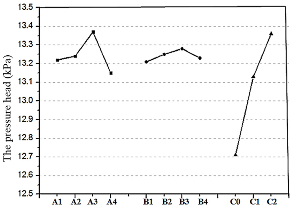
Relations between blood pump’s hydraulic head and multiple factors.

Relations between blood pump’s hemolytic estimate and multiple factors.
As for the number of splitter blades, the results showed that its effect on the blood pump hydraulic and hemolytic performance was significantly higher than the axial length and circumferential offset. When the number of splitter blades increased, the hydraulic performance of the blood pump increased while the hemolytic performance tended to decrease. Specifically, when the number of splitter blades was 2 and 4, the heads of the blood pumps were 0.42 and 0.64 kPa higher than that of the splitter-bladeless prototype, respectively. However, when the number of splitter blades was increased to 4, the hemolytic index of the blood pump was increased by 28.5% and 23.9%, respectively, compared with the splitter-bladeless prototype and the two-splitter-blade prototype, which caused a serious deterioration of the hemolytic performance of the blood pump. The average hemolytic value of the two-splitter-blade prototype had only about 5.0% difference compared with that of the splitter-bladeless prototype. Especially, for the No. 2 model with two splitter blades, 0.4 axial length ratio, and 0° circumferential offset, its hemolytic index was even slightly lower than that of the splitter-bladeless prototype.
As for the axial length of the splitter blade, the results showed that under different axial length ratios of the splitter blades to the main blade, the head tended to increase and then decrease in accordance with the length ratio. When the length ratio was increased 0.4 and 0.6, the head of the blood pump continued to rise by about 0.15 kPa, reaching a peak at a length ratio of 0.6. But as the length ratio continued to increase to 0.7, the pump head suddenly dropped by about 0.22 kPa. In the calculation result of hemolytic index, as the axial length of the splitter blades increased gradually, the hemolytic index of the blood pump rises to some extent. When the length ratio increased from 0.4 to 0.6, the hemolytic index only increased by less than 1.0%; when the length ratio increased from 0.4 to 0.7, the hemolytic index increased by 3.2%.
As for the circumferential offset of the splitter blades, the results from Figures 4 and 5 showed that between −15° and 30°, the hydraulic performance of the blood pump was the highest when the splitter blades were tilted 15° to the back of the main blade, and the average head was 12.28 kPa. Moreover, the hemolytic index was the lowest when the splitter blades were not tilted. When the splitter blades were tilted by 15° to each side, the hemolytic index increased by about 1.3%.
Based on the results of the orthogonal calculation, the three structural factors would affect the overall hydraulic and hemolytic performance of the blood pump as their parameters changed. When the axial length ratio and the circumferential offset of the splitter blades were 0.6 and 15°, the hydraulic performance of the blood pump could be improved without sacrificing its hemolytic performance. Among the three core factors, the number of splitter blades had the most significant impact on the performance of the blood pump. With the increase of the number of splitter blades, the hydraulic performance of the blood pump was on an obvious increase. However, when the number of splitter blades increased to 4, the average hemolytic index increased by more than 20%, which seriously deteriorated the hemolytic performance of the blood pump. In this regard, this study further analyzed the flow state of the internal flow field of the blood pump to explore the possible causes of the situation.
Results of the flow field analysis
In order to obtain the reason why the hemolytic index increased significantly as the number of splitter blades increased to 4, two groups of models whose axial length ratio and circumferential offset were both 0.6 and 15° but with two and four splitter blades, respectively, were established. CFD was used to analyze the flow field. Figure 6 shows the flow filed shear stress distribution of the axial sections at the front ends of the splitter blades of the two model impellers. The axial sections showed the similarities and differences of the shear stress distribution between the two models. From an overall perspective, the shear stress distributions in the flow fields of the two model impellers were both high in the middle and low in the two ends; the distribution and intensity of the shear stress in the front and rear parts of the impeller were basically the same, all below 100 Pa. The main difference between the flow fields of the two models was that the splitter blades gradually began to intervene in the middle of the flow field. The flow field shear stress of the four-splitter-blade model was significantly higher, reaching 228 Pa; and the maximum shear stress of the two-splitter-blade model was about 181 Pa, which was only 64.5% of the maximum shear stress of the four-splitter-blade model.
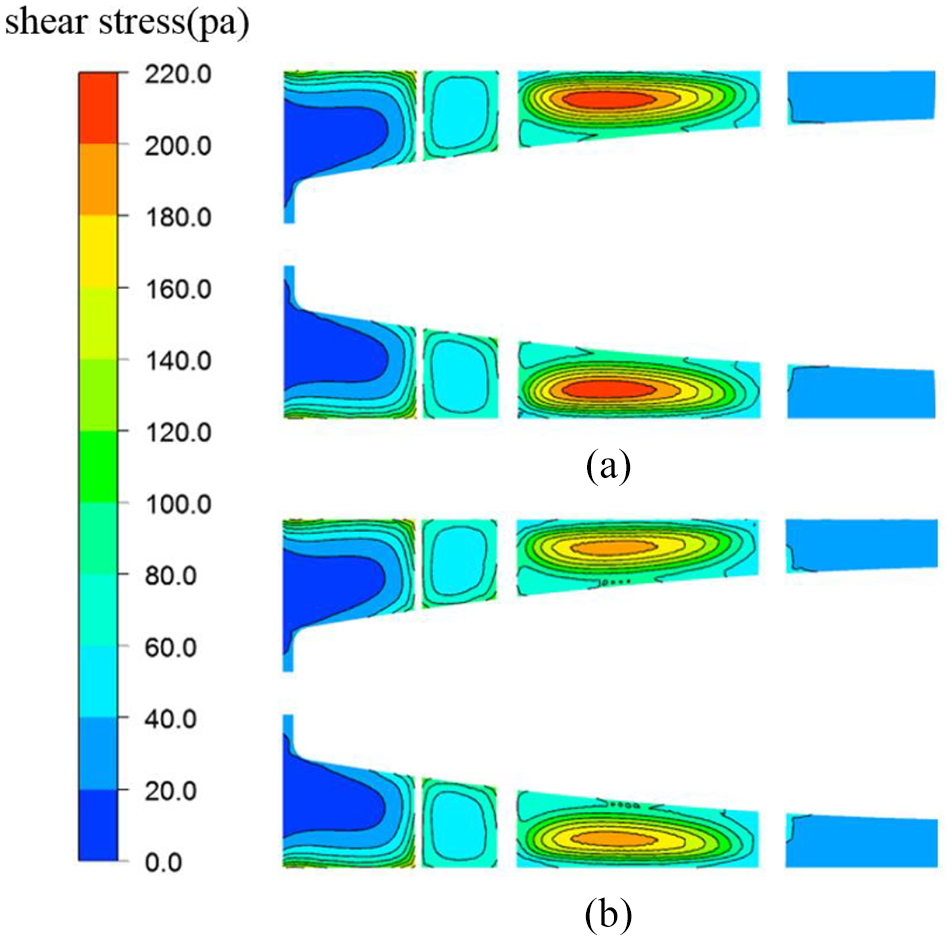
Results of shear stress distribution in the impeller area: (a) results of four-splitter-blade model and (b) results of two-splitter-blade model.
Figure 7 shows the velocity distribution of the radial sections of the two models at the front ends of the splitter blades, and the broken lines in the figure indicate the position of the axial sections as shown in Figure 6. The four-splitter-blade model had two main blades and four short splitter blades, and the flow cross-section was divided into six separate flow passages, whereas that of the two-splitter-blade model was divided into four separate flow paths. In the calculation results, the overall velocity gradually decreased from the axis to the walls. Among them, the velocity gradient of the flow field of the four-splitter-blade model was significantly larger, with the maximum velocity reaching 2 m/s, and the maximum velocity change in the flow passage was greater than 1 m/s. The maximum velocity change of the two-splitter-blade model in the flow passage was less than 0.5 m/s. The maximum velocity in a single flow passage of one model was even twice as large as that of the other model.

Velocity contour of the splitter blades inlet section: (a) four-splitter-blade model and (b) two-splitter-blade model.
Experiment results
Figure 8 shows the hydraulic experiment result of the splitter-bladeless prototype, and Figure 9 shows the hydraulic experiment result of the prototype with the optimized splitter blade structure. The hydraulic experiment obtained the corresponding hydraulic performance by measuring the pressure-flow curves of the prototypes at different rotation speeds. Each data point on the curve was the pressure head and flow rate of the prototypes at the corresponding rotation speed. From the hydraulic experiment results, the pressure and flow rate of the two sets of prototypes increased steadily with the increase of the speed of the blood pump impeller, and the variation tendencies were basically the same. For the experiment results of the set rotation speed of 8000 r/min, the hydraulic performance of the splitter-bladeless prototype was revealed by 12.75 kPa pressure head and 4.66 L/min flow rate, while the performance of the prototype with optimized splitter blades was improved to 13.19 kPa pressure head and 4.77 L/min flow rate. Comparing the hydraulic experiment and CFD calculation results, when the rotation speed was 8000 r/min, the performance of the prototypes was slightly lower than the CFD calculation results. The differences between experimental and calculated results of the two models in terms of flow rate and pressure head were about 5% and less than 1.0%, respectively.

Hydraulic experiment result of the splitter-bladeless prototype.
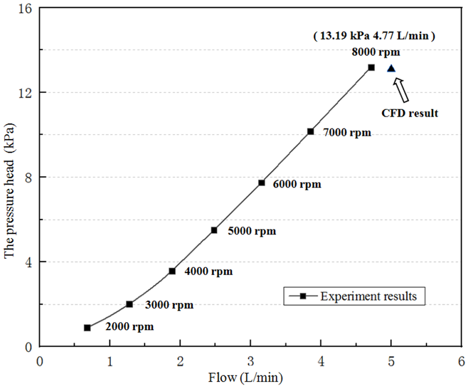
Hydraulic experiment result of the prototype with optimized parameters.
Figure 10 shows the results of the PIV experimental velocity field test. Because there was occultation when laser irradiated on the impeller and other components, the PIV experiment was conducted to shoot experiment of the blood pump axial section in Figure 6, and the dotted frame on the model diagram indicated the specific shooting position. Experiments were carried out on the flow field section to capture 200 sets of clear instantaneous flow field results. After the average calculation, the velocity distribution state of the position was obtained. From the PIV experiment results in Figure 10, the overall velocity field distribution of the two models was similar, and there was a maximum flow velocity of about 2.4 m/s in the middle and rear positions of the flow field, showing a distribution decreasing from the high-speed center to the periphery. Furthermore, there were two main differences between the experimental results of the two groups of models. First, the size of the 2.4–2.5 m/s high-speed zone of the two-splitter-blade model was slightly larger than that of the splitter-bladeless model, but their velocity and distribution at other locations were closed, and the velocity gradients of the overall flow fields were close. Second, the two-splitter-blade model had some unstable flow velocity distribution in the front flow field, while the splitter-bladeless model had a more uniform distribution. Overall, from the experiment results, the velocity range of the PIV experimental results of the two groups was basically the same, and the field distribution of the overall velocity was very close.
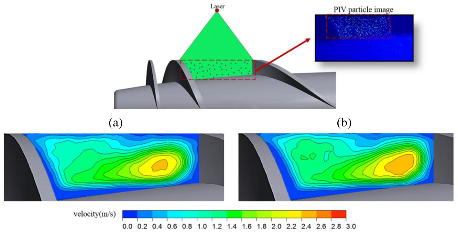
Result of PIV experiment: (a) result of splitter-bladeless model and (b) result of model with optimized splitter blades.
Discussion
In this study, we selected three key structural factors of the splitter blade, and obtained the hydraulic performance and hemolytic index by CFD calculation to reflect the performance of the blood pump under different splitter blade parameters, and obtained influence characteristics of the key factors of the splitter blade on the performance of the axial flow blood pump with the orthogonal design. The prototype axial flow blood pump without splitter blades had a calculated pressure head of 12.71 kPa and a hemolytic index of 6.49 × 10⁻³. There was a significant difference in blood pump performance under different splitter blade parameters in the orthogonal design (Table 2). Among them, the highest head reached 13.51 kPa and the lowest was 13.02 kPa, which was higher than that of the splitter-bladeless prototype blood pump. This showed that adding splitter blades on the impeller could improve the hydraulic performance of the blood pump, which was consistent with some research conclusions on traditional water pumps.13,15 However, the hemolytic index of each group reached a maximum of 8.48 × 10⁻³, which was much higher than that of the splitter-bladeless prototype pump, which meant that the splitter blades were likely to bring additional hemolytic damage. However, the No. 2 model in the orthogonal scheme had a head of 13.10 kPa and a hemolytic index of 6.48 × 10⁻³. The head of the model was higher than that of the splitter-bladeless model, and the hemolytic index was not improved. This indicated that under the appropriate splitter blade parameters, the hydraulic performance of the blood pump could be improved without affecting its hemolytic performance. The results of this study fully demonstrate the application potential of splitter blades in blood pump structure.
From the calculation results, the number of splitter blades is the key to the performance of the blood pump, and its influence on hydraulic and hemolytic performance is much greater than the axial length and the circumferential offset (Figures 4 and 5); in other studies on splitter blades, it is also believed that the number of blades is the key to affect performance of the pump. 13 For the blood pump in this study, when the number of splitter blades was increased to 2 and 4, the head of the pump was increased by 0.42 and 0.64 kPa compared with that of the splitter-bladeless prototype. The main reason is that increasing the number of splitter blades is equivalent to increasing the total length of the working blades on the impeller, thereby improving the overall functional force of the impeller. For other two factors, the axial length and the circumferential offset, their influence on the hydraulic performance was reflected in Figure 4 as rising first and then decreasing. The splitter blades had the maximum average head value when the length ratio was 0.6 but dropped to 0.22 kPa when the length ratio continued to increase to 0.7. The reason may be that the splitter blades at an appropriate length can increase the impeller’s working capacity of the flow, but excessively long splitter blades will cause the impeller flow channel to block, hence reduce the hydraulic performance of the impeller. Similarly, the splitter blades achieved the highest average head value at a circumferential offset of 15° because the splitter blades were tilted at a proper angle to the back of the main blade, to make the flow more stable and optimize its hydraulic performance. This pump had better flow state when the splitter blades were tilted 15° to the main blade. In addition, in terms of hemolytic index, the number of splitter blades also plays a dominant role in affecting it (Figure 5). When the number of splitter blades was 4, the hemolytic index of the splitter-bladeless model and the two-splitter-blade model increased by 28.5% and 23.9%, respectively. This reflects that the excessive number of splitter blades will seriously affect the hemolytic performance of the blood pump. When optimizing the hydraulic performance of the blood pump, it is necessary to ensure that the hemolytic index does not increase excessively. According to the analysis results of the orthogonal design, the number of splitter blades, axial length, and circumferential offset will affect the overall hydraulic performance and hemolytic performance of the blood pump to some extent. When the number of splitter blades was 2, the axial length ratio was 0.6, and the circumferential offset was 15°, the pressure head was raised from 12.71 to 13.28 kPa compared with the splitter-bladeless prototype blood pump. And the hemolytic index only increased by about 1%. It is considered that under this parameter, the hydraulic performance of the blood pump can be improved without substantially affecting its hemolytic performance.
The CFD analysis of the flow field was carried out around the problem that the hemolytic index of the blood pump increased largely after the number of the splitter blades increased to four. The number of splitter blades in the comparison models was 2 and 4, respectively, and other parameters were consistent. As revealed in the shear stress distribution of the impeller flow field cross-section at the front ends of splitter blades, the shear stress of the four-splitter-blade model in the middle of flow field was 26% higher than that of the splitter-bladeless model (Figure 6). Furthermore, it is generally considered that shear stress is the core factor causing erythrocyte hemolytic damage in blood pumps.3,5 Therefore, the splitter blade may have an impact on the area with high shear stress in the middle of the impeller flow field, and the design of four splitter blades will result in a higher hemolytic shear stresses in the middle of the impeller flow field and reduce the hemolytic performance of the blood pump as a whole. Furthermore, from the velocity distribution of the radial sections at the front ends of the splitter blades, the maximum velocity difference of the four-splitter-blade model in a single flow channel was more than twice that of the two-splitter-blade model (Figure 7). This may be attributed to the fact that the excessive number of splitter blades crowded the flow passage, and the effect of the splitter blades on the flow state was too large. In the study, the shear stress that generally caused hemolytic damage was mainly derived from the flow field velocity gradient, and the high-velocity gradient resulted in a higher shear stresses area, hence a higher hemolytic index.21,22,26
Through the hydraulic experiment, the splitter-bladeless prototype and the prototype with splitter blades of optimized parameters were tested. The performance variation trends of the two prototypes were similar. It is considered that the basic work characteristics of the impeller did not change after the splitter blades were added. When the rotation speed was 8000 r/min, the head of the prototype with splitter blades was increased by 0.44 kPa and the flow rate was increased by 0.11 L/min (Figures 8 and 9), indicating that adding splitter blades of optimized parameters on the impeller can improve the hydraulic performance of the blood pump to a certain extent. Compared with the experimental and CFD calculation results, the hydraulic performance test results of the prototype are slightly lower than the results of the CFD simulation, which may be attributed to the processing and assembly accuracy of the prototypes, but the gap is within acceptable limits. The PIV experiment tested the velocity field of the section in Figure 6. The purpose was to analyze whether the state of the flow field would be affected after adding the splitter blades. As a result, although the size of the high-speed zone of the model with splitter blades was slightly larger, the overall velocity range and the distribution state were basically the same, which did not have an additional effect on the velocity gradient (Figure 10). The difference in the above flow field should be due to the additional flow field of the splitter blades, but it does not fundamentally change the distribution state of the flow field. The size of the high-velocity zone and the slightly unstable flow state were also within an acceptable range; thus, it did not deteriorate the hemolytic performance of the blood pump as the four splitter blades did in CFD results.
Nonetheless, there were several limitations in this study. In this study, the analysis of hemolytic performance of the blood pump was done through CFD data, and no real blood was used in the experiments. This was mainly because the current prototypes have not fully met the requirements of blood experiments in terms of materials and surface treatment. And in some studies, the blood pump hemolytic experiment using real blood was susceptible to some factors, which masked the difference between different structural hemolytic indexes. 20 Furthermore, in the literacy about hemolytic performance of blood pump, hemolytic estimate by CFD was regarded as a common and reliable research method.7,9,30 In addition, the splitter blade structure in this study was mainly for the existing axial flow blood pump with spiral blades. The results of this study can be used to further promote the research into other different blood pump structures such as centrifugal ones.
Based on the CFD and experiment results, the effects of the splitter blade and its three key factors on the axial flow blood pump were obtained. A set of optimized structural parameters was proposed. This study provides an effective optimization method and design for the further study of the structure and performance of blood pump. The research results showed that the splitter blade with optimized parameters could improve the hydraulic performance of the blood pump without affecting its hemolytic performance and promote the further improvement and development of the blood pump impeller structure.
Conclusion
In this study, three key factors of the splitter blade structure, including the number of split blades, axial length, and circumferential offset, were selected. CFD experiment and orthogonal design were both employed to obtain the influence of these factors on the hydraulic and hemolytic performance of the pump. The results of the study suggested that when the number of splitter blades was 2, the axial length ratio was 0.6, and the circumferential offset was 15°, the hydraulic performance of the blood pump could be effectively improved without affecting its hemolytic performance. Furthermore, according to the research results, the blood pump prototype was processed. The hydraulic experiment and PIV experiment results showed that the optimized splitter blade structure could improve the hydraulic performance, without excessively affecting the velocity distribution state of the flow field. This study obtained the multi-parameter influence of the splitter blades on the performance of the axial flow blood pump and provided a set of optimized structural parameters. The results of this study provide an effective method and idea for the optimization of the blood pump structure. It is conducive to further advance the maturity and efficiency of the blood pump structure.
Footnotes
Handling Editor: James Baldwin
Declaration of conflicting interests
The author(s) declared no potential conflicts of interest with respect to the research, authorship, and/or publication of this article.
Funding
The author(s) disclosed receipt of the following financial support for the research, authorship, and/or publication of this article: This research was supported by the National Natural Science Foundation Project of China, grant numbers 51475477 and 31670999, and Postgraduate Independent Research and Innovative Project of Central South University, grant number 2018zzts021.