
Abstract
In this article, a fluid–solid coupling analysis of tripod sliding universal coupling and lubricating oil film was conducted by taking into consideration cavitation and thermal effects. The coupling of the sleeve and slip pin with the lubricant oil film under different pressure differences and frequencies was investigated. Moreover, the study results were compared with the results of fluid–solid coupling under the ideal condition of negligible cavitation and thermal effects. When considering these effects, the deformation and stress values of the sleeve and the slip pin gradually increase as the pressure difference and frequency increase. The deformation and stress values of the sleeve are reduced relative to the calculation results of fluid–solid coupling in ideal conditions. However, the values of the slip pin are increased. Furthermore, when considering the thermal effect, the deformation and stress differences for the sleeve and slip pin decrease as the pressure difference increases. The stress difference of the sleeve grows sharply, whereas the deformation difference of the slip pin increases only slightly as the frequency increases.
Keywords
Introduction
Westergaard 1 of the United States first proposed the fluid–solid coupling mechanism in 1933, but numerical simulation methods for fluid–solid coupling analysis were not established until 1980s with the rapid development of computer technology. The fluid–solid thermal coupling calculation in the mechanical field is implemented by establishing a data transfer relation among the pressure of the fluid, the deformation of the solid, and the heat conduction between the fluid and solid. Wodtke et al. 2 analyzed the thermal elasto-hydro lubrication performance of bearings and gears by means of this fluid–solid coupling technique. Xie et al. 3 applied fluid–solid coupling theory in an analysis of the micro-turbine. Lin et al. 4 studied the system lubrication performance of the sliding bearings with consideration of thermal and cavitation effects. Qin et al. 5 studied the fluid–solid thermal coupling model of the thrust bearings. Zhong et al. 6 analyzed the deformation and stress of the sliding bearings with consideration of oil-film lubrication by applying fluid–solid thermal coupling calculations. Guo et al. 7 studied and analyzed the static characteristics of the radial thrust ring bearing with consideration of the cavitation effect. Zhang et al. 8 solved the fluid–solid thermal coupling system of the bush-lubricant-journal of the radial bearing for the turbo generator. Zhu et al. 9 studied the deformation of the hydrostatic mechanical seal of the nuclear main pump in the context of fluid–solid thermal coupling. Lin et al. 10 analyzed the thermal fluid–solid three-field coupling results of sliding bearings at high speed.
The tripod sliding universal coupling is a novel drive mechanism. It is expected to be widely used in automotive industry because of its high transmission efficiency and strong transport capacity. The interaction and influence of the temperature and stress fields along with the lubricating oil flow field in the operation of tripod sliding universal coupling are key aspects of thermal fluid–solid multi-physical field coupling. Inspired by the study of fluid–solid thermal coupling in other contexts (such as bearings and turbines),11,12 this article analyzes fluid–solid thermal coupling in the context of coupling design. In the operation of tripod sliding universal coupling, the main transfer-component slip pin generates cavitation due to frequent cyclic movement, and the emergence of cavitation causes the oil-film flow field to change from single-phase flow to multiphase flow. Therefore, it is of essential practical significance to takes cavitation and thermal effects into consideration when studying fluid–solid tripod sliding universal coupling.
Basic theory of coupling analysis
Control equations of coupling
In general, fluid–solid coupling can be defined by a coupled equation that describes both the fluid domain and the solid domain. The unknown variables of the equation have the following two characteristics:
The fluid domain and the solid domain are interrelated and cannot be analyzed independently.
The independent variables describing fluid motion and those describing solid motion cannot be explicitly eliminated.
Fluid field control equations include the equations of mass conservation, momentum conservation, and energy conservation.
Mass conservation equation
The continuity equation of the fluid is based on mass conservation, that is to say, the increase in controlled-body internal mass equals to the mass inflow into the controlled body. Mass conservation is
where
Momentum conservation equation
According to the law of momentum conservation, the increase of the controlled-body internal momentum equals the inflow momentum plus the surface force impulse plus the volume force impulse. The differential form of the fluid motion equation is

where
By applying the generalized Newtonian viscosity law, the Newtonian viscous fluid momentum equation is expressed in terms of the velocity as follows

where
Energy conservation equation
The law of energy conservation specifies that the mechanical energy of a system plus the sum of all internal energies are equal to the total energy of the system, that is

where E is the internal energy of the system, Q is the external heat transfer to the system, and W is the work exerted on the system by the exterior.
The solid-field control equation of solid vibration and displacement induced by the fluid is as follows

where Ms is the mass matrix, Cs is the damping matrix, Ks is the stiffness matrix, r is the displacement of the solid, and τs is the stress that the solid bears.
At the fluid–solid coupling boundary, the most fundamental conservation principles for fluid and solid, namely, those involving the fluid stress

where the fluid-related variables are denoted by the subscript f, and the solid-related variables are represented by the subscript s.
Three-dimensional model and meshing
This study employs Pro/Engineer, the three-dimension software of American Parametric Technology Company (PTC), to carry out the construction of the model for tripod sliding universal coupling. 13 The fluid–solid coupling of the tripod sleeve and slip pin portion together is incorporated into the model of the fluid field. The fluid field consists of the lubricating oil film, and its model should be completely consistent with the sleeve and the slip pin, as shown in Figure 1.

Three-dimensional diagram of tripod sliding universal joint and lubricant film: (a) tripod sliding universal joint and (b) lubricant film.
Since the oil film between the tripod sleeve and the slip pin in the universal coupling is very thin, the thin-wall thickness does not exceed 1 μm, and the ratio of the oil-film length to the thin-wall dimension is too large, which complicates the meshing process. The conventional tetrahedral mesh is of low quality and susceptible to divergence. Therefore, the octree algorithm in ICEM with suitable robustness is used in the establishment of the unstructured grid, 14 as shown in Figure 2(a).

Lubricant film mesh: (a) unstructured mesh and (b) polyhedron mesh.
A non-structured mesh has satisfactory adaptability, which is beneficial to the meshing of complex regions, but the production speed of non-structured mesh is slow, and the data interaction time is long. Thus, the introduction of an unstructured mesh of ICEM into FLUENT for solution may result in a large stretch ratio of the mesh. Under this scenario, the computational accuracy of the unstructured mesh is challenging to ensure, and substantial computer memory and computational time are consumed. Therefore, it is necessary to convert the unstructured mesh into a polyhedral mesh, as shown in Figure 2(b).
Boundary conditions and physical properties
Set the flow field equal to the uncompressible flow field. Apply the SIMPLE algorithm, and choose the k-ε turbulence model and second-order upwind algorithm to calculate the solution. 15 The lubricant is P100 lubricant oil. The material properties of the tripod sleeve and slip pin are shown in Table 1, and the characteristics of the lubricating oil are shown in Table 2.
Material attributes.

Characteristics of P100 lubricating oil at 295 K (temperature).

Fluid–solid coupling with consideration of the cavitation effect
For flowing liquid, if the pressure is lower than that of the air separation pressure at that specific liquid temperature, gas can separate from the liquid in which it was originally dissolved. As a result, the liquid fills with a large number of bubbles, causing the liquid flow to be discontinuous, or exhibiting so-called cavitation.16,17 In the coupling process, cavities are inevitably produced, altering the behavior of the oil-film flow field from single-phase flow to multiphase flow. Full consideration of the cavitation effect is of great significance in the study of the flow field characteristics of coupling. Hence, the cavitation model is incorporated into the ideal oil-film model.
In this article, the cavitation simulation of the tripod sliding universal coupling applies the Singhal model. 18 The Singhal model uses mass transport equation to simulate the mass transfer between liquid and steam, coupled with multiphase flow model, and calculates the two-phase flow field. The Singhal model satisfies the following equation according to the application principle of the model

where


where
Parameters with subscript l denote the liquid-phase component, and those with subscript v denote the gas-phase component.
Coupling results under various pressure differences
Sleeve
Figure 3 shows the deformation contour plot of the sleeve along with a comparative line graph of the sleeve deformation with and without cavitation. Figure 3 reveals that the overall deformation of the sleeve is slightly less with cavitation relative to the one without cavitation because the coupling surface of the sleeve and oil film is the oil-film outer wall and because the oil-film outer-wall pressure under the cavitation model is slightly less than that without cavitation. Therefore, the overall deformation of the sleeve is reduced when cavitation is taken into account. The line graphs are analyzed in terms of the deformation for various pressure differences with and without cavitation. Note that the numerical difference is not large in the case of a low-pressure difference with or without cavitation. As the pressure difference increases, although the overall deformation of the sleeve still tends to increase, the deformation difference changes from nearly zero to gradually becoming larger with or without cavitation.

(a) One of sleeve deformation contours under various pressure differences and (b) variation of sleeve deformation with differential pressure.
Figure 4 shows the stress contour plot of the sleeve along with the comparative line graphs of the stress values for the sleeve with and without cavitation. The quivalent stress of the sleeve with cavitation is smaller. A comparison of the stress changes of the sleeve for various pressure differences with or without cavitation indicates that as the pressure difference increases, the overall stress of the sleeve continues to gradually increase. Relative to the steady variable rate without the cavitation model; however, the one with the cavitation model fluctuates significantly.
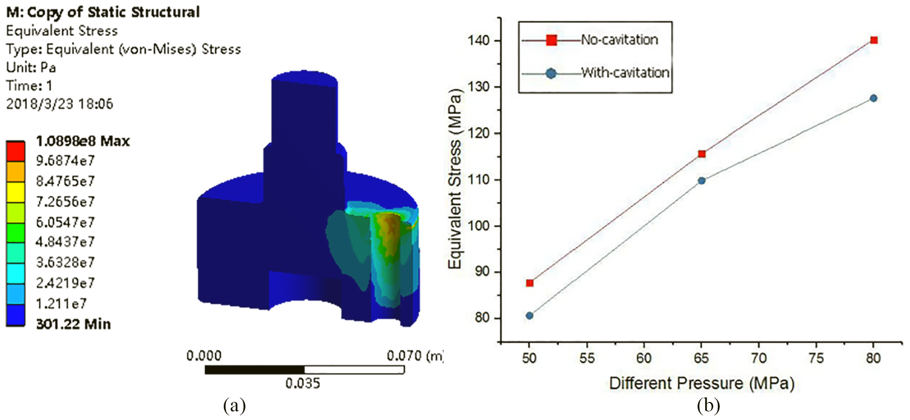
(a) One of sleeve stress contours under various pressure differences and (b) variation of sleeve stress with differential pressure.
Slip pin
After simulating calculation, the slip pin deformation diagram and deformation comparison line graphs are obtained (Figure 5). Since the slip pin is coupled to the inner wall of the oil film, the inner wall pressure of the oil film with cavitation is greater than that without cavitation. Therefore, the deformation of the slip pin with cavitation is greater than that without cavitation. Although the deformation of the sleeve increases as the pressure difference increases with or without cavitation, the deformation growth change rate is relatively steady in the case with cavitation. Since the deformation of the slip pin is much greater than that of the sleeve, the oil-film thickness between the slip pin and the sleeve is reduced, which makes the oil-film susceptible to breakage and dry friction at this place. In addition, the friction and wear of the tripod sliding universal coupling is aggravated, affecting its service life.

(a) One of slip pin deformation contours under various pressure differences and (b) variation of slip pin deformation with differential pressure.
Figure 6 describes the stress contour plot and stress comparison line graphs of the slip pin under various pressure differences. With the cavitation effect taken into account, the maximum stress outcome of the slip pin coupling with the oil-film inner wall is greater than that without considering cavitation. As the pressure difference increases, the slip pin stress also increases, but the variation in the stress value becomes more significant in the case of cavitation. This finding indicates that the presence of cavitation has a detectable influence on the stress–strain value of the slip pin, and the stress concentration problem is aggravated. To prevent tripod sliding universal coupling system from premature wear failure, the induction of cavitation should be taken into consideration, or the universal coupling should be redesigned with a focus on the stress concentration problem.

(a) One of slip pin stress contours under various pressure differences and (b) variation of slip pin stress with differential pressure.
Coupling results under different frequencies
Sleeve
Figure 7 gives the sleeve deformation contour plot and a comparison of the sleeve deformation under different frequencies. When cavitation is incorporated, the deformation change rate first increases and then decreases, followed by an increase. The deformation rate does not include the last increase under the no-cavitation condition. This result indicates that the existence of cavitation has a detectable impact on the sleeve deformation. While the deformation increases with increasing frequency, the deformation with cavitation is slightly less than that without cavitation because the outer wall pressure of the oil film, which acts as a coupling surface, is smaller under the cavitation condition. Thus, the coupling result is smaller. As shown in the fold line comparison chart, this variation is very small. However, since the oil-film thickness is typically less than 1 µm, this deformation cannot be neglected.
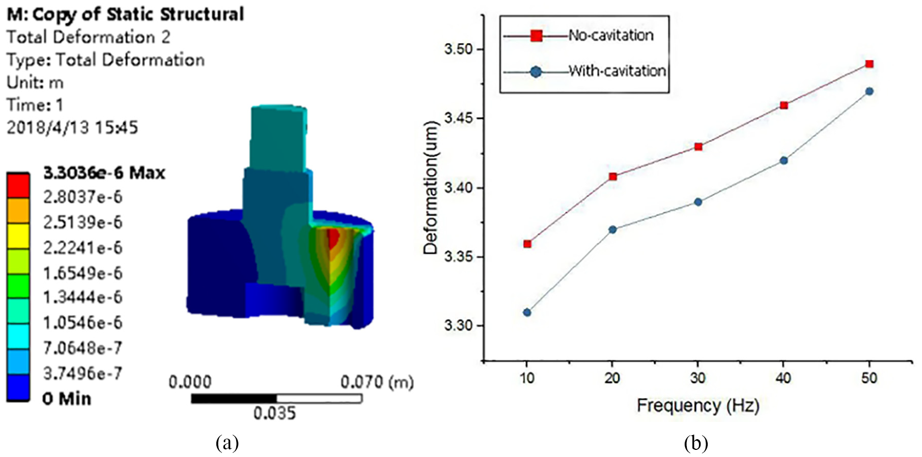
(a) One of sleeve deformation contours under various different frequencies and (b) variation of sleeve deformation with different frequencies.
Figure 8 shows the sleeve stress contour plot and a comparison of the sleeve stress under different frequencies. The stress increases as the frequency increases. The stress without cavitation is slightly higher than the stress with cavitation. However, the higher the frequency, the smaller the difference between the equivalent stress with and without cavitation. Moreover, the change rate of the overall stress without cavitation always increases first and then decreases, followed by an increase. In particular, when the frequency is higher than 40 Hz, the stress increases sharply, and the possibility of a stress concentration also increases.

(a) One of sleeve stress contours under different frequencies and (b) variation of sleeve stress with different frequencies.
Slip pin
Using the inner wall of oil film as coupling surface to form fluid–solid coupling with the slip pin, the slip pin deformation contour and comparison diagram with different frequencies, as shown in Figure 9, are obtained. As the frequency increases, the overall slip pin deformation gradually increases. The deformation with cavitation is higher than that without cavitation. The differences relative to the sleeve are as follows: as the frequency increases, the difference in sleeve deformation between the two cases gradually decreases, while the difference in slip pin deformation between the cases is very significant. The change rate of the slip pin deformation is quite stable and exhibits only a small difference. The difference at higher frequencies is larger.

(a) One of slip pin deformation contours under different frequencies and (b) variation of slip pin deformation with different frequencies.
Figure 10 shows the slip pin stress contour plot and line graph of the slip pin under different frequencies. The stress of the slip pin is distributed symmetrically, and the overall stress of the slip pin shows an increasing trend as the frequency increases. The stress of the slip pin with cavitation is greater than that without cavitation. In addition, the stress change rate with cavitation first decreases and then increases. It can be found by observing the stress difference with and without cavitation that the stress difference is almost constant when the frequency is relatively low. As the frequency increases, the stress change rate with cavitation increases, while that without cavitation decreases. Thus, the change in the stress difference is significant.
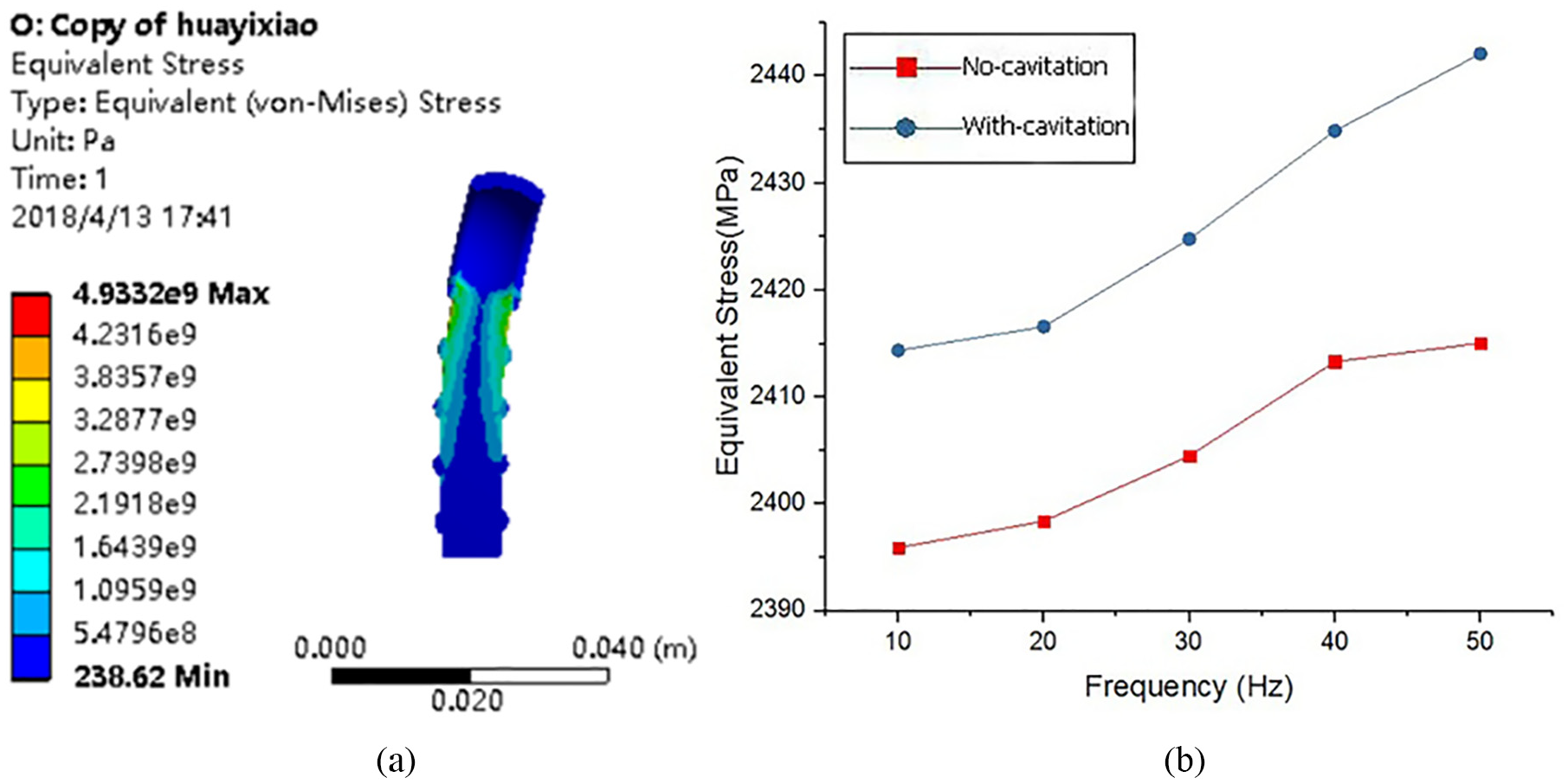
(a) One of slip pin stress contours under different frequencies and (b) variation of slip pin stress with different frequencies.
Fluid–solid coupling with consideration of thermal effects
Fluid–solid thermal coupling is generated based on fluid–solid coupling. In other words, fluid–solid coupling (without considering the temperature field) is a simplified form of fluid–solid thermal coupling.19,20 For real fluid–solid thermal coupling problems, the deformation of the solid induced by thermal effects and fluid pressures must be included as well as the change in the temperature field induced by the solid-field deformation and the flow of the fluid. Moreover, the impact of the change in fluid physical properties and fluid pressure should be studied which is induced by the solid deformation and the thermal effect on the fluid flow characteristics.
Coupling results under different pressure differences
Figures 11 and 12 show, respectively, the deformation and stress of the sleeve under various pressure differences; Figures 13 and 14 show, respectively, the deformation and stress of the slip pin under the same pressure differences. When other conditions are fixed, the deformation and stress of the fluid–solid thermal coupling are greater than those of the fluid–solid coupling. As the pressure difference increases, the thermal deformation and thermal stress of the sleeve and slip pin increase. A larger pressure difference corresponds to a smaller difference between the fluid–solid coupling and fluid–solid thermal coupling because the increase of pressure difference causes the flow rate of the lubricating oil to increase. When the fluidity of the lubricating oil increases, the heat removed by the lubricating oil increases accordingly. Thus, the temperature rise decreases as the differential pressure increases. The thermal stress and thermal deformation caused by the thermal effect also decrease. So appropriately increasing the pressure difference is beneficial to suppress the temperature rise and ensure the thermal stability of the coupling. However, an increase in the pressure difference induces an increase in the fluid pressure and a further increase in the deformation and stress of the sleeve and slip pin. Thus, although the temperature increase is reduced, the transported heat is also limited since the lubricant oil-film thickness is thin and the flow rate is limited. Therefore, as the pressure difference increases, the deformation and stress of the sleeve and the slip pin still show an overall increasing trend. However, the rate of increase is lower than that when the thermal effect is not considered.

(a) One of sleeve deformation contours under various pressure differences and (b) variation of sleeve deformation with differential pressure.
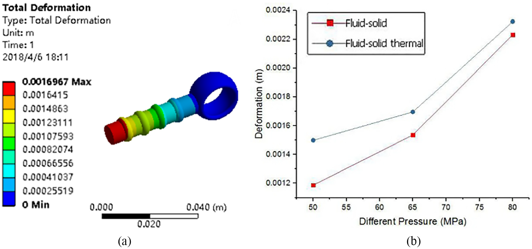
(a) One of slip pin deformation contours under various pressure differences and (b) variation of slip pin deformation with differential pressure.

(a) One of sleeve stress contours under various pressure differences and (b) variation of sleeve stress with differential pressure.

(a) One of slip pin stress contours under various pressure differences and (b) variation of slip pin stress with differential pressure.
Coupling results under various frequencies
Figures 15 and 16 show variations of sleeve and slip pin deformation to stress. As the frequency increases, the deformation and stress of the sleeve and the slip pin also increase when the thermal effect is taken into account. Moreover, the fluid–solid thermal coupling results of the sleeve and the slip pin are significantly greater than those in fluid–solid coupling because the heat generated by the temperature field increases with increasing frequency. While the injection speed of cold oil increases as the coupling frequency increases, the temperature decreases due to the mixture of cold oil and the in-operation hot oil is within the high-temperature range. The maximum temperature still shows a gradually increasing trend. The temperature increase results in uneven lubricant oil viscosity, which in turn affects the coupling thermal stability. Thus, a suitable frequency should be set during the design of the coupling, and targeted cooling measures should be applied. The change rates of tripod sleeve deformation in fluid–solid thermal coupling and in fluid–solid coupling are similar, and the difference in stress increases prominently with increasing frequency. On the contrary, the difference in the slip pin deformation gradually increases as the frequency increases, and the difference in stress decreases with increasing frequency. But the decrease is relatively small.

Sleeve comparison under various frequencies: (a) deformation and (b) stress.

Slip pin comparison under various frequencies: (a) deformation and (b) stress.
Conclusion
When the cavitation effect is considered, along with an increasing pressure difference and frequency, the deformation and stress of both the sleeve and slip pin increase.
When the thermal effect is considered, the deformation and stress of the sleeve and slip pin both increase with increasing pressure difference and frequency.
When the cavitation effect is considered, the deformation and stress of the sleeve are less than that without considering cavitation, and the deformation and stress of the slip pin are greater than that without considering cavitation. Moreover, the change in the difference in deformation and stress of the slip pin is larger than that of the sleeve.
The deformation and stress of the sleeve and the slip pin of the fluid–solid thermal coupling analysis are greater than that in the fluid–solid coupling analysis, and the differences in thermal deformation and thermal stress of the sleeve and the slip pin gradually decrease as the pressure difference increases. The difference in the rate of change of the sleeve deformation of the fluid–solid thermal coupling and fluid–solid coupling under different frequencies is similar, and the difference in stress increases substantially as the frequency increases. The differences in slip pin deformation gradually increase as the frequency increases, while the differences in stress decrease slightly.
Footnotes
Appendix 1
Handling Editor: James Baldwin
Declaration of conflicting interests
The author(s) declared no potential conflicts of interest with respect to the research, authorship, and/or publication of this article.
Funding
The author(s) disclosed receipt of the following financial support for the research, authorship, and/or publication of this article: This paper was supported by Shandong Provincial Key Research and Development Program (grant no. 2018GGX103015).