
Abstract
In order to study fretting wear damage law of planetary frame axle hole, the distribution of normal stress and relative sliding velocity at axle hole was obtained by finite element software, and a method of extracting fretting wear characteristic parameter data was put forward and verified. According to the modified model of fretting wear depth calculation, the wear depth of each step at axle hole was calculated, and the influence of interference on wear depth was analyzed. The results show that the stress distribution obtained by this method corresponds to the values of each node in the Workbench stress nephogram at that time and has the same distribution rule, which shows that the method is correct. The stress concentration near the inner part of the axle hole of the planetary frame is obvious. Along the circumferential and axial direction of the shaft hole, the relative slip velocity of both ends is larger, and the relative slip velocity of the middle part is smaller. Average wear in both axial and circumferential directions increases with the increase in interference, while wear in the axial direction plays a dominant role in the whole meshing process.
Planetary gear reducer is widely used. As the power output terminal, planetary carrier has better load-bearing performance, higher hardness of tooth surface, high reliability, and high transmission efficiency, 1 but it has a high failure rate in the process it is being used. The interference fit is often used between the planetary frame and the planetary wheel axle. The elastic deformation between the fittings is different. Affected by the internal and external excitations, there will be relatively small fretting amplitude of relative reciprocating slip at the joints, which leads to fretting wear between the contact surfaces. Finally, the fatigue life of the planetary frame decreases as a whole. 2
Engineers and technicians carried out experiments on a fretting fatigue/fretting wear tester to obtain the influence of parameters such as positive pressure and relative slip amplitude between contact pairs on the friction damage of the contact surface.3–6 Because it is difficult to measure the basic parameters of fretting wear, such as normal pressure and relative slip between contact pairs, the finite element method (FEM) has been applied more and more to the study of fretting wear.7–9 Kim and Roschke 10 carried out a finite element simulation analysis of metal friction pairs with swing contact, discretized the continuous wear process, compared the experimental and simulation results, and proved that the simulation method can well simulate the wear process of the material surface. Cruzado et al. simulated and analyzed the fretting wear of wire rope, and discussed in detail how to discretize the mesh of the model and adjust the step size of the nodes, which improved the calculation efficiency. The feasibility of the simulation method was proved by experiments.11,12
YB Gong et al. studied the interference structure of hollow axle based on Archard’s wear calculation model. Through finite element analysis, the influence of contact pressure, friction shear stress, and slip distance on fretting wear was obtained. 13 XL Yang et al. established the motion equation of particles in fretting wear and obtained a new method for calculating the wear rate. Taking the friction system composed of magnesium and iron as the research object, the influence of positive load pressure on the wear rate was analyzed, but the calculation was complicated. 14 YQ Tan et al. 15 analyzed the fretting friction contact behavior of involute spline pairs by the FEM, obtained the distribution law of contact pressure and relative slip, analyzed the fretting friction contact state, found the rule of influence of the friction factor and load on Ruiz parameters, but could not quantitatively describe the rule of influence of the friction factor and load on Ruiz parameters. HJ Zhang et al. established a two-dimensional cylindrical-plane fretting wear model. The influence of cylindrical radius, elastic modulus of cylindrical material, and Poisson’s ratio on the plane wear profile was analyzed from the wear width and depth of the plane. The influence of other components in the assembly was neglected. 16 YB Zhang et al. 17 established the fretting wear calculation model of interference structure and found that the contact pressure at the fitting edge is the largest. Because fretting wear reduces the stress concentration, the fatigue life was prolonged. 18 GH Jia et al. 19 studied the influence of interference on fretting wear of a gear shaft shoulder. To sum up, the effect of interference on fretting wear of the planet carrier shaft hole interference fit structure needs further study.
A method for extracting the data of finite element analysis is presented in this article. The influence of normal stress and relative slip velocity on fretting wear at a substep of the planetary frame shaft hole is obtained. The fretting wear depth is calculated and the influence of interference on fretting wear depth is analyzed.
Calculation model of fretting wear depth
British professor Archard put forward the wear equation. 20 Based on this equation, a modified model is derived for calculating the wear depth of a joint’s wear surface as follows

where m is the total incremental step in the finite element analysis (m = 50); tk is the time corresponding to the Kth substep; K is the wear coefficient (K=1×10⁻⁴); 20 H is Brinell hardness and σy = H/3 in elastic materials; σk and σk+ 1 are the corresponding positive pressure of the contact surface of a node at the k and k+ 1 incremental steps, respectively; vslip is the relative slip velocity between contact pairs (unit: m/s); and σk, σk+ 1, and vslip are obtained from the simulation analysis.
Data extraction method of fretting wear characteristic parameters
It is impossible to obtain the parameters that affect fretting wear directly in the result file in the Workbench software. In order to obtain the magnitude of the variables corresponding to each finite element node under a certain load step, a data extraction method and a program are proposed based on ANSYS Workbench and APDL combined simulation and MATLAB processing technology.
Twice coordinate transformation of characteristic parameters
In order to evaluate the fretting wear damage of planetary gear train axle holes, it is necessary to obtain the analysis and calculation results of the Workbench finite element software. The planetary wheel itself rotates around the planetary axis and at the same time rotates around the solar wheel in the planetary gear system. It is difficult to confirm the position relationship between the components. The finite element software works in the global Cartesian coordinate system. When establishing the dynamic model of a planetary gear train, the following coordinate system is created on the planetary frame, which makes the planetary gear train change from epicyclic gear train to fixed-axis gear train, and reduces the difficulty of dynamic analysis. Therefore, in order to simply represent the displacement, velocity, acceleration, and other motion parameters of each component of planetary gear train in the generalized coordinate system, coordinate transformation is needed. As shown in Figure 1, in the global Cartesian coordinate system, the unit components of each coordinate axis are expressed as xs, ys. The unit component of each coordinate axis is expressed as xc, yc, wc in the following coordinate system of the planetary frame. wc represents the angular velocity of the following coordinate system of the planetary frame in the global Cartesian coordinate system. The angle between xs and xc is θ, where θ = wc·t.

Coordinate transformation schematic.
According to the geometric relationship of the planetary gear train mechanism in the figure, the coordinates in the following coordinate system are

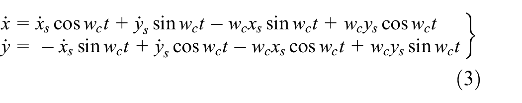
The first-order derivative of equation (2) leads to the expression of velocity in the global Cartesian coordinate system in the follower coordinate system as follows
When extracting the data of planetary gear train, because each part of planetary gear train belongs to the rotating component of axis, the global Cartesian coordinate system is transformed into a polar coordinate system to facilitate the extraction of node data on the circumferential cylindrical surface of the axis and reduce the difficulty of subsequent data extraction. In polar coordinates, the position of a point in a plane is determined by the distance r from the point to the origin of the coordinate and the angle θ between r and the x-axis in the coordinate system. The coordinate transformation relationship of the Cartesian coordinate system in the polar coordinate system is shown in Figure 2.

Coordinate transformation relations of rectangular coordinates in polar coordinates.
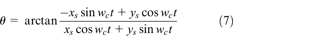
The mathematical relations of polar coordinates can also be expressed in Cartesian coordinates as follows


The displacement in the circumferential direction is given as

Axial slip velocity is given as

Thus, the mathematical relationship between velocity and displacement in the global Cartesian coordinate system and the following polar coordinate system is established.
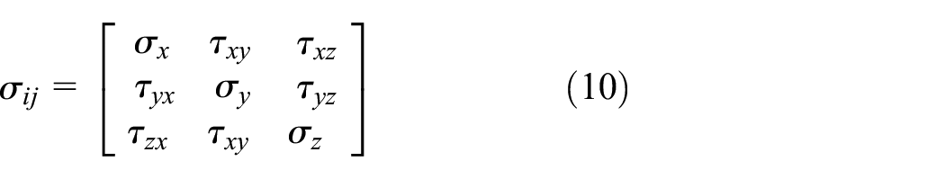
A three-dimensional cylindrical coordinate system can be formed by extending the polar coordinate system in the direction of the z-axis perpendicular to the plane of graph (equation (2)). It is assumed that the size of the object on the z-axis is a unit length. According to the knowledge of elastic–plastic mechanics, the stress state in an object is determined by nine stress components on three differential planes perpendicular to the x-, y-, and z-axes through the point, that is
When each coordinate system rotates at a certain angle, the component of stress tensor will change, but the stress state of the point will not change with the rotation of the coordinate system. The component of stress in the new coordinate system is

In order to establish the mathematical relationship between the two coordinate systems, the direction cosines of the angles between the old and new coordinate systems are set up as shown in Table 1.
Directional cosine of angles between the new and old coordinate systems.

A differential plane perpendicular to the x′-axis is made at a certain point. The stress vector on this differential plane is denoted as Fx′. The normal stress on the differential plane perpendicular to each coordinate axis can be obtained by projecting the stress vector Fx′ to the x′-axis as follows

The stress components on the differential plane with normal direction y′-axis, z′-axis, can, respectively, be obtained as follows


In particular, in plane coordinates, if the angle between the y′-axis and y-axis coordinates is θ, the relationship between the angle between the old and the new coordinates is shown in Table 2.
Angular relations between the old and new coordinates.

The slip velocity and normal stress of two contacts at the corresponding time points of each loading step can be obtained in transient dynamic analysis, but the fretting wear cannot be acquired directly at a certain loading step. Based on the above conversion relationship, the program of the APDL reading result file converts the analysis results in the Cartesian coordinate system to the following cylindrical coordinate system for calculation and then extracts the calculation results of each node in the cylindrical coordinate system.
Data extraction method of characteristic parameters
In order to implement APDL to deal with the data of the Workbench software post-processing, it is necessary to solve the problem of interface docking. After simulation and analysis of the model by Workbench, the corresponding path is found. The *.rst file in the path is the corresponding result file, and the program of reading the result file by APDL is written. The program flowchart of the APDL reading result file is shown in Figure 3. Because of the large number of program codes, the description in detail is not given. The method of extracting the upper node data from the contact of the shaft hole is to assume that the circumference of the shaft hole is expanded into a rectangular plane. The special meshing guarantees that the regular arrangement of the number of rectangular square nodes is ensured, which facilitates the processing of node data after programming.

The program flowchart of the APDL reading result file.
The general idea of the whole program is as follows: read the result file, create array variables, extract and store the result data in the array variables, create the txt result storage file, and write out the results. The entire command stream program is stored in the root directory of the corresponding result file path in the form of a text file. Start the ANSYS software, read the command stream file, and execute the relevant data extraction program. This avoids the tedious manual interactive interface data extraction method and greatly improves the efficiency of data processing. Finally, the data processing program of MATLAB is compiled to process the data in batches, which realizes the visualization operation of data. The distribution rules of the normal stress and relative slip velocity of the contact surface are studied, and the influence of interference on fretting wear depth is analyzed.
Finite element geometric model and pretreatment
The center wheel acts as the input axis to transfer the power to the planetary gear, and the planetary gear drives the planetary gear frame to transfer the power. The model diagram of the planetary gear train is shown in Figure 4.
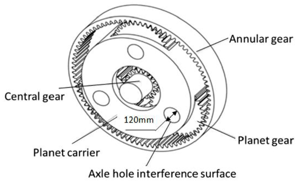
Planetary gear geometry model.
The parameters of the planetary gear are shown in Table 3.
Transmission parameters of the planetary gear system.

Because the three planetary wheels are symmetrically distributed periodically around the solar wheel, this model only takes axle hole of the planet carrier for analysis corresponding to a pair of planet gear and sun gear. The magnitude of the transmission torque is 193 kN m.
According to the working conditions of the planetary gear train, the revolute joints of planet carrier and rack, sun gear and rack are set as Body-Ground, the radial and axial displacements are set to 0, and their circumferential rotational degrees of freedom are released. Rotation of the planet gear shaft and planet gear is set as Body-Body. The contact between the planet gear axle and planet carrier is set as interference contact, and the parameters of friction coefficient and interference amount are set. The contact between each gear pair is set as non-friction contact. The input shaft material is 42CrMo. The planet carrier material is 35CrMo. The sun gear and planet gear material is 17CrNiMo6. The gear ring material is 30Cr2Ni2Mo. The default setting of material parameters is selected.
Hybrid meshing method is used for planetary gear train. By volume cutting, the pin-axis connection at the axis hole of the planet carrier is divided into several geometric models that can map structured meshes, and the hexahedral element type called solid45 is selected to mesh them. The contact pair of gear pairs is simulated by target units tagre170 and conta173, and the offset and friction coefficient are set. For the meshing between the planetary gear and solar gear, the structured hexahedral mesh is used in the gear part, and the mesh at the gear part is refined. The tetrahedral mesh is used in the other parts of the planet gear and sun gear. Study shows that when the axial grid is divided into 10 parts and the circumferential grid is divided into 50 parts, the calculation error of slip velocity is 1.6%, less than 5%, which meets the requirements of grid calculation accuracy.
Result analysis
In general, the relative slip with the slip amplitude in the range of 5–400 μm is called fretting slip. Figure 5 shows the relative slip value of interference fit surface. It can be seen that the slip amplitude of the interference surface is in the range of 0–100 μm, so there is fretting slip at the planet carrier shaft hole, which leads to fretting wear.

Relative slip distance of interference fit surface.
Characteristic parameters of fretting wear
The main characteristic parameters of fretting wear are the positive pressure on the contact surface at the shaft hole and the relative slip velocity between the contact surface and the target surface.
Figure 6 shows the stress distribution at the axis hole of the planet carrier. It can be seen from the figure that the stress concentration at the contact edge of the hole near the axis of the planet carrier is obvious. It may be caused because of the stress singularity existing there and bending moment.
Distribution of normal stress in the axle hole of the planet carrier.
Figure 7 shows the relative slip velocity of the interference fit surface of the planetary frame axle hole. It can be seen from the graph that the relative slip velocity distribution in the circumferential direction and the axial direction of the shaft hole is similar. The relative slip velocity at both ends is larger, and the relative slip velocity at the middle part is smaller. The circumferential direction is the main direction affecting the relative slip distance.

Relative slip velocity of interference fit surface in multiple directions: (a) circumferential direction, (b) axial direction, and (c) composition direction of circumferential direction and axial direction.
Validation of the feature parameter extraction method
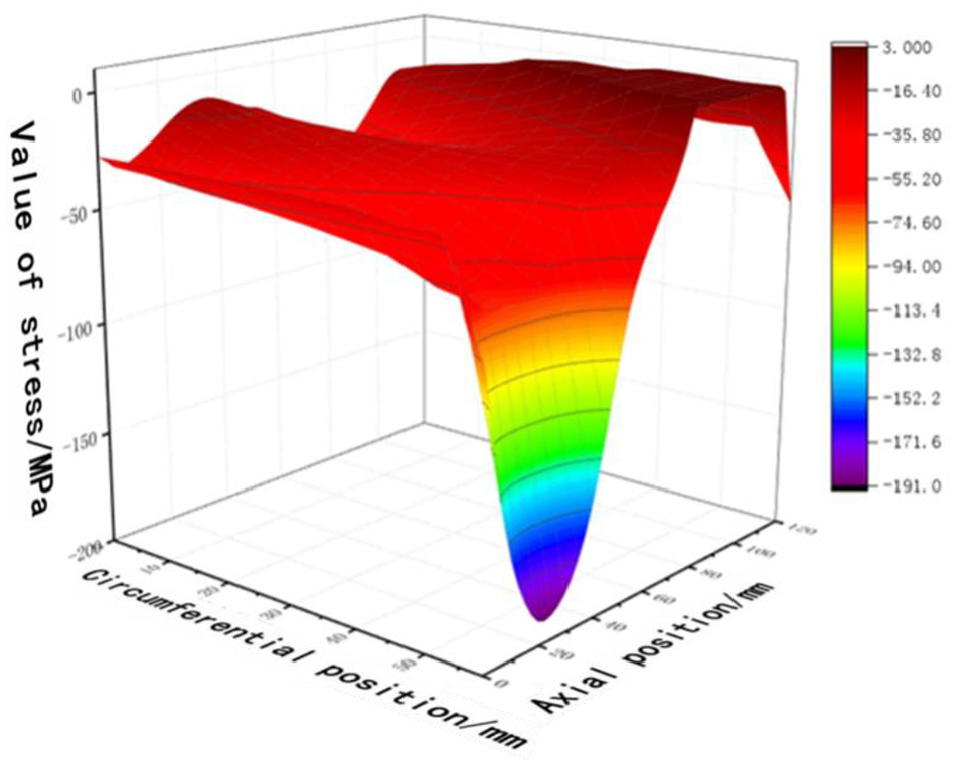
The interference fit surface at the axis hole of the planetary carrier is a cylindrical surface, which is expanded from the inner side of the cylindrical surface in the form of a plane. The circumferential direction of the cylindrical surface is defined as the x-axis, the axial direction of the cylindrical surface is defined as the y-axis, and the z-axis coordinate is the stress nephogram of the positive pressure on the surface of the planetary carrier’s axle hole caused by the contact of the planetary frame’s axle hole at a certain time, as shown in Figure 8.

Stress nephogram of the axle hole of the planetary frame.
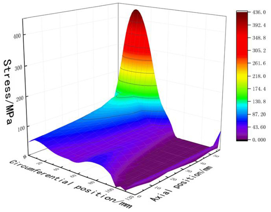
According to the variable amplitude extraction method proposed in section “Data extraction method of characteristic parameters,” the positive pressure at the axis hole is extracted, and the amplitude extraction method is verified. Assuming that the method is correct, the normal stress distribution should correspond to the values of each node in the stress nephogram at that time and show the same distribution law. Figure 9 shows the result of visualization operation of MATLAB after extracting data from the result file by the APDL program.
Display of data extracted by the APDL program by MATLAB.
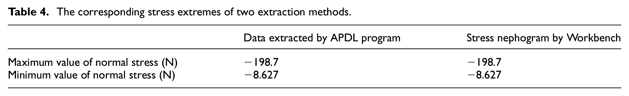
It can be seen that the stress extreme value and the related distribution law are consistent with the distribution law and data of normal stress nephogram by comparing Figures 7 and 8, and from Table 4, which verifies the correctness of the extraction procedure.
The corresponding stress extremes of two extraction methods.
Effect of interference on fretting wear depth
The main factors affecting fretting wear of contact surface are interference and friction coefficient. According to the method described in section “Data extraction method of characteristic parameters,” the values of normal stress and relative slip velocity under the same friction coefficient and different interference values are extracted, and the fretting wear depth is calculated by equation (1). The average value of fretting wear calculation results of each node at the axis hole of the planetary frame is taken to analyze the influence of interference on fretting wear depth.
Increasing the interference amount can reduce the slip value of the interference fit surface, but increasing the interference amount will also increase the contact pressure of the fit surface, which may change the contact state of the interference fit surface. Therefore, the influence of the interference amount on fretting wear is very complex. In actual production activities, the interference amount of the interference fit surface of planetary carrier shaft holes is usually 0.03 mm. In this article, the interference is selected in the range of 0.01–0.05 mm to study the relationship between fretting wear and interference. Figure 10 shows the variation of wear loss with interference amount when the friction coefficient is 0.2.

Variation of wear loss with interference amount.
From Figure 10, it can be seen that the average wear loss in both axial and circumferential directions increases with the increase in interference, while the wear loss in the axial direction plays a dominant role in the whole meshing process. With the change of the interference amount, the average wear loss of the axial direction shows a positive linear relationship with the increase in the interference amount, while the average wear loss of the circumferential direction does not show a linear trend, but increases with the increase in the interference amount.
Conclusion
A method of extracting finite element data suitable for the rotating body is proposed, which can accurately obtain the velocity, displacement, and stress of a point and an analysis step. The method is used to extract the positive pressure value at the hole, the stress extreme value, and the related distribution law, which coincide with the distribution law and data on the normal stress nephogram and verify the correctness of the extraction program.
When the friction coefficient is constant, the average wear in the axial and circumferential directions increases with the increase in interference, and the wear in the axial direction plays a dominant role in the whole meshing process. With the change of interference, the average wear of the axial direction shows a positive linear relationship with the increase in interference, while the average wear of the circumferential direction does not show a linear trend, but increases with the increase in interference.
Footnotes
Handling Editor: James Baldwin
Data availability
The data used to support the findings of this study are included within the article.
Declaration of conflicting interests
The author(s) declared no potential conflicts of interest with respect to the research, authorship, and/or publication of this article.
Funding
The author(s) disclosed receipt of the following financial support for the research, authorship, and/or publication of this article: The authors are grateful for the financial support from the National Key R & G project (No. 2016YFC0303703).