
Abstract
The dynamic response of a helical gear pair system is investigated. A new dynamic model for a helical gear pair system, considering three-dimensional motion due to bearing deformation, is proposed. The proposed model considers the helix angle, gear pair center distance, transverse pressure angle, and the contact ratio as time-dependent variables, which are considered as constants in other models. In fact, three-dimensional motion due to bearing deformation will lead to the changes in a series of dynamic responses. The system equations of motion were obtained by applying Lagrange’s equation and the dynamic responses are computed by the fourth-order Runge–Kutta method. The time-varying dynamic displacements, helix angle, gear pair center distance, transverse pressure angle, and the contact ratio are investigated with bearing deformation, different radial bear stiffness, different axial bear stiffness, and gear eccentricity. The results show that, due to the time-varying effect, this new helical gear pair model provides more accurate dynamic responses than those previous models which are considered as constant. In the future, this study can provide some useful information for the time-varying dynamic design of a helical gear pair system.
Keywords
Introduction
With the advancement of technology, the gear system is one of the most important components and commonly used in many industrial applications, such as automotive, wind turbines, aircraft, generator, and robotic arms. Generally, improvements in the rotational speed and efficiency of such machinery may cause problems such as noise and vibration. In recent years, gear systems are becoming more and more complex which need more accurate analysis. Therefore, a more realistic dynamic model of the helical gear pair for prediction of the noise and vibration response is necessary.
There are more studies that have been conducted in the gear pair system dynamics area. Umezawa et al. 1 proposed a simulator which solves a differential equation with 1 degree of freedom (DOF) in consideration of the behavior of the stiffness around tooth tip meshing and makes easier on the profile of a spur gear which decreases the vibration. Kahraman and Singh 2 discussed the nonlinear frequency response characteristics of a spur gear pair with backlash for both external and internal excitations. The digital simulation technique and the method of harmonic balance have been used to develop the steady-state solutions for the internal sinusoidal excitation. Frequency response solutions for the gear pair have been constructed using the method of harmonic balance. Kahraman and Singh 3 also developed a 3-DOF dynamic model which includes nonlinearities associated with radial clearances in the radial rolling element bearings and backlash between a spur gear pair. The gear meshing stiffness is assumed to be linear time invariant. Huang and Liu 4 modeled a spur gear tooth as a variable cross-section Timoshenko beam. A non-linear contact stiffness was used to deal with the dynamics of spur gears. Gao et al. 5 developed a finite element formulation to describe the nonlinear contact impact behavior of bevel gears. This approach can be used to analyze the complicated contact impact behavior of various products during high-speed rotation and can also be used to design low-vibration and low-noise geared rotor systems. Li and Kahraman 6 proposed a tribo-dynamics model which couples a mixed elastohydrodynamic lubrication model of a spur gear pair with a transverse–torsional dynamic model.
Helical gear pair systems considered the axial force problem and have been extensively studied. Kahraman 7 developed a linear dynamic model of a helical gear pair which has been performed to investigate the effect of the helix angle on the free and forced vibrational characteristics of the gear pair. Kubur et al. 8 proposed a dynamic model of a multi-shaft helical gear which could help the designers not only predict the dynamic behavior of the system but also come up with the most favorable configuration for the most desirable dynamic behavior. Zhang et al. 9 developed a general gear dynamic model with 12 DOFs and proposed a dynamic model of a multi-shaft geared rotor system. The dynamic behavior of a double-helical gear pair is investigated both experimentally and theoretically by Kang and Kahraman. 10
Advanced technology applications have a general requirement that the gear systems and designed to maximum load capacity be increased. The ability to accurately calculate the dynamic loads in gear systems becomes essential for advanced transmission design. A gear system with time-varying variables or time-varying gear mesh stiffness could improve the gear system accuracy. Ozguven and Houser 11 simulated time-varying mesh stiffness approximately using a constant mesh stiffness with transmission error excitation. Kim et al. 12 developed a new dynamic model which analyzed the dynamic response of a spur gear pair by considering the pressure angle and the contact ratio as time-dependent variables, as well as gear set translational motion due to bearing deformation. Ma et al. 13 proposed an improved mesh stiffness model in which the gear tooth is modeled as a nonuniform cantilever beam on the root circle and is more accurate compared with the traditional mesh stiffness model in which the gear tooth is modeled as a cantilever beam on the base circle. Saxena et al. 14 discussed the effect of time-varying friction coefficient on the total effective mesh stiffness for the spur gear pair and indicated that the gear mesh stiffness changed due to the change in the direction of time-varying friction on both sides of the pitch line. The effects of helix angle, mechanical errors, and coefficient of friction on the time-varying tooth-root stress of the helical gear pair have been investigated by Zhan and Fard. 15 Wang et al. 16 developed an improved time-varying mesh stiffness model of a helical gear pair, in which the total mesh stiffness contains the axial tooth bending stiffness, axial tooth torsional stiffness, and axial gear foundation stiffness. Huangfu et al. 17 developed a new method for calculating the time-varying mesh stiffness of helical gears. This model has four types of spatial crack, including addendum nonpenetrating crack, addendum penetrating crack, end-face nonpenetrating crack, and end-face penetrating crack. Yi et al. 18 considered the time-varying pressure angle and backlash simultaneously in a nonlinear dynamic model for a spur gear system. Feng et al. 19 discussed that the time-varying mesh stiffness of the helical gear pair is obtained by the slice method which divides the teeth into multiple spur gears along the tooth width. Marafona et al. 20 developed an algorithm capable of generating constant mesh stiffness gears which take into account the gear safety factors and gear mesh efficiency. A three-dimensional (3D) finite element model for calculating the time-varying meshing stiffness of a spur gear pair with complex foundations and cracks was established by Wang et al. 21 However, the dynamic characteristics of a helical gear pair system with 3D motion due to bearing deformation have not been studied.
In order to analyze the 3D motion effect, this article presents a new dynamic model for a helical gear pair system with 3D motion due to bearing deformation which includes the time-varying behaviors of the contact ratio, pressure angle, helix angle, and gear pair center distance.
Dynamic model of a helical gear system
The schematic of a helical gear pair system is shown in Figure 1. In this system, the pinion and gear are assumed to be rigid disk and gear pair centers supported by a pair of deformable rolling bearings that can be modeled as five spring stiffness in the x, y, z,

Parameter model of a helical gear pair.
Figure 2 describes a general helical gear dynamic model with 12 generalized coordinates as they are assumed to be 3D motion. Each disk has three translational coordinates and three rotational coordinates.

Generalized coordinates for the helical gear pair.
Generally, the gear pair center distance, transverse operating pressure angle, and helix angle were regarded as constant in all of the previous studies. Considering the gear pair center’s 3D motion, gear centers can move to

The transverse operating pressure angle is changed from

where

where

where the transmission error is ignored.

η is the axial relative position angle of the gear pair, which is between the line connecting the center of the gear pair and the positive x-axis and is defined as

According to the definition of the contact ratio for a helical gear pair, the total contact ratio

where
Figure 3 shows the nonlinear gear mesh stiffness which is described as a periodic function with mesh period Tm. There is three-tooth contact when time t is in the range of (n– 1)Tm to (mp+n– 3)Tm, where n is any positive integer, and the mesh stiffness is represented by the upper curve. There is two-tooth contact if t is in the range of (mp+n– 3)Tm to nTm, and the mesh stiffness is represented by the lower curve. The nonlinear gear mesh stiffness is accounted for by transverse tooth bending stiffness, transverse tooth shear stiffness, transverse tooth radial compressive stiffness, transverse gear foundation stiffness and Hertzian contact stiffness, axial tooth bending stiffness, axial tooth torsional stiffness, and axial gear foundation stiffness. The detail of nonlinear gear mesh stiffness is shown in Wang et al. 16

Nonlinear gear mesh stiffness model.
Derivation of the equations of motion
The differential equation of motion for a helical gear pair can be derived by the 12 generalized coordinates. The vector form is written as

When considering the helical gear set is a 3D motion, the kinetic energy T, potential energy U, and dissipation function F of the helical gear pair system can be expressed as follows

The radial displacement vectors can be denoted as

where
Due to the bearings’ deformations, potential energy can be expressed as

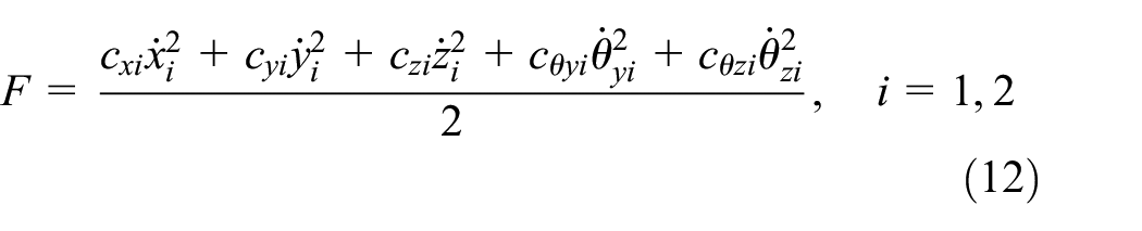
The dissipation function is given by
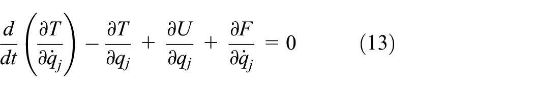
The differential equations of motion are obtained by applying Lagrange’s equation, which is given by
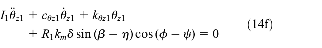
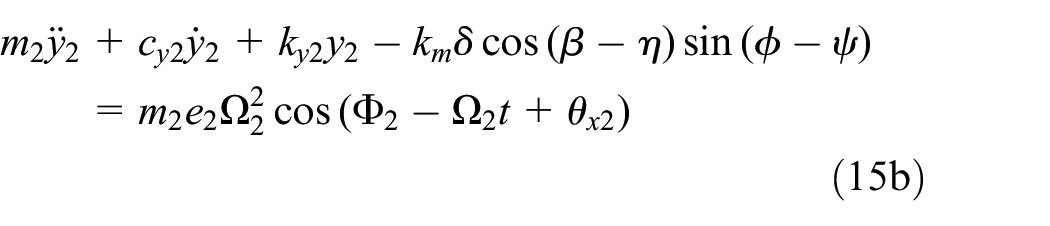
Substituting equations (9), (11), and (12) into equation (13) and considering the gear mesh effect, the equations of motion of a helical gear pair system can be obtained as


Validation and result discussion
In order to verify the accuracy of the proposed model, I chose a helical gear pair system of Kahraman 7 for verification. The helix gear pair system is shown in Figure 4, where the gear ratio is 1, the face width is 0.03 m, and the gear mesh coefficient is 2 × 10⁸ N/m. The other material parameters are shown in Table 1. It can be seen from Figure 5 that the natural frequencies obtained from the proposed model are similar to the results of Kahraman. 7 This means that the presented new model has good accuracy.

Dynamic model of a helical gear pair system. 7
Helical gear pair parameters of Kahraman 7 .


Natural frequencies for the (a) presented model and (b) Kahraman. 7
Case 1: time-varying effect on dynamic responses
Although many dynamic models for the helical gear system were presented, few studies have considered the time-varying effect and 3D motion due to bearing deformation in the dynamic model at the same time. The time-varying helix angle and 3D motion due to bearing deformation can lead to some different dynamic characteristics, which in the previous model are usually ignored. This section presents the results of time-varying numerical simulations for a helical gear pair system. The following data are used in the calculation for the helical gear pair system. In addition to the external torque, the pinion and gear adopt the same data. The torque applied to the pinion is 10 N m, the rotating speed is 3000 r/min, the bearing axial/radial stiffness is 1e6 N/m, and the bearing bending stiffness is 1e3 N/m. Table 2 lists the other parameter values of the system. The above parameters refer to Zhang et al. 9 and Kim et al. 12 All the responses in the following are computed by the fourth-order Runge–Kutta method. 22
Time-varying helical gear pair parameters.

In Figure 6, solid lines show the time histories (with bearing deformation) of the relative displacement of the gear mesh and the axial and lateral displacements of the pinion and gear with bearing deformation. According to the same parameters of the pinion and gear, the displacements of the pinion and gear will be equal. Figure 6 shows the dynamic displacements of the driving gear. The fluctuation magnitudes of the radial displacement are around 0.2043 mm, the x1 displacement is around 0.07502 mm, the y1 displacement is around 0.06845 mm, the z1 displacement is around 0.1925 mm, the θy1 displacement is around 0.6148 mrad, and the θz1 displacement is around 1.7295 mrad, and these are larger than the constant values (without bearing deformation). The θx1 displacement is not shown because torsional stiffness is not considered.

Time-varying (a) radial displacement, (b) x1 displacement, (c) y1 displacement, (d) z1 displacement, (e) θy1 displacement and (f) θz1 displacement of driving gear with and without bearing deformation.
As shown in Figure 7, solid lines show the time histories of the helix angle, transverse pressure angle, gear pair center distance, transverse contact ratio, overlap contact ratio, and the total contact ratio. As shown in this figure, the fluctuation magnitudes of the helix angle are around 20.049 degrees, the transverse pressure angle is around 20.425 degrees, the gear pair center distance is around 52.21 mm, the transverse contact ratio is around 1.5802, the overlap contact ratio is around 0.8593, the total contact ratio is around 2.4395, and the relative displacement of the gear mesh is around 0.057855 mm.

Time-varying (a) helix angle, (b) transverse pressure angle, (c) gear pair center distance, (d) transverse contact ratio, (e) overlap contact ratio, (f) total contact ratio and (g) relative displacement of helical gear pair with and without bearing deformation.
We can see the time-varying effect from these values. To sum up, the time-varying variables have a notable effect on dynamic responses of the helical gear pair and provided more realistic numerical simulation values.
Case 2: effect of axial bearing stiffness
In order to analyze the axial bearing stiffness, three cases of axial bearing stiffness are discussed in this section. Case 1 is for axial bearing stiffness kx = 1e6 N/m, Case 2 is for kx = 2e6 N/m, and Case 3 is for kx = 5e6 N/m. Figure 8 presents the time histories for the axial displacement of the pinion and gear, the helix angle, the axial relative angle, the overlap contact ratio, and the total contact ratio of the helical gear pair. If the axial bearing stiffness increased, the axial displacement of the pinion and gear, and the overlap contact ratio decreased but the axial relative angle is enhanced. According to the total contact ratio equal to the transverse contact ratio plus overlap contact ratio, the total contact ratio is decreased with the overlap contact ratio. The axial bearing stiffness has a large effect on the axial displacement, axial relative angle, overlap contact ratio, and the total contact ratio, but it has only a small effect on helix angle.

Time-varying (a) axial displacement of pinion, (b) axial displacement of gear, (c) helix angle, (d) axial relative angle, (e) overlap contact ratio and (f) total contact ratio of helical gear pair under different axial bearing stiffness.
Case 3: effect of radial bearing stiffness
The effects of the radial bearing stiffness on the radial displacement, transverse pressure angle, gear pair center distance, helix angle, transverse contact ratio, overlap contact ratio, and the total contact ratio of the helical gear pair system have been analyzed under different radial bearing stiffness. Case 1 is for radial bearing stiffness ky = kz = 1e6 N/m, Case 2 is for ky = kz = 2e6 N/m, and Case 3 is for ky = kz = 5e6 N/m. It can be seen from Figure 9(a)–(e) that the time-varying results of the radial displacement, transverse pressure angle, gear pair center distance, and the transverse contact ratio reduced with the radial bearing stiffness being enhanced. These values have the same trend in the spur gear pair system. 12 The other dynamic characteristics of the helical gear pair, such as helix angle, overlap contact ratio, and total contact ratio, are shown in Figure 9(f)–(h). When the radial bearing stiffness increased, the helix angle and total contact ratio decreased, but the overlap contact ratio just has a little difference. The radial bearing stiffness has a great effect on the radial displacement, transverse pressure angle, gear pair center distance, transverse contact ratio, helix angle, and total contact ratio of the helical gear pair system.
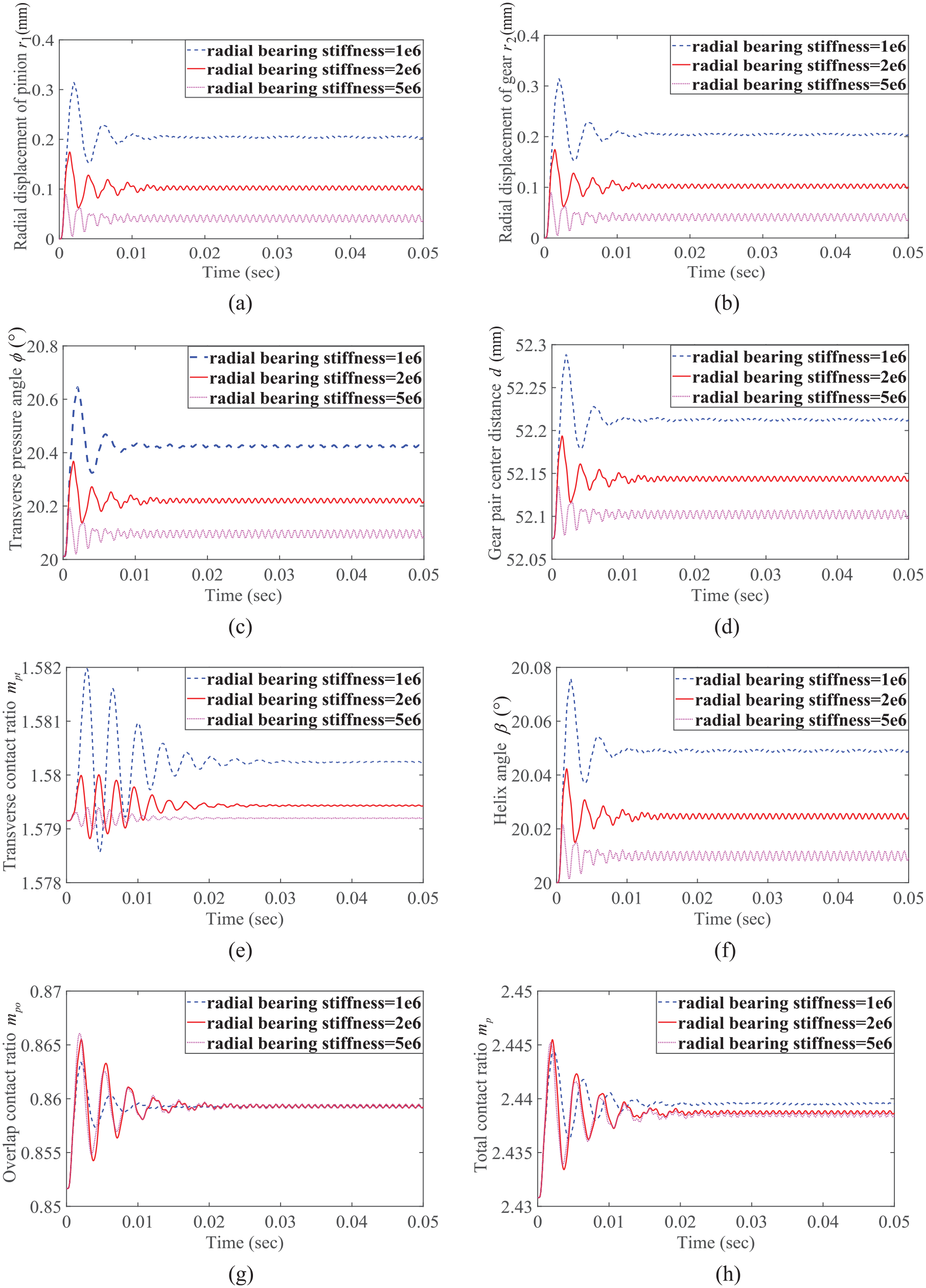
Time-varying (a) radial displacement of pinion, (b) radial displacement of gear, (c) transverse pressure angle, (d) gear pair center distance, (e) transverse contact ratio, (f) helix angle, (g) overlap contact ratio and (h) total contact ratio of helical gear pair under different radial bearing stiffness.
As shown in Figures 8 and 9, it is interesting that the results of the dynamic characteristics of the helical gear pair with time-varying variables are close to original values when the axial bearing stiffness or the radial bearing stiffness is sufficiently large. This implies that the time-varying variables have a significant influence on the general stiffness, but they have only a little effect on the large stiffness.
Case 4: effect of disk eccentricity
In this section, we will discuss the dynamic characteristics of the helical gear pair under three different gear eccentricities. Case 1 is for e1 = e2 = 0·R1, Case 2 is for e1 = e2 = 0.01·R1, and Case 3 is for e1 = e2 = 0.03·R1. It can be seen from Figure 10 that gear eccentricity has some influence on the radial displacement of the pinion and gear, and the transverse relative angle, but has almost no effect on the transverse pressure angle. The figure also shows that gear eccentricity has a great influence on the transverse contact ratio, and the total contact ratio is enhanced as the overlap contact ratio increases. With the gear eccentricity being raised, the amplitude magnitudes of the periodic fluctuation for the above dynamic characteristics are enhanced, especially in the transverse contact ratio and total contact ratio.

Time-varying (a) radial displacement of pinion, (b) radial displacement of gear, (c) transverse pressure angle, (d) transverse relative angle, (e) transverse contact ratio and (f) total contact ratio of helical gear pair under different gear eccentricity.
Conclusion
A new dynamic model for a helical gear pair system, considering 3D motion due to time-varying bearing deformation, is proposed. The model of the system was built with two nodes and 12 DOFs. The Lagrange method is used to derive the equations of motion of the system and solved by the numerical integration method. Based on this model, the dynamic characteristics of the radial displacement, axial displacement, helix angle, gear pair center distance, transverse pressure angle, and the contact ratio are analyzed. The results of this study can be summarized as follows:
This research proposed a new dynamic model of a helical gear pair system that considers the time-varying behaviors of the helix angle, gear pair center distance, transverse pressure angle, and the contact ratio.
The proposed new model provides more accurate dynamic responses than those previous models which are considered as constant.
With the axial bearing stiffness being increased, the axial displacement and the total contact ratio decreased, but the axial relative angle is enhanced. The axial bearing stiffness has only a small effect on the helix angle.
When the radial bearing stiffness is increased, the helix angle, axial displacement, transverse pressure angle, gear pair center distance, transverse contact ratio, and the total contact ratio are reduced, but the overlap contact ratio just has a little effect.
The time-varying variables have a significant influence on the general stiffness for a helical gear pair system but have only a little effect on the large stiffness.
With the gear eccentricity being raised, the radial displacement and the transverse relative angle are enhanced; especially, both the transverse contact ratio and the total contact ratio have increased greatly, but the transverse pressure angle has almost no influence.
Footnotes
Handling Editor: James Baldwin
Declaration of conflicting interests
The author(s) declared no potential conflicts of interest with respect to the research, authorship, and/or publication of this article.
Funding
The author(s) received no financial support for the research, authorship, and/or publication of this article.