
Abstract
To reduce the vibration of the propeller blades, a novel unmanned underwater vehicle–integrated piezoelectric additive manufacturing technology is proposed in this article. The operating principle and design procedure of the proposed unmanned underwater vehicle are illustrated. Utilizing piezoelectric dynamic theory and Lagrange’s equation, the coupled vibration equations of piezoelectric-propeller blades system under complex excitation are established. Applying MATLAB simulation method, the dynamic responses of the coupled blades under external and piezoelectric excitation are investigated. With finite-element method software, the correctness of the theoretical analysis is verified. Results show that the maximum amplitudes of the propeller blades are distributed at the end of the blades, thus placing the piezoelectric layers at the terminal blades can minimize the vibration of the propeller blades. Meanwhile, the vibration amplitudes of propeller blades can be reduced by more than 70% by applying piezoelectric coating. These results can be used to reduce the vibration and improve the dynamic performance during the unmanned underwater vehicle operating.
Introduction
With the advance of science and technology, unmanned underwater vehicle (UUV) has been widely used in areas such as underwater detection, oceanographic surveys, and undersea rescues.1–3 However, the vibrations of the propeller that is excited by water wave affect the dynamic performance of the UUV seriously.
For the vibrations of the propeller, numerous achievements have been made by researchers from all over the world. Utilizing Bragg gratings sensing system, Javdani et al. 4 investigated the free vibration of ship propeller. It shows that the natural frequency ratio of propeller in water and air increases linearly with the increase of natural frequency. In addition, the sea depths, in varying degrees, affect the natural frequencies. Using URANS computations, Martio et al. 5 solved the virtual mass and damping coefficients of an open and ducted propeller. The magnitude order of the coefficients is consistent with the computational fluid dynamics (CFD) method. Besides, Prabhu et al. 6 studied the changing of hydrodynamic load of propeller blades under the action of steady flow and unsteady flow, simulated the influence of blade structure dynamics on hydrodynamic load, and analyzed the influence of the mixed action of structure dynamics and hydrodynamic load on propeller blade under different working conditions. For the free vibration of the rotating pre-twisted functionally graded structures, Liu et al. 7 built a new structural dynamic model of rotating pre-twisted functionally graded sandwich blades. The sandwich blade is made up of two functionally graded skins and a homogeneous material core. In their model, the thick shell theory is applied to derive the basic equations of motion of the sandwich blade by considering the effects of centrifugal and Coriolis forces. And the ANSYS software is used to verify the theoretical analysis results. The results indicated that the phenomena of frequency locus veering and mode shape exchanging occur in the static and dynamic states. Meanwhile, Niu et al. 8 investigated the free vibrations of the rotating pre-twisted functionally graded composite cylindrical panels reinforced with the graphene platelets by considering the cantilever boundary conditions. Utilizing the Halpin-Tsai model and the rule of the mixture, the effective Young’s modulus is calculated and the effective Poisson’s ratio and mass density are derived. Furthermore, the natural frequencies of the rotating pre-twisted functionally graded composite cylindrical panel are calculated with Chebyshev-Ritz method. The numerical results solved by the new method are in good agreement with the ANSYS simulation results.
What’s more, to investigate the coupled vibrations of propeller, Hua and colleagues’9–11 research team had achieved significant advances in longitudinal vibration of propeller shafts under turbulence excitation, propeller blade vibration induced by inflow, structural vibration and acoustic radiation of propeller shafts and underwater hull coupling system. With finite-element method (FEM), Liu et al.12,13 studied the vibrations of propeller–shaft–hull coupling system. The results show that the vibration modes of the propeller vary in air and water, and the dynamic characteristics of the thrust bearing for the coupling system would affect the power flow into each bearing, which results in the corresponding changes in the coupling vibration of the system. Moreover, the noise of a propeller constitutes an important part of ship underwater noise, which affects the stealth performance of ships. To calculate the noise induced by vibration of propeller blades, the numerical simulation of propeller open-water performance was conducted by means of CFD, and the vibration response analysis of the propeller was performed with FEM. 14
For the nonlinear dynamic characteristics of the blades and plates, significant advances have been obtained. Yao et al. 15 studied the nonlinear dynamic responses of the rotating blade with varying rotating speed under high-temperature supersonic gas flow. In the dynamic model of the blades, the varying rotating speed and centrifugal force are applied. Through numerical simulations, the nonlinear dynamic responses of the rotating blade are investigated. Simulation results indicate that the periodic motions and chaotic motions occur during the nonlinear vibrations of the rotating blade. Wang and Zhang 16 studied the stability of a nonlinear rotating blade with torsional vibrations. It integrates linear model and geometric nonlinear model features. For its geometric nonlinear model, the multiple time scale method is used to investigate the steady-state solutions, and their stability and bifurcations for the periodically time-varying rotating blade. Besides, the backbone curves of steady-state motions are achieved, and the parameter map for stability and bifurcation is developed as well. In addition, Yao et al.17,18 analyzed the nonlinear oscillations and resonant responses of compressor blade with Hamilton’s principle and Galerkin’s approach. Using Galerkin approach and asymptotic perturbation method, the nonlinear dynamics of the high-speed rotating plate are developed. Using spreading residue harmonic balance method, Guo and Zhang 19 studied the vibration frequencies of tapered beams. With this new solution method, no small parameter is assumed and all former residual errors are introduced in the present approximation to improve the accuracy. What’s more, the proposed method is quickly convergent and only the first-order analytical approximation leads to high accuracy of the solutions. For the non-deterministic factors of an aeroengine blisk, Bin et al. 20 proposed probabilistic and non-probabilistic hybrid reliability analysis based on dynamic sub-structural extremum response surface decoupling method to solve the problems. The computational efficiency of the new method is more reasonable for designing a mistuned blisk.
To reduce the vibrations of propeller blades, numerous achievements have been made by researchers. At present, the commonly used vibration suppression methods of propeller mainly include three forms: improving the blade structure, using composite materials or composite coating on the blade surface, and increasing external damping or other vibration reduction devices.21,22 To some extent, the above methods suppress the vibrations of propeller blades, but those also increase the manufacturing process, cost, or external volume of the propeller.
Thus, it is of great practical significance to propose a new vibration suppression method to solve the complex vibration problems of the propeller blades without changing the propeller’s structure and increasing the external mass and volume.
Therefore, the authors proposed a novel UUV with piezoelectric additive manufacturing (PAM) technology, and it can implement piezoelectric vibration reduction functionality of propeller blade. As piezoelectric material has many excellent performances, such as fast response, small size, and no electromagnetic interference, 23 hence, the vibration reduction effect of propeller blades can be greatly improved. For the proposed UUV, its propeller blades are fabricated by additive manufacturing, and a thin layer piezoelectric polyvinylidene fluoride (PVDF) is cover on the surface of the vibrational blades. As PVDF material is soft and deformable, it is suitable to be used for three-dimensional (3D) print. Hence, through PAM technology, the piezoelectric material constitutes a part of the propeller, and it will not affect the normal operation of the propeller during vibration attenuation.
The structure of the proposed UUV is presented in Figure 1; it consists of sonar (1), bow (2), water container (3), visual detection system (4), buoyancy cabin (5), pushing device (6), body structure (7), body structure (8), control cabinet (9), lithium battery (10), stern (11), and propeller (12). While in the propeller (12), a thin layer of piezoelectric material (12-2) is covered on the surface of blades (12-1).
Structure of the proposed UUV.
The vibration responses of propeller blades significantly influenced the overall performance of the UUV, which can result in the UUV with a bad stability. To reduce the vibrations of propeller blades, the authors proposed a novel vibration reduction method utilizing PAM technology. With this new method, a thin layer piezoelectric material PVDF is cover on the surface of the propeller blades. Under active excitation of piezoelectric signal, the vibration energy of propeller blades can be absorbed by PVDF material. In this article, the operating principle of the proposed UUV is presented. And the vibration equations of the piezoelectric-blades system are established. Meanwhile, the dynamic responses of the propeller under hybrid excitation are investigated. What’s more, the vibration attenuation of propeller blades with piezoelectric coating is studied as well. The theoretical studies lay a foundation for the application of piezoelectric materials in vibration reduction of propeller.
Operating principle of the UUV
The operating principle of the proposed UUV is presented as follows:
Initially, the buoyancy of the UUV is larger than its gravity. Therefore, the UUV floats on the water surface, the pushing device is in its elongated stage, while the magnetic valve that is connected to the water container is in a closed condition.
When the pushing device receives control signals from the control cabinet, it then shrinks, whereas the magnetic valve is connected under the command of the control signal. Meanwhile, the water is poured into the water container, thus the gravity of the UUV is larger than its buoyancy. Hence, the UUV dives into the underwater. When it reaches to the predetermined depth, the pushing device stretches under the command of the control signal, and then pushes the water container draining away part of the water to keep the UUV balance. Meanwhile, the controller commands the magnetic valve and the pushing device in a stage of outage, whereas the pushing device keeps elongation. At the same time, four thruster motors are commanded to rotate with the same speed, thus the UUV moves forward. When the rotation speeds of the two motors on one side are larger than that of another side, the UUV changes directions based on difference velocity principle.
When the UUV finishes its underwater task, all the thruster motors are powered off, while the pushing device and magnetic valve are powered on. And the pushing device returns to its initial stage, thus the water container drains away water. As a result, the buoyancy of the UUV is larger than its gravity, and then the UUV resurfaces.
Due to the PAM technology, the thin piezoelectric layer can reduce the vibration of blades without changing the appearance and inherent property of the propeller. The manufacturing process of piezoelectric-blades complex structure is shown in Figure 2. When printing the piezoelectric layer, the powdered material is put in the 3D printer at first, and the propeller blades are fixed on platform of the printer. And then a thin piezoelectric layer can be printed on the blades surface with 3D printer. After that, the piezoelectric layer needs to be polarized by special device. Finally, through wedding electrode and shunt circuit, the piezoelectric-blades complex structure can be obtained.

PAM principle of piezoelectric-blades complex structure.
The total length of the proposed UUV is 2738.62 mm, while its body diameter is 300 mm. In order to reduce the resistance when the UUV travels underwater, the bow adopts water drop curve structure, while the stern adopts a conical structure. The calculation formula of the bow can be expressed as
where D is the body diameter of the UUV, Xd is the horizontal axis of the bow, Ld is the total length of the bow, and nd is the shape parameter.
The maximum diving depth of the designed UUV is 300 m, and the maximum water pressure of which is 3 MPa. The body part is made of aluminum alloy; and its wall thickness is 10 mm. According to maximum shear stress theory and distortion energy theory, the maximum pressure of UUV shell can be calculated as follows
where σcir and σrad are circumferential stress and radial stress; Dmdl is the middle diameter of the shell; δthk is the wall thickness of shell.
It can be known from equation (2) that the maximum pressure of the shell is much larger than 3 MPa. Hence, the UUV can operate safely underwater.
The designed speed of the UUV is 5 kn, and the total thrust of the vehicle is

where ρ is the density of water, v is the UUV speed, A is the cross-sectional area of the UUV, and CD is the tension coefficient.
Hence, the power of propulsion motor can be expressed by

After calculation, the power of each motor is approximately 107.8 W, and a rated power of 110 W is selected.
Coupled vibration of the propeller blades
The structure and dynamic model of propeller blades are presented in Figure 3. Here, the blades are simplified as rectangular beam structure. Parameters lb and lp represent the length of blades and piezoelectric layers, while wb and wp, hb and hp represent their width and thickness. The piezoelectric layers locate at xp position of the blades. In Figure 3(b), M and Fs are bending moment and shear force of the propeller blades, respectively.
Structure and dynamic model of propeller blades: (a) blade–piezoelectric coupling structure and (b) dynamic model.
The equivalent circuit of the piezoelectric system is shown in Figure 4. Here, R is the resistance of the circuit, while C represents the capacitance of the piezoelectric layer. From Kirchhoff’s law and current–charge relationship, the balance equation can be expressed as

where Up–p is peak–peak value of voltage, and ω0 is the exciting frequency.
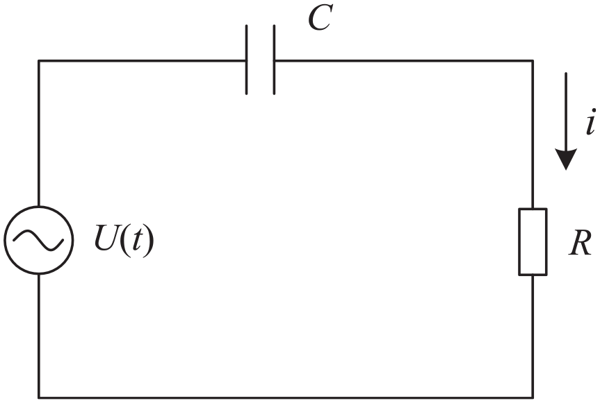
The equivalent circuit of a piezoelectric system.
Under zero initial condition, the voltage response of the piezoelectric layer is

The vibration displacement of the piezoelectric layer can be expressed by

In equation (7), qi(t) is the generalized displacement coordinate; φi(x) is the modal function. Since the ratio of section size to length of propeller blades is less than 5, the blades that contained piezoelectric layer can be simplified into Timoshenko model, and the bending vibration modal function and frequency equation of the system can be expressed as

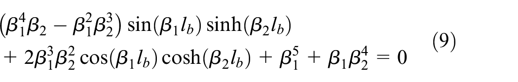
where β1 and β2 are the frequency coefficient, ρ and E are the density and elasticity modulus of the blades,
The stress of a piezoelectric layer is expressed as 24

where
Thus, the strain energy of a propeller blade and piezoelectric layer can be written as
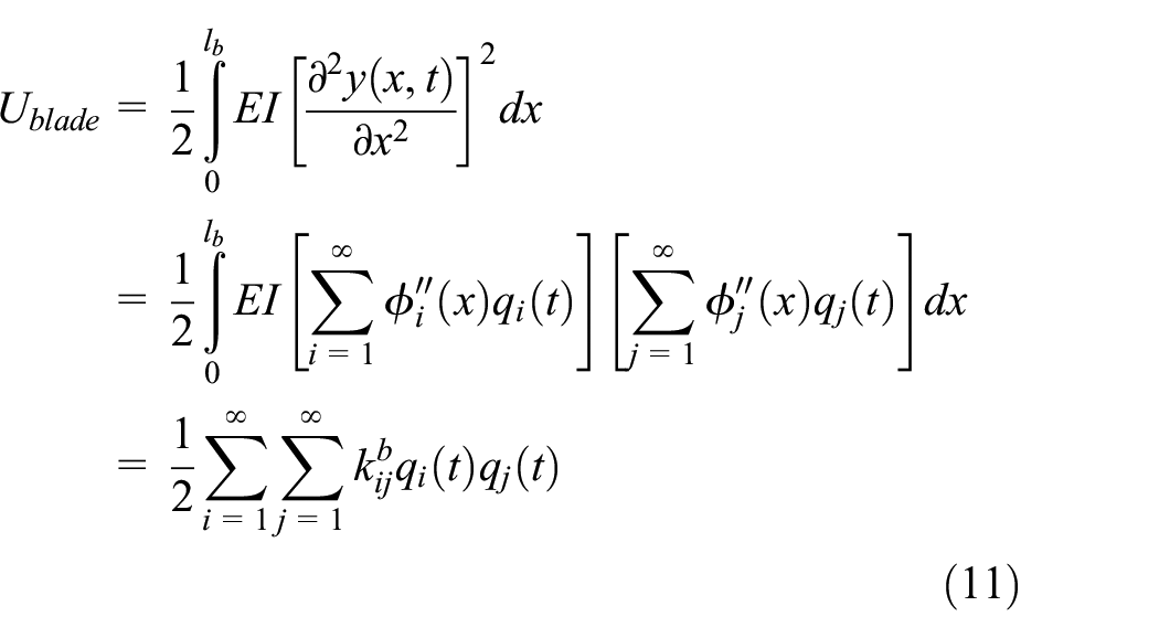

where
The total strain energy of piezoelectric-blade composite structure is

The total kinetic energy of the system can be written as

where mij is the modal mass,
Similarly, the dissipative function can be expressed by

where cij is the generalized damping,
According to Lagrange’s equation, the dynamic equation of piezoelectric-blade composite structure can be written as
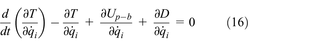
Substituting equations (13)–(15) into equation (16), and then simplify and rearrange the dynamic equation yields

where
Supposing that the operating point of the external excitation of the blade is at xe, thus the generalized force of the external excitation can be expressed as

where F0 is the amplitude of external excitation force.
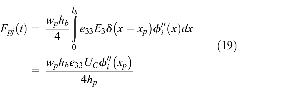
If the operating point of the piezoelectric layer is xp, the generalized force of the piezoelectric excitation can be written as
According to the Duhamel’s integral, letting the initial values of generalized coordinate are 0, thus the response of propeller blade under external excitation is
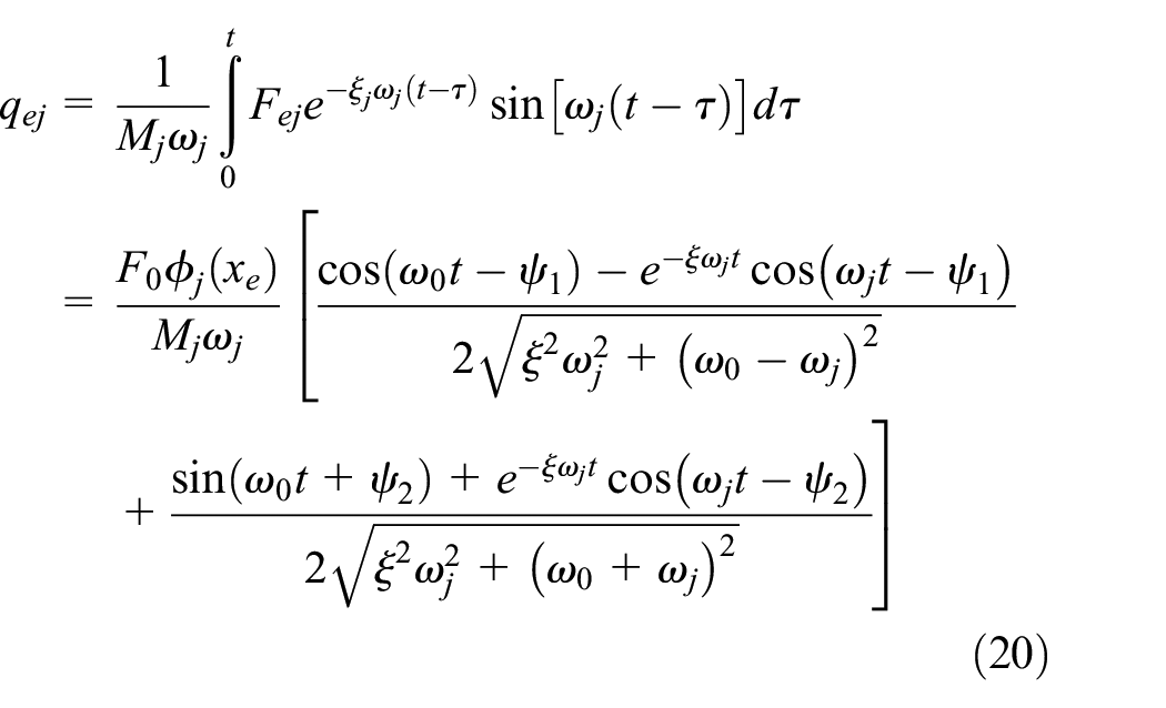
where
It is assumed that the propeller blades are applied to external excitation and piezoelectric excitation at the same time. The operating points are xp and xe, respectively. When the phase difference between the two excitations is π, the piezoelectric layer with an active excitation can serve as an active damping, thus the total excitation of the propeller blade is
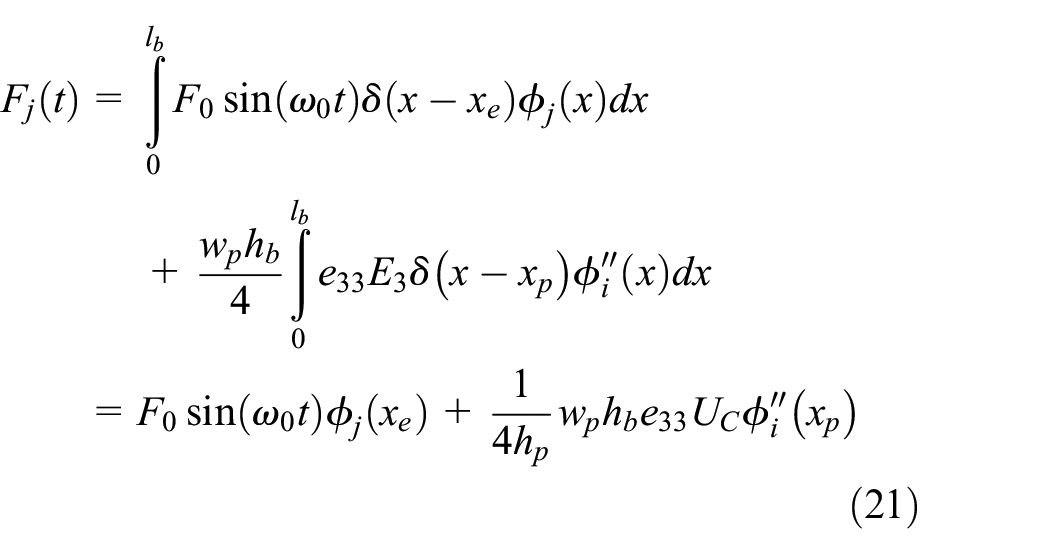
According to Duhamel’s integral, the time-domain response of the propeller blade under coupled excitation can be expressed as

Results and discussion
Modal analysis
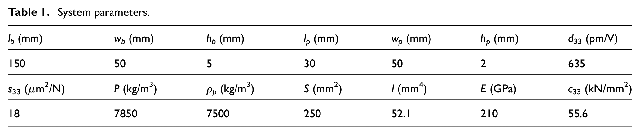
Table 1 presents the system parameters of the propeller blades structure. Substituting the parameters into equations (5) and (6), the natural frequencies and vibration modes of the blades system can be obtained as shown in Table 2 and Figure 5. From Table 2 and Figure 5, it can be observed that,
Due to the small size of the selected blades model, the corresponding natural frequency values are quite large. The first-order natural frequency is 11713 rad/s, and the frequency difference increases with the increase of the frequency order.
In each mode, the relative displacement of the terminal blade is much larger than that at other positions, which is determined by the properties of the Timoshenko model, and it is much different from Euler–Bernoulli model.
In the first two modes of the system, no complete period waveform appears, while the number of complete period waveform increases with the increase of frequency order.
System parameters.
System natural frequencies (rad/s).


Vibration modes of propeller blades: (a) first order, (b) second order, (c) third order, (d) fourth order, (e) fifth order, and (f) sixth order.
Therefore, the displacement of the terminal blades should be paid much attention. Meanwhile, in order to reduce blade vibrations as much as possible, the piezoelectric layers should be placed near the termination of the blades.
Time response analysis
As can be seen from the vibration modes indicated in Figure 5, the maximum vibration displacement of blades occurs at the end of blades. Therefore, when investigating the time-domain characteristics of propeller blades, the piezoelectric layers are selected to place at the end of the blades. Setting the amplitude of external excitation force F0 as 150 N and the peak-to-peak value of piezoelectric layer driving voltage Up–p as 50 V, the influence of piezoelectric excitation on forced response of the system with the change of excitation frequency is studied as shown in Figure 6. Furthermore, the influence of piezoelectric parameters on vibration reduction of blade system is investigated as well (see Figure 7). In Figure 7, excitation voltage Up–p, piezoelectric strain constant d33, piezoelectric layers thickness hp and width wp are selected to investigate the parameter influence. Meanwhile, “Ext. excitation” represents the responses excited by external excitation and nothing to do with piezoelectric excitation. Figures 6 and 7 show that,
With the increase of excitation frequency ω0, the amplitude of bending vibration at the end of the propeller blade first increases and then decreases, and it is larger when ω0 is close to the first-order natural frequency.
Under the effect of piezoelectric coupling excitation, the amplitudes of terminal blades decrease significantly, with an average reduction of 73.5%. It can be seen that piezoelectric active excitation plays an important role in reducing vibration of the blades.
With the increase of excitation voltage Up–p, the response displacements of propeller blades under coupled excitation decrease, and the effect of piezoelectric vibration reduction is enhanced. The reason is that when Up–p increases, the piezoelectric inverse vibration suppression forces increase.
The influence of piezoelectric strain constant d33 on blade response is similar to that of Up–p. The complex response displacement decreases with the increase of d33, and the piezoelectric vibration suppression effect is enhanced.
The thickness of piezoelectric layers hp has a great influence on the vibration suppression of the blades, and the response displacement changes significantly with hp changes. The effect of piezoelectric vibration suppression is inversely proportional to the increase of hp. This is because, the electric field intensity of the piezoelectric system is inversely proportional to hp. The smaller the hp, the greater the electric field intensity and the greater the output force of the piezoelectric layers.
The influence of piezoelectric layer width wp on the response displacement is smaller than that of hp, and the piezoelectric vibration suppression effect increases with the increase of wp.
Therefore, the vibration reduction of propeller blades can be achieved by applying electric excitation to piezoelectric layers. As the selected parameters change, the piezoelectric vibration suppression effect changes accordingly, among which Up–p has the largest influence on the piezoelectric vibration suppression effect.

Dynamic responses under different excitation frequencies: (a) ω0 = 100 rad/s, (b) ω0 = 1000 rad/s, (c) ω0 = 10,000 rad/s, and (d) ω0 = 20,000 rad/s.

Effect of parameters on dynamic response: (a) Up–p changes, (b) d33 changes, (c) hp changes, and (d) wp changes.
FEM simulation analysis
In order to verify the correctness of theoretical analysis, the modal characteristics and forced responses of piezoelectric-blade coupling system are simulated by FEM software ANSYS. Figure 8 shows the modal cloud diagram of the blade system with the first two-order frequencies. Table 3 shows the comparison of the simulated natural frequencies and the theoretical calculated frequencies. At the same time, the first-order resonance response of the blade system under the external excitation and the piezoelectric coupling excitation is analyzed, as shown in Figure 9. From Figures 8 and 9 and Table 3, it is known that,
In Figure 8, the first two-order modes of the blade system are basically the same as the modes obtained by theoretical calculation in Figure 5. All the blades are bending vibration and the maximum vibration displacement of the blades occurs at the end of the blades.
The first two-order simulation natural frequencies of the propeller blades are close to the theoretical natural frequencies, and the maximum error between them is 7.19%, which verifies the correctness of the theoretical calculation.
Through the FEM simulation, the resonance amplitudes of the blade system are greatly reduced under the piezoelectric excitation. Compared with the external excitation, the amplitude of the piezoelectric excitation is reduced by 70.5%, which is similar to the 73.5% that is obtained by theoretical calculation. This further verifies the effectiveness of the piezoelectric intelligent material for vibration suppression of propeller blades.

Modal cloud diagram of the blade system: (a) first-order mode and (b) second-order mode.
Comparison of simulation and theoretical frequencies.


First-order resonance response of propeller blades.
Therefore, by contrast theoretical analysis and simulation study, the correctness of the theoretical model is validated in this article. Meanwhile, the proposed piezoelectric-based UUV can realize the function of shunt circuit passive vibration suppression as well as active vibration suppression. These studies lay a theoretical foundation for the application and popularization of piezoelectric smart material used in UUV.
Furthermore, the system parameters (include excitation voltage Up–p, piezoelectric strain constant d33, piezoelectric layers thickness hp and width wp) are selected to investigate the effect of parameters on resonance response by ANSYS software as well. Figures 10–13 show the simulation results of resonance response with different parameters. From figures, it is known that,
The changes of the selected parameters influence the maximum amplitude of resonance response obviously. The maximum amplitudes of the coupled blades are inversely proportional to the increase of Up–p, d33, and wp, whereas those are proportional to the increase of hp. The reason is that the reverse suppression forces become larger with the increase of Up–p, d33, and wp. However, the reverse suppression forces become smaller with the increase of hp.
The variation of resonance amplitudes with parameters by FEM analysis is consistent with the time responses of coupled blades by numerical simulation. The difference is that the FEM analysis focuses on resonant response under the first-order resonant frequency, while the numerical simulation in section “Time response analysis” places emphasis on forced response under a certain frequency.
The changing rates of resonance amplitudes with Up–p, d33 and wp are larger than that with hp. Hence, the vibration amplitudes are more sensitivity to the changes of Up–p, d33, and wp. In order to obtain a more stable system, more attentions for the changes of Up–p, d33, and wp should be paid in the design of the piezoelectric vibration suppression system.
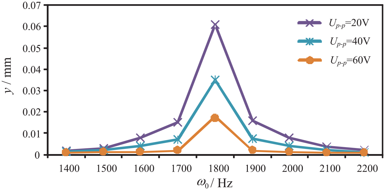
Effect of Up–p on resonance response.

Effect of d33 on resonance response.

Effect of hp on resonance response.

Effect of wp on resonance response.
In a word, a relative high excitation voltage Up–p, a large piezoelectric strain constant d33, a large piezoelectric layer width wp and a small piezoelectric layer thickness hp are necessary to obtain a better vibration suppression effect with piezoelectric material.
Conclusion
In this article, a novel piezoelectric-based UUV is proposed and its design process is presented. Using piezoelectric dynamic theory and Lagrange’s equation, the coupled vibration equations of the propeller blades under complex excitation are established. Utilizing these equations, the dynamic responses of blades under external excitation and piezoelectric excitation are solved as well. With FEM software, the correctness of the theory is verified. Results show that,
The maximum amplitudes of the propeller blades are distributed at the end of the blades, thus placing the piezoelectric layers at the terminal blades can minimize the vibration of the propeller blades.
The vibration amplitudes of propeller blades can be reduced by more than 70% using piezoelectric coating.
The simulation mode with FEM of propeller blades is similar to its theoretical mode, and the maximum error of the first two natural frequencies is 7.19%.
These results can be used to optimize the structure of the proposed UUV and reduce the vibration during the UUV operating.
Footnotes
Handling Editor: James Baldwin
Declaration of conflicting interests
The author(s) declared no potential conflicts of interest with respect to the research, authorship, and/or publication of this article.
Funding
The author(s) disclosed receipt of the following financial support for the research, authorship, and/or publication of this article: This research was funded by the National Key Research and Development Program of China (grant no. 2018YFC0309100), the National Natural Science Foundation of China (grant nos. 51905228 and 51705217), the Research Project of State Key Laboratory of Mechanical System and Vibration (grant no. MSV201808), the Natural Science Foundation of Jiangsu Higher Education Institutions (grant no. 18KJB460008), and the Science and Technology Innovation Project of Jiangsu University of Science and Technology for Youth (grant no. 1022921801).