
Abstract
Springback is always a technical problem in sheet metal forming. In this article, the rapid springback compensation control of two-dimensional hull plate is realized by theoretical calculation and numerical simulation. For the cylindrical shell, according to the bending forming theory of medium and thick plates, the total elastic-plastic bending moment is established, and the curvature change before and after springback is deduced. The curvature correction coefficient is determined by the precise numerical simulation technology. At the same time, the validity of the method is verified by cold bending experiment. For the shell with variable curvature, it is divided into several cylindrical surfaces according to the curvature gradient of its geometric section line. The compensation curvature array is obtained by the correction compensation algorithm of springback curvature of cylindrical plate, and the algorithm is verified by numerical simulation. The results show that the method is very close to the expected results. Thus, the efficiency and precision of forming will be improved, and the foundation of digitization of sheet metal forming is established.
Keywords
Introduction
The formation of hull shells, especially of large curved shells, has always been a most difficult problem in the field of plastic hull processing. The simple and effective shaping of ship plates with different thicknesses and curvatures to meet design requirements has always been the development direction of hull plate-forming technology. For a long time, two-dimensional parts, such as cylindrical and conical parts, have been formed by rolling or bending shown in Figure 1.1,2 When the bending resistance of the roller is relatively large, the roller will be distorted and deformed so that the processed workpiece is in the shape of a barrel. Therefore, when roller process a relatively thick material with a relatively high material strength, it is necessary to increase the support or make the shape of the roller barrel offset the effect of its deformation. 3 At the same time, the traditional symmetrical three-roller coiling machine has a straight edge problem at both ends of the sheet, so the sheet material is pre-bent. 4 Three-dimensional curved parts are mostly formed by water-fired curved plates, but there are many problems with this approach, such as high labor intensity, high requirements for workers, and low production efficiency. With the development of the computer numerical control (CNC) cold bending machine, multi-point CNC cold press forming has gradually become the main process in sheet metal forming. 5 The asymmetric stamping square head adjustable die shown in Figure 2, developed by Wuhan University of Technology in China in 2012, can solve the indentation and wrinkling problems that easily occur in the cold forming process; at the same time, compared with the overall die, the height of each basic body punch can be arbitrarily adjusted, and the envelope surface of different shapes can be quickly formed, and the springback of the sheet forming can be compensated by correcting the shape of the envelope surface, that is, the die-repairing process of the whole die is omitted. Multi-point forming has the advantage of reducing costs, increasing production efficiency, and automating the forming process. 6 However, calculating springback has always been a technical problem in sheet metal forming.
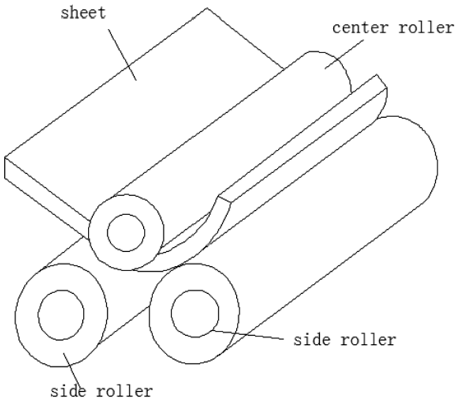
Roll forming.
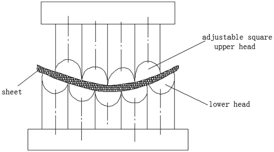
Asymmetric stamping square head adjustable die.
Hill 7 first established the exact mathematical theory of plate bending by proposing the basic theory of elastoplastic bending under plane-strain conditions and deducing the complete solution without considering the hardening of materials under pure bending conditions. Wenner 8 studied the work of hardening and the springback of sheet metal forming under plane strain. Chu 9 pointed out that the sidewall part experienced a complex bending-draw process during the forming process when he analyzed the springback problem of U-shaped parts. Based on the uniform deformation and plane-strain conditions, the isotropic follow-up hardening model was adopted. The effects of in-plane restraint, materials, and process parameters on springback were analyzed. Wang et al. 10 studied the bending springback problem of V-shaped parts and established a bending moment with material strength coefficient, a hardening index, a thickness anisotropy coefficient, plate thickness, plate width, and the convex die fillet as independent variables. The model is used to predict springback, formability, stress and strain distribution, and maximum die load during sheet metal forming. Wagoner et al. 11 established some mechanical models for describing and calculating springback predictions. Braga et al. 12 established a theoretical model of springback prediction based on an elastic pad, and its feasibility was verified through experimentations. Oliveira et al. 13 used the questions in NUMISHEET2005 as an example to study the effects of different work hardening models on the accuracy of springback prediction, indicating that the selection of material strengthening models can affect springback results. Marko et al. 14 proposed a thin-plate pure bending mechanics model that considered the thickness anisotropy coefficient r and the hardening exponent n to evaluate springback, bending, and the maximum bending moment. Chen 15 carried out theoretical calculation to calculate single curvature springback and the surface reconstruction is carried out by non-uniform rational basis spline (NURBS) method.
From the above research, the traditional analytical method has made numerous assumptions and simplifications in solving the springback problem, but it rarely considered the influence of process parameters on springback during the actual forming process, which brings a large error to the calculation results. In this article, based on the theory of medium-thickness plate bending, the theory of cylindrical and conical hull shell forming springback is discussed in detail. Based on this, an asymmetric stamping square head adjustable die forming simulation model is established. The accurate numerical simulation method is used to correct the springback curvature to effectively control springback and improve forming precision.
Theoretical calculation model
The calculations of springback are based on the theorem that the distortion caused by the unloading of a force or moment is equal to the deformation caused by the loading of a force or moment of the same magnitude but opposite direction. Therefore, the accuracy of the springback calculation depends on the accuracy of the force’s or moment’s calculations, as well as the accuracy of the moment of inertia calculations. 16
Basic assumption
According to the bending forming theory of medium and thick plates, the inner material elements stress and strain are determined by the width
When
Meet the following basic assumptions:
Plate bending process is pure bending; 16
It only undergoes elastic deformation and elastoplastic deformation, it does not undergo plastic deformation, and it satisfies the plane-strain condition, so that the strain in the width direction
There is no extrusion between the longitudinal fibers of the plate during the bending process, and there is no transverse stress between the fiber layers, and each fiber in the slat is in a uniaxially stretched or uniaxially compressed stress state;
The intermediate layer and the neutral layer are coincident. According to the mathematical theory of plastic bending, under the condition of pure bending, when the bending radius of the center layer of the plate is greater than 10 times thickness, the difference between the intermediate layer and neutral layer can be neglected, and the forming process of the bilge of the hull meets these conditions.
Mathematical model
Using the power function stress–strain mathematical model to approximate the true stress–strain relationship of the material, 18 the stress–strain relationship of the material is shown in equation (1) and Figure 3

where

Stress strain curve.
As shown in Figure 4, the material in the inner and outer shadow portions of the ship plate is plastically deformed, and the material in the middle portion is elastically deformed. 16

Three zones of plate during bending.
Moment of elastically deformation zone
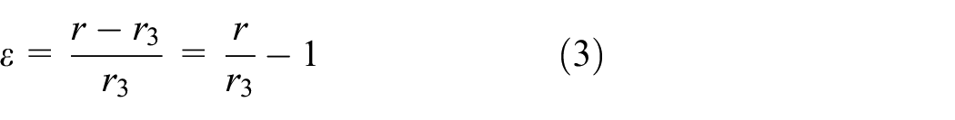
According to the theory of metal bending forming, 19 the internal strain of the plate is shown in equation (3) and the bending moment is shown in equation (4)
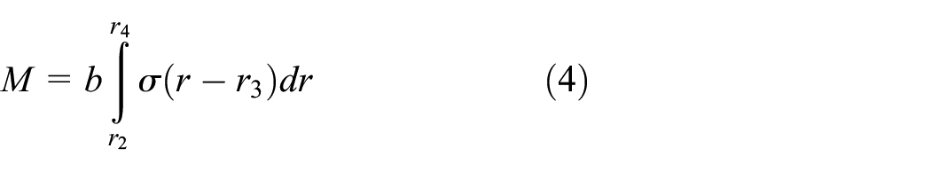
where
Submit equations (1)–(3) into equation (4) and obtain the bending moment of the elastic deformation region

Moment of elastoplastic deformation zone
Moment of plastic deformation zone on the outer side of ship plate

According to the plate strain assumption and the material incompressibility condition,

Submit equation (1) into equation (7) and obtain the plastic deformation zone to obtain the stress

Submit equations (1), (2), and (8) into equation (6)
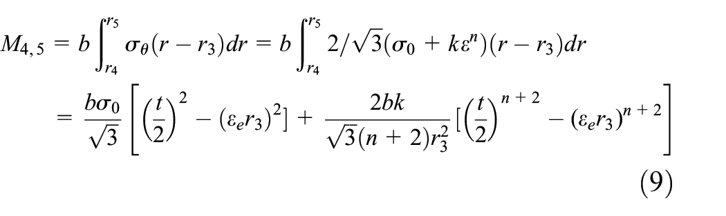
Before springback curvature
The total bending moment of the elastoplastic bending is equation (10).

The change in curvature due to springback is 19


where
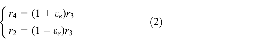
It can be known from the equation (12) that for a plate having a single curvature shape, if the material parameters, the thickness, and the target curvature are known, the springback curvature value after unloaded can be predicted. Similarly, the curvature of the target surface is taken as the curvature after springback. The curvature before springback of the upper and lower basic groups can be obtained which will improve the springbact effect by changing the target curvature.
Curvature correction coefficient
The theoretical model is based on some assumptions, which the actual springback process is affected by material parameters and process parameters (such as punching pressure, friction state, stamping speed, stamping displacement, etc.). Therefore, there will be a deviation between the actual stamping and the predicted curvature. Here, accurate numerical simulation technology is used instead of experiment.
21
Calculate the curvature correction coefficient

where
Surface reconstruction technology based on NURBS
Discrete curvature
According to the curves differential geometry theory, 22 discrete the geometric section curve of any shape plate into a segment arc and use the curvature ratio before and after springback of each arc to characterize the springback. Each discrete unit uses the bending theory to predict the curvature after springback and is corrected by the numerical simulation result. The discrete curvature of the compensation die surface required for the next pressing is obtained. Reconstruct the compensation surface and get the ideal part by trimming die and re-punching.
The key of this method is to transform the springback problem of complex irregular section stamping into the springback problem of regular equal curvature by discrete method, and obtain the compensation curvature array by curvature correction compensation algorithm. Finally, the compensation surface is reconstructed from the differential geometry algorithm of the curved curve based on the curvature data.
The bilge shells at the non-parallel middle body usually have conical surface. It can be discretized into
Discrete data
Assume that the curvature of two adjacent discrete points has been calculated, and the arc length between the two points is

where m and n are two coefficients. In order to determine the value of m and n, the curvature of two adjacent discrete points
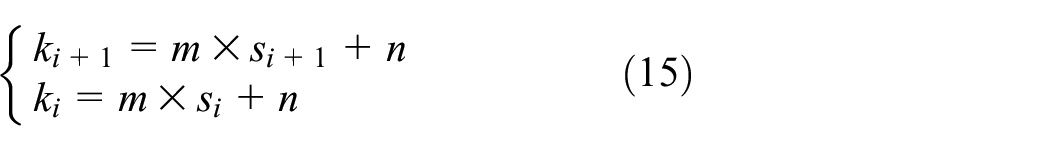
The equation (16) can be solved by equation (15)

According to the differential geometry of the curve, equation (17) is known
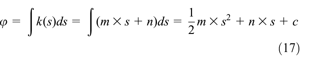
For the curve between two adjacent discrete points, the segmented curve can be further divided into a plurality of small arc segments. For the i-th segments, the expression of the curvature is obtained from equation (15), and then according to the integral equation (17) to obtain the expression of the equation (18)

Then in the i-th segment, the equation (19) is established

See Figure 5, where

Recursive curve position by curvature integral.
Then get the coordinate recursion equation (20) from
According to equation (20), the position of the curve can be obtained point by point. 23
Discrete point surface reconstruction based on NURBS
The NURBS surface equation obtained by the parameters in
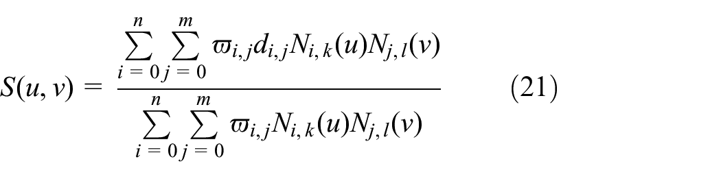
where
In this article, the NURBS method is used and the surface is controlled by the control points obtained in “Discrete data” section, so that the shape of the surface can be flexibly changed by editing the control points, and the discrete nodes are fitted into curves by NURBS method, which can improve the smoothness of the curve and get a smoother surface. CATIA software 25 is selected to surface reconstruction, which facilitates the processing of the generated surface in the subsequent steps, ensuring the consistency of the surface in the design and manufacturing process.
Springback compensation control flow chart based on NURBS is shown in Figure 6.

Springback compensation control flow chart.
Example of equal curvature springback compensation control
Numerical simulation
In order to obtain the springback curvature correction coefficient, the numerical simulation of the cylindrical sheet with a curvature radius of 2000 mm is carried out. The key techniques of numerical simulation are as follows.
Establishment of 3D model
Solidworks is used to establish a 3D model of finite element multi-point forming. There is a rotating spherical crown under the square head die, which allows the head to swing freely. In the contact stage, the remaining parts are not in contact with any part, except the upper surface of the square head is in contact with the sheet. In order to save the modeling workload and calculation time, the spherical crown behind the square head is simplified shown in Figure 7. The upper dies and the lower dies adopt a misalignment distribution. The model is established shown in Figure 8.

Simplify the head die process.

The die model.
Material properties
In the multi-point forming analysis, during the forming process the deformation of the die is small, so it is treated as a rigid body. The elements of the rigid body material are not involved in the calculation of stress and strain, and the elastic modulus and Poisson’s ratio are mainly used to calculate the contact force on the surface when the sheet and the die come into contact. The plate material parameter settings are shown in Table 1.
Properties of material.

In Table 1, R is cylindrical plate radius of curvature; B is shell width; L is shell length; t is shell thickness;
Contact conditions
The contact mode between the die and the sheet is universal contact. The friction model directly affects the calculation accuracy. The modified Coulomb friction model is used in the article. 25 This is a friction model that has been proved to be more realistic in practice. The friction coefficient is set to 0.1 in the article.
In the springback phase, in order to visually observe the springback displacement of the plate, the center point of the plate is rigidly fixed to avoid unnecessary displacement.
Unit and meshing
The plate is made of a structural hexahedron mesh, and the number of meshes is divided. The number of meshes with 1000 mm lengths on both sides is 100 and the thickness direction is 4 (see Figure 9). Since the upper and lower dies are rigid bodies, in order to reduce calculation, the mesh size is 11.6 mm and the maximum deviation factor is 0.1. The upper die mesh is shown in Figure 10. The forming stage unit type is selected as explicit, linear geometric order, C3D8R eight-node linear hexahedral element, reduced integral and hourglass control. In the springback phase unit is selected as implicit, linear geometric order, C3D8R eight-node linear hexahedral element, reduced integral and hourglass control.
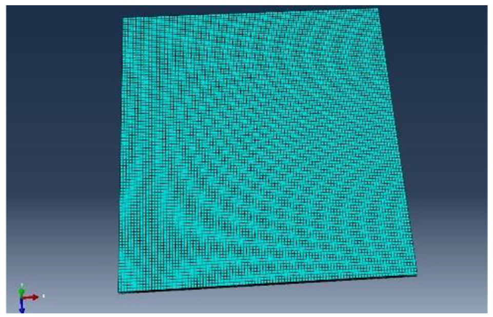
Meshing of plate.

Meshing of upper die.
Calculation results analysis
The displacement distribution cloud after springback is shown in Figure 11. The maximum springback displacement is 45.47 mm. The radius of the curvature after springback is 2412.4 mm by geometric calculation.

Displacement distribution cloud after springback.
The springback curvature correction coefficient
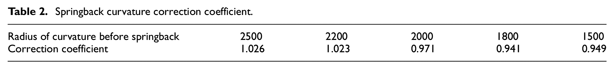
It can be seen from the Figure 11 that the springback gradually increases from the center to the edge of the shell and the maximum springback is 45.47 mm. The spline curve is obtained with a radius of curvature of about 2412 mm after springback. Using the above theoretical study, the target radius of curvature is 2412 mm and the radius of the curvature before springback should be 1923 mm. Curvature correction coefficient is 1.040. In order to improve the calculation accuracy, five sets of data are selected to average shown as Table 2, finally select the springback curvature correction coefficient is 0.982.
Springback curvature correction coefficient.
Numerical simulation verification
According to equations (5) and (9)–(13), the radius of the curvature of the Q345 plate with a target curvature of 2000 mm is calculated to be 1677 mm. In order to verify the accuracy of the theoretical calculation method, numerical simulation method is use to verify the validation. The calculation results are shown in Figure 12. It can be seen from the figure that the curvature radius before springback is calculated by the method in this article, and the curvature after springback is very close to the target curvature.

Forming result shape comparison.
Experimental verification
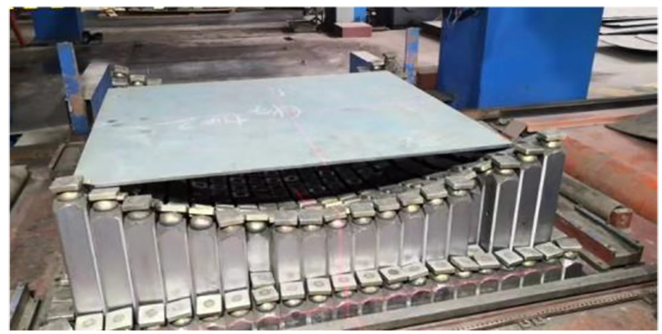
The springback experiment of Q345 plate with a curvature radius of 1677 mm was carried out. Import the prepared experimental data into the instrument, and the instrument will automatically adjust the position of the lower dies according to the data. After the completion of the profile adjustment, the lower dies will form a certain curved surface, as shown in Figure 13.

The lower dies curved surface.
In the process of shape adjustment, the indenter moves vertically, the indenter plane is horizontal, and the surface formed is not completely smooth. In the process of pressing, the indenter will rotate under the force of the upper indenter and finally fit into a better surface. Then fix the plate on the formed die, as shown in Figure 14, and operate the upper indenter to lower and compact, as shown in Figure 15. After pressing, keep the pressure for a certain period of time to prevent the plate from springback immediately. The effect after pressing is shown in Figure 16. It can be seen that the non-symmetric pressure head can still be successfully fitted into a suitable surface. In addition, compared with other types, there is no need to add special blank holder around the plate.
The plate on the lower dies.

Plate is compacted by dies.

The effect after pressing.
The measurement is carried out after pressing. Figure 17 shows the comparison between the measurement results of the laser measuring instrument and the target surface. Red is the measurement value and black is the theoretical value. The other is to measure on the surface with the already made template. Figure 18 is to measure with the template.

Measurement results of the laser.

Measure with the template.
After the experiment, the radius of curvature measured after springback is 2025mm, while the radius of curvature calculated by theory is 2000mm, the relative accuracy is 98.77%, which meets the requirements of process accuracy.
Example of variable curvature springback compensation control
The bilge of a ship in a non-parallel middle body is a conical surface. Its properties of material are same as Table 1. The partially discrete curvature along the length direction is shown in Table 3. The target shape is shown in Figure 19.
Partially discrete curvature along the length direction.

Target surface shape.
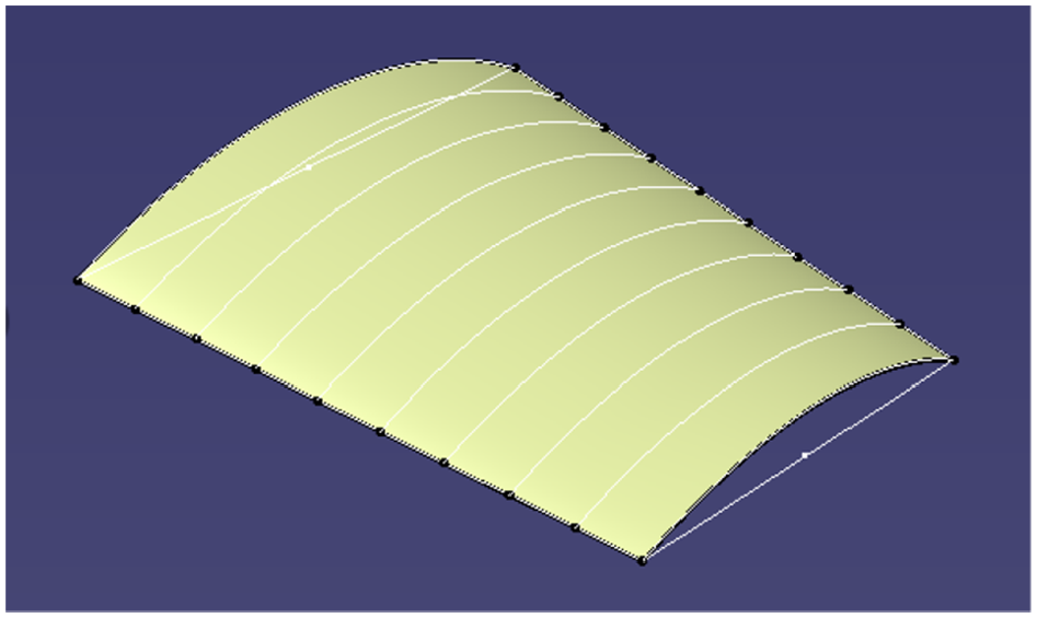
The linear interpolation method is used to discretize the curvature. Based on the two-dimensional springback calculation theory, the radius of the curvature before springback of each discrete section is obtained, and the above-mentioned curvature-based surface reconstruction method is used to obtain the discrete points. Some data are shown in Table 4. CATIA 26 method is used for surface reconstruction shown in Figure 20. The surface shape before and after springback is shown in Figure 21.
Discrete data points before springback.


Curved surface shape before springback.

Surface shape before and after springback.
Conclusion
Although the theory of two-dimensional sheet metal forming is a traditional topic, with the continuous development of mechanization, intelligence and simulation technology, the forming equipment is constantly updated. The theoretical calculation model of sheet metal forming is corrected based on the advanced equipment of asymmetric pressure square head CNC cold bending machine. The following conclusions can be obtained by calculations.
We can find the theoretical springback formula has a certain range of application, from equation (9). When the radius of the curvature is greater than 4770 mm, the plastic deformation is small and the moment of plastic deformation zone on the outer side of ship plate is negative value. This formula will go beyond the scope of use and no longer valid.
Forming theory is unlikely to produce very accurate springback results, but it is very close to the desired result, so that the times of stamping can be reduced as much as possible and improve the processing efficiency.
In addition, the results of theoretical analysis and simulation need to be verified by a large number of experiments. The theoretical model and the finite element model should be corrected by the results of the experiments, and finally a more accurate model will be obtained. Due to time and cost, only some experimental data have been added in the article. In the next work, we will use more experimental data and accurate numerical simulation algorithm, and try to apply the theory and method of two-dimensional sheet metal forming to three-dimensional sheet metal forming.
Footnotes
Handling Editor: Alberto Martini
Declaration of conflicting interests
The author(s) declared no potential conflicts of interest with respect to the research, authorship, and/or publication of this article.
Funding
The author(s) disclosed receipt of the following financial support for the research, authorship, and/or publication of this article: The work presented is supported by Natural Science Foundation of China (51609031) and China Scholarship Council (No. 201806575010).