
Abstract
In this article, a finite element model of multi-layer composite laminates with delamination based on higher order zig-zag theory is studied for the progressive delamination analysis. The degrees of freedom are simplified by the continuity conditions of shear stress between layers and the free-surface conditions at the bottom and top of laminates. The numbers of degrees of freedom are not reduced with this method while the model can take the initiation of delamination into consideration in return. Static loading analysis is implemented to simulate the performance in delamination resistance with two different plies and under two different boundary conditions. The present model can present good performance in the prediction of delamination phenomenon.
Introduction
Nowadays, composite materials have been applied extensively in many industrial fields such as aerospace, chemistry, automobile, sport apparatus, and medical instruments, attributing their high specific strength and stiffness, good fatigue and corrosion resistance, and property designability. These merits make them occupy a superiority position in competing against conventional materials. The laminated composite is the most common used composite in various composite structures.
Failure or damage mode of composite material is complex compared with homogeneous material, for example, metal or alloy, attributing their multiphase microstructures. The failure mode of composite laminate is usually classified into three types: fiber failure, matrix failure, and delamination. Failure theories in early stage, for example, Tsai-Wu criterion, 1 are usually phenomenological ones which do not distinguish damage mode in detail. Hashin 2 proposed a well-known failure law in which damage mechanisms for different component phases are distinguished. Puck 3 developed Hashin’s work, and their model with the angle of fracture plane can predict unidirectional (UD) composite under transverse compression by introducing a function called the stress exposure factor. A lot of works4–9 have been implemented to verify the reasonability and reliability of their theory numerically and experimentally. In numerical simulation, appropriate material properties degradation should be employed to reflect the residual stiffness or strength of damaged composite corresponding to different failure modes or even for the needs of computing stability. YS Reddy and JN Reddy 10 suggested a stiffness coefficient which resulted good agreements with experiments. Hashin criterion was employed by Hwang and colleagues11–13 and Camanho and Matthews 14 to predict failures of fiber, matrix, and delamination while considering stiffness reduction.
Composite are usually used in thin wall structures; plate and shell theory is an efficient tool for mechanical analysis of these structures. The traditional Kirchhoff thin plate model neglect of transverse shear strain (stress) and normal stress along thickness, which actually have important contributions to delamination damage of composite laminates. For improvements, first-order shear deformation theories (FSDT) 15 and higher order shear deformation theories (HOSDT) were proposed considering the transverse shear stress. Normal stress in the direction of thickness was studied by Pagano 16 and Whitney and Sun. 17 M Aydogdu 18 developed a new displacement mode for laminated plates considering transverse shear deformation and got improved static and dynamic results. Furthermore, Reddy et al. 19 developed a layerwise theory for improving accuracy of multi-layer composite structure. In order to aise computing efficiency, the zig-zag theory was proposed by Lekhnitskii, which has demonstrated conspicuous advantage in hierarchical stress and transverse shear analysis for laminated structures. Zig-zag theories have developed various displacement modes and used that to different problems in recent years. Ambartsumian 20 applied parabolic functions to derive transverse shear stress distribution; YB Cho and RC Averill 21 used a discrete first-order zig-zag theory (FZZT) to analyze laminate and sandwich beam. U Icardi 22 deduced an eight-node zig-zag element; Oh and Cho 23 made an attempt to analyze thermo-electric-mechanical coupled smart composite plates with higher order zig-zag theory (HZZT). By adding step functions, zig-zag theories can employed in delamination damage analysis of composite laminates, which can be found in works of U Icardi 24 and RMJ Groh and A Tessler. 25
For delamination analysis, virtual crack closure technique (VCCT), cohesive zone modeling (CZM) and extended finite element method (XFEM) are three of the commonest methods to analyze problems about crack propagation and delamination. VCCT was proposed by Irwin. 26 The VCCT associates the nodal force with displacements around the crack tip. By this method, the strain energy release rate can be easily obtained. Davidson et al. 27 established composite laminate model to study the fracture toughness of mode I and mode II crack with VCCT. Kaczmarek et al. 28 used three-dimensional (3D) VCCT to analyze the delamination at the boundary of laminates. CZM is based on the relative displacement between the upper and lower surface of crack and uses fracture toughness to judge failure. CZM was first proposed by Dugdale. 29 This method includes all three modes of delamination and the constitutive relationship is very simple. Many researchers simulated delamination propagation with CZM and developed CZM. Comanho et al. 30 used CZM to do numerical simulation of delamination propagation. Robinson et al. 31 utilized CZM to deal with the problems about crack propagation under fatigue load. Fan et al. 32 proved that CZM performs well in the analysis of delamination propagation in double cantilever beam (DCB) compared with experiments. The main idea of XFEM is to add additional degrees of freedom to nodes to express the information related to cracks. Motamedi and Mohammadi 33 did the dynamic analysis to laminates with XFEM. Ashari and Mohammadi 34 analyzed the problems about intra-laminar and inter-laminar crack. Wang and Waisman 35 developed XFEM with CZM to study delamination propagation.
There are still not much delamination analysis which is applied on HZZT. In this article, a method to process the inter-laminar normal stress is proposed. A displacement mode based on HZZT is presented which can provide continuity of transverse stress and discontinuity of displacement at the interface of layers where delamination happens. The numerical investigation for evolutions of multi-damage including delamination in laminated composite plate was carried out.
Theoretical foundation of HZZT
Displacement formulation of HZZT
A displacement model of HZZT satisfying two basic conditions, that is, free of transverse on two surfaces of plate and continuity of transverse shear stress along thickness, was proposed by M Cho and JS Kim 36 which can describe multi-delamination of composite laminate. The displacement of this theory is formulated as follow (Figure 1)


Schematic of HZZT: (a) geometry of the model and (b) deformed configurations.
The plane where

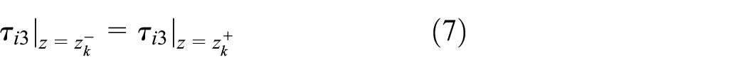
On the two surfaces

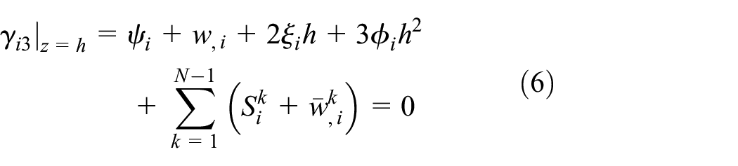
where
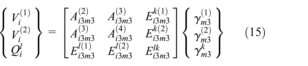
Through combining constitutive relation of laminates,

where


The concrete definition of the coefficients can be found in Appendix 1.
Stiffness matrix of HZZT
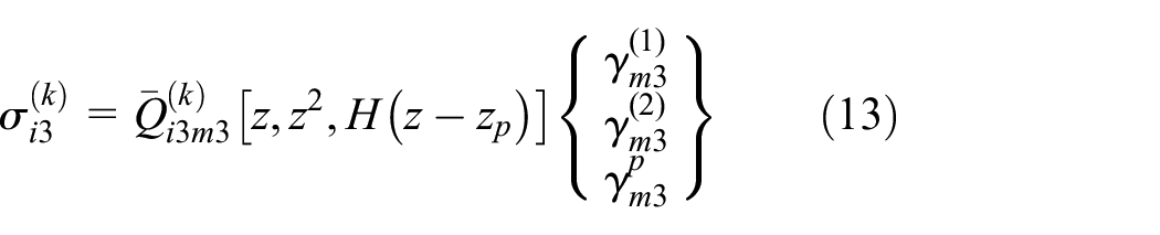
In a laminate coordinate system, the resultant forces for each ply in composite laminate relate strains of this ply via stiffness matrix

where the superscript

Integrating the stresses above along the thickness of laminated composite plane, the resultant force of composite is obtained as follows 36
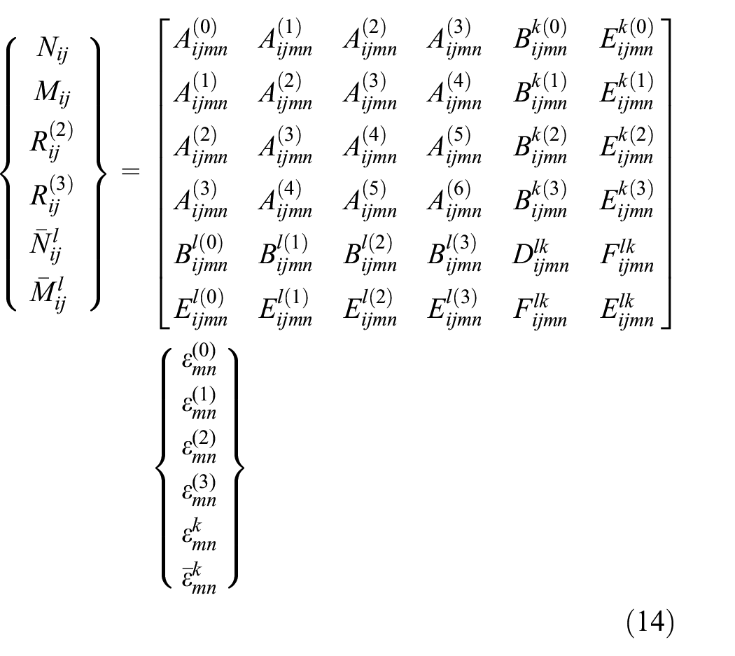
where
Finite element scheme of HZZT
In finite element scheme of HZZT, the displacement vector of a node for an element is

where
The components in equation (16) are defined as with Lagrangian and Hermite interpolations
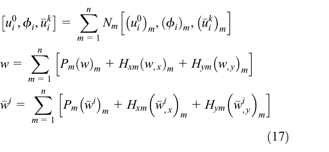
where


The expressions of sub-matrixes in the strain-nodal displacement matrixes above are found in Appendix 3.
Multi damages models of composite
Intra-laminate damage modes
3D Hashin criterion is employed to predict the initiation of damage

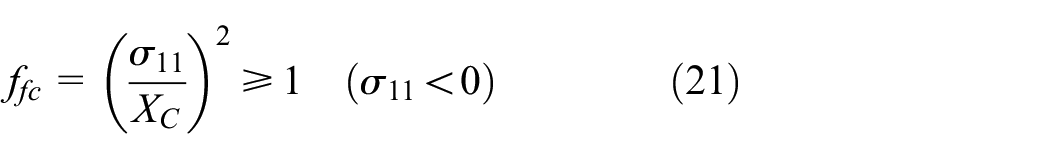


Equations (20)–(23) are failure criteria for modes of longitudinal tensile failure, longitudinal compressive failure, transverse tensile failure, and transverse compressive failure, respectively.

As the damage occurs, the engineering constants of the material are declined with the coefficient, as given in Table 1.
Stiffness degradation under different failure modes.

Inter-laminate damage modes
The delamination failure criteria is applied as equation (25)
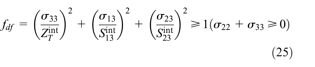
where

where


where

Model of off-plane spring bonding adjacent plies.
Implementation in finite element frame
The damage criteria mentioned above have been implemented in HZZT element on platform of user-defined element (UEL) of general element code Abaqus. If the in-plane damage occurs, the relevant terms in stiffness matrix will be degraded. It needs notice that for an perfect interface between adjacent plies, the freedoms relevant with delamination are forced zero
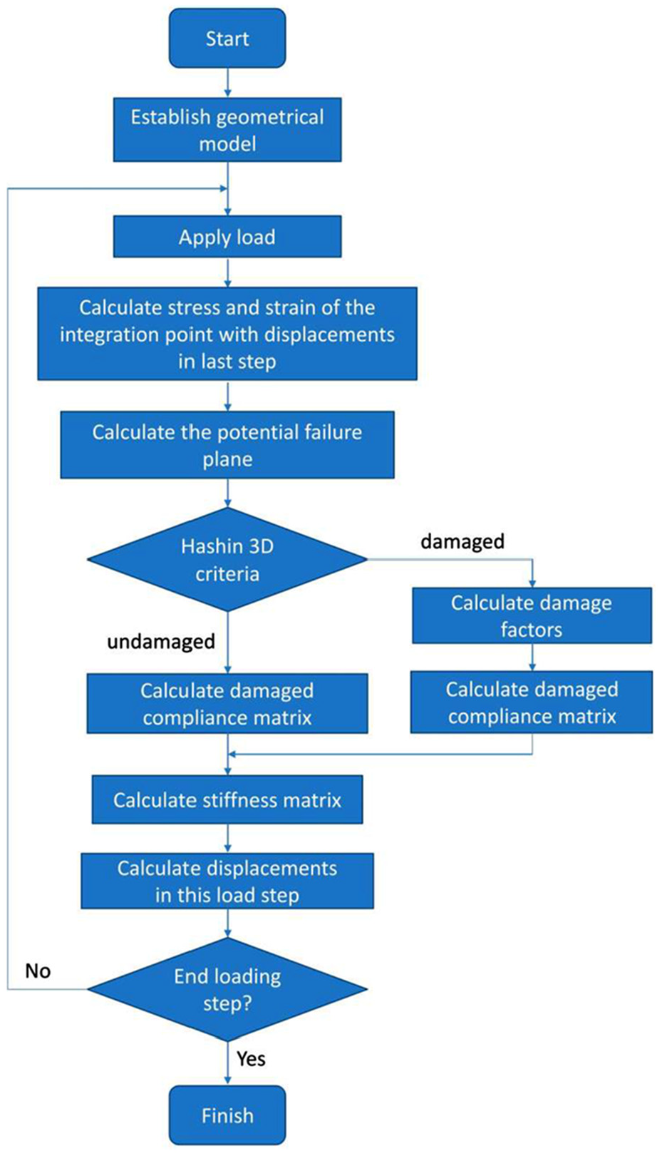
Flowchart of progressive damages of HZZT.
Numerical models
Double cantilever beam
To validate the proposed HZZT in this part, simulation of delamination propagation in DCB is conducted. The model is constructed according to Heidari-Rarani and Sayedain. 38
The dimension of the specimen is

Dimension and boundary (loading) conditions of the DCB specimen.
Elastic constants of single ply 1.

Orthogonal ply composite laminates
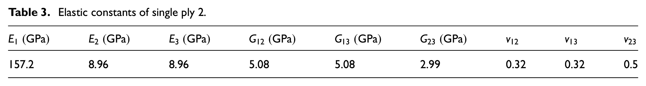
Carbon fiber–reinforced epoxy matrix composite laminates are employed to validate the HZZT approach proposed in this article. The elastic constants and strength parameters of single ply of this composite are listed in Tables 3 and 4, respectively. Two ply patterns are used, that is, (0°, 90°, 90°, 0°) and (45°, –45°, –45°, 45°), which are shown in Figure 5, and they are named ply pattern 1 and ply pattern 2, respectively; the thickness of each ply is 0.25 mm. The dimensions of the two plates of composite laminates are both 101 mm × 101 mm with the thickness of 1 mm, and they are discretized to square HZZT elements with size 1 mm × 1 mm. The plates are applied two antisymmetric uniform distributing loads on one side, as illustrated in Figure 6; the loads form a torque which will cause interlaminar shear stress in composite laminate. Two boundary conditions are used: one case is that the side opposite to load-applied edge is clamped and the two other sides are free; the other case is that the three sides except the load-applied edge are all clamped, as illustrated in Figure 6.
Elastic constants of single ply 2.
Strength parameters of single ply.


Ply patterns of the composite plate: (a) ply pattern 1 and (b) ply pattern 2.

Loading and boundary conditions of the composite plate: (a) one edge clamped and (b) three edges clamped.
Loads with 0.05 N/m increased per step are applied to the composite laminates with different ply patterns and different boundary conditions as Figures 5 and 6 show. The definition of interface is demonstrated in Figure 7.

Definition of interface.
Results and discussion
Mode I interfacial debonding DCB
In this section, load-open displacement curves obtained from DCB model built in section “Double cantilever beam” is illustrated in Figure 8, and results from experiment 39 and from other models 38 are also presented in Figure 8 for comparison. The load–open displacement curves show linear pattern during the initial loading stage because the interfacial damage is not severe and the interfacial crack length is considered nearly invariable in this stage. When the delamination propagates, the load declines as the open displacement increases.

Comparison of load-open displacement curves of DCB specimen from proposed model, experiment and other models.
As Figure 8 shows, all numerical models fit well with the experimental result in initial stage, but they all over estimate the maximum load capacity compared with experiment measurement. This is explained that for real scenario, interfacial damage occurs earlier than model predictions, and besides, the bridge effects at debonding crack tip might retard the ultimate interface separating. The numerical models, however, do not consider the bridge effect and the complete debonding occurs in sudden way in one element scope. Therefore, the experimental curve exhibits obvious slope reduction before it reaches load peak and it drops from peak point in a more gentle way than model predictions. During the softening stage, the proposed model, and methods of CZM 2D 38 and XFEM-CZM, 38 agrees well with experiment data. Compared with other numerical methods, the HZZT model developed in this study either gives prediction with the same accuracy level of existed models, or it can be built more conveniently.
Multi-mode progressive damages of composite laminates
For case of one-side clamped boundary condition, delamination damage evolutions are illustrated in Figures 9–11. Figure 9 shows the delamination of interface 1, which is counted from bottom surface to top surface as Figure 7 shows. Interfacial damage occurs first at the clamped edge as shown in Figure 9(a), and then it appears at the bending load edge (Figure 9(b)), with load increasing as the existed delamination areas extend and new ones are found in inner region (Figure 9(c)), when load reaches q = 0.9 N/m and almost 85% area of interface 1 fails.Figure 10 is the interfacial damage in the same interface for ply pattern 2. The damage also begins at clamped edge but it extends slower than ply pattern 1. Figure 10(b) shows obviously better performance in delamination resistance than that in ply pattern 1 which is shown in Figure 9 even under much larger load. For the interface 3, however, the delamination at load side is severer than clamped edge as shown in Figure 11(a), then the delamination areas will connect each other with load increasing. For the three sides clamped boundary condition, the interfacial failure of interface 1 for ply pattern 1 starts at the corner of the loading side and then appears at middle of this side, as shown in Figure 12(a) and (b). When load increases, these two delaminated areas extend, connect together with other and isolated interfacial crack areas emerge successively (Figure 12(c) and (d)). Figure 13 shows the delamination evolution in this interface for the ply pattern 2. The delamination is also found at corner of load side (Figures 13(a) and (b)), and subsequently interfacial damage merges at other place of load side (Figure 13(c)), and then takes place in clamped sides and other isolated regions (Figure 13(d)).

Delamination development of interface 1 in one side clamped composite laminate of layer pattern 1: (a) q = 0.35 N/m, (b) q = 0.45 N/m, (c) q = 0.7 N/m, and (d) q = 0.9 N/m.

Delamination development of interface 1 of one side clamped composite laminate of layer pattern 2: (a) q = 0.45 N/m and (b) q = 1.5 N/m.

Delamination development of interface 3 in one side clamped composite laminate of layer pattern 2: (a) q = 0.7 N/m and (b) q = 1.5 N/m.

Delamination development of interface 1 in three sides clamped composite laminate of layer pattern 1: (a) q = 0.35 N/m, (b) q = 0.45 N/m, (c) q = 1.2 N/m, and (d) q = 1.3 N/m.

Delamination development of interface 1 in three sides clamped composite laminate of layer pattern 2: (a) q = 0.35 N/m, (b) q = 0.45 N/m, (c) q = 0.8 N/m, and (d) q = 1.3 N/m.
Conclusion
In this article, HZZT is employed and developed for analysis of multi damages (especially for delamination) in composite laminates. It concludes that
HZZT is developed to calculate off-plane normal stress by introducing springs at element nodes which bonds with the adjacent plies. The off-plane normal stress is important (for some loading scenario it is the must) for debonding estimation of composite laminate, but however, it is absent in traditional zig-zag models. Therefore, the development made in this study widely extends the application cases of HZZT.
The HZZT developed in this study is used to predict load–displacement behavior of a composite DCB, and its prediction agrees well with experimental data and results from other numerical models. Besides, it has advantage in convenience of model building compared with other existed numerical models.
When one side of the laminate is clamped and the opposite is loaded with anti-symmetric uniform load, the delamination usually occurs at the corner connecting clamped border and load free edge initially and then takes place at the loading area.
Laminates with three sides clamped usually delaminate at the free side with loads.
Delamination areas can spread and intend to join together with the increase of the damage area.
Ply pattern in (45°, –45°, –45°, 45°) may have better delamination resistance than that in (0°, 90°, 90°, 0°).
Footnotes
Appendix 1
The coefficients in equations (9) and (10) are
And according to constitutive equations, the strain tensor can be shown as
where
Appendix 2
The expressions of elements in stiffness matrixes in equations (14) and (15) are
Appendix 3
The expressions of sub-matrixes in the strain-nodal displacement matrixes in equations (19) and (20) are
and
Handling Editor: José Correia
Declaration of conflicting interests
The author(s) declared no potential conflicts of interest with respect to the research, authorship, and/or publication of this article.
Funding
The author(s) disclosed receipt of the following financial support for the research, authorship, and/or publication of this article: This work was supported by Postgraduate Research & Practice Innovation Program of Jiangsu Province (Grant No. KYCX18_0251), National Natural Science Foundation of China (Grant Nos 11872205, 11272147), SKL Open Fund (Grant No. MCMS-0218G01), and Priority Academic Program Development of Jiangsu Higher Education Institutions.