
Abstract
The operational performance of the spiral spring energy storage system is affected by the vibration of the spiral spring and the electrical loss of the permanent magnet synchronous motor. It is important to eliminate vibration and reduce electrical loss. A unified control scenario for speed regulation and vibration suppression based on the minimum electrical loss is proposed. First, the spiral spring is equivalent to an Euler–Bernoulli beam and its dynamic model suitable for control is established via the Lagrange equation. Then, the unified control scenario is proposed through nonlinear backstepping control. The speed controller and current controller including modal vibration suppression and minimum electrical loss operation of the system are established, and the stability of the controller is theoretically proved. Moreover, for unknown vibration mode of the spiral spring, a vibration mode–based estimation method with the least-squares algorithm is designed. Aiming at the uncertainty of the permanent magnet synchronous motor’s iron loss resistance, an estimation algorithm based on an adaptive neural fuzzy inference system is designed. The experimental results verify the correctness and effectiveness of the proposed control scheme. In comparison with traditional backstepping control, the proposed control method can effectively suppress the vibration of the spiral spring and realize the stable and highly efficient energy storage operation of the system.
Keywords
Introduction
The basic goal of a modern power system that is to operate in the way of cleanness and high efficiency promotes the bulk of new energy sources to connect to the grid. However, natural characteristics of randomness in time and fluctuation in space for new energy sources have been changing the traditional operation mode of controllability and adjustability in the supply side of the power system, 1 which will trigger or exacerbate the issue of power imbalance in the grid. One of the most effective ways of addressing the problem is to develop the technology of energy storage. Spiral spring energy storage (SSES) is a newly proposed way in recent years with various superiorities of large power density, high performance–cost ratio, long life-time, and nonpollution.2–5 In general, the spiral spring is manufactured with a slender material and wound up in the shape of a spiral curve. For storing energy as much as possible, the length of the spring is significantly larger than its width and thickness. For instance, the length of the spring in the research is about 292 times the width and 7982 times the thickness. When tightening the spring, its shape is changed continually. It will appear to be flexible and different from its rigidity in the free state. Previous studies 6 uncover the fact that this type of object will show natural vibrations with a low frequency and a high amplitude under the action of external bending moment.
Actually, several types of flexible loads are in use for various industrial fields, 7 such as flexible linkage mechanism, series elastic actuator, and gear drive system. A two-inertia system is generally used to model these flexible loads 8 and the control approach consists of active control and passive control. Active control means that the vibration is removed from the source by designing the controller. State feedback control based on proportional–integral (PI) or pole configuration is typical, and the acceleration- or torque-based feedback control method is also popular. 9 However, various PI-based active feedback control methods require empirical configuration of PI parameters, 10 and fixed PI parameters have poor adaptability to structural adjustment and parameter variation that easily lead to weak control performance. Passive control is to deploy a suitable filter or notch filter between the speed loop and the current loop to suppress the vibration, such as the notch filter of frequency and low-pass filter. 11 However, filters with a fixed frequency band could only eliminate the system’s vibration in a certain frequency band and also limit the system’s frequency band, thus resulting in phase lag. It can be seen that the application of a two-inertia elastic system has a certain foundation for flexible joints, but it is inaccurate to describe the large-sized flexible SSES system. Studies have shown that a slender and long beam with a Lagrange equation can be used to construct the dynamic model of a spiral spring12–14 and obtain its natural frequency and modal response of long beam oscillation. Besides, the model of the spiral spring could also be built through a finite element software like ANSYS, and vibration modes of the spring are directly obtained by applying loads.15,16 One of the superiorities for these modeling methods is to reveal vibration modes of the spiral spring precisely, but they pay close attention to mechanical properties and it is hard to combine with the motor to study the electromechanical property and is also unable to eliminate the influence of the spring’s mechanical vibration on the system.
Currently, the flexible load is basically driven by a stepper servo motor in view of its merits of low cost and being convenient to control. Merely, the stepper motor is dependent on open-loop control with low accuracy, and the vibration of a flexible load is more likely to be excited.17–19 Due to the advantages of simple structure, easy maintenance, and large torque at startup,20,21 a permanent magnet synchronous motor (PMSM) replacing a stepper motor is used as the device to drive the SSES system. 22 For an energy storage system, operating efficiency is a key indicator that should be focused on. 23 Iron loss and copper loss that exist in the PMSM affect the operating efficiency of the whole system. It is essential to control the PMSM running at a minimum electrical loss. At present, some studies have investigated minimum electrical loss control of a PMSM, but there are fewer articles on which the identification of iron loss resistance is further considered. A search-based identification method is proposed in Tripathi and Dutta 24 to realize minimum electrical loss control by deducing the current relationship with d−q axes at minimum loss. The experimental result shows beneficial effects both in identification and in control. In Oussama et al., 25 an algorithm of stator resistance estimation with a sliding mode observer for a PMSM is presented. In Lee and Ha, 26 the PMSM drive system with a single-inverter dual parallel configuration and maximum torque per ampere (MTPA) control minimizes operating losses by controlling the d-axis current of the motor. It can be seen that the influence of iron loss resistance on minimum electrical loss is often neglected in some literature, which results in an inaccurate total loss in reality to a certain extent. On consideration of the close relationship between iron loss resistance and variables of frequency and motor speed, the variations of frequency and motor speed will generally change iron loss resistance, thereby affecting electrical loss. Although iron loss resistance could be estimated online accurately, it will take much higher calculation time, occupy a large amount of storage space, and may lead to a certain delay in outputting the result.
Therefore, the control problem in this context could be described as follows: The PMSM in an optimal efficiency is regulated to run at a suitable speed to tighten the spring securely, and simultaneously the vibration of the spring is inhibited. Due to nonlinear characteristics of modeling a PMSM in a multivariable, high-dimensional, and strong coupling, the variation of the system’s operating state, and the inherent feature of the spiral spring in vibration and deformation, it is difficult for traditional control methods to meet the requirements of high precision, low loss, and high efficiency. It is of great significance to study a new control scheme. Backstepping control is a nonlinear control approach being popular in recent years. Over some backward steps, one or more virtual control variables are designed to transform a high-dimensional nonlinear plant into a low-dimensional linear plant. Currently, backstepping control has been successfully applied to the PMSM in the areas of vector control27,28 and direct torque control, 29 but it is rare to find backstepping control to suppress the vibration of the flexible load while improving the system’s operation efficiency.
In allusion to the control problem in the context, the overall system model of the PMSM actuating flexible spiral spring load with variable torque, large size, and inertia is to be established based on the Lagrange equation. Then, based on realizing the minimum electrical loss condition through the Lagrange equation, two backstepping controllers of speed and current are designed to regulate the speed of the PMSM and suppress the vibration of the spring. Meanwhile, due to the uncertainties of the vibration mode and iron loss resistance, different estimation algorithms are devised to identify the vibration mode and iron loss resistance, respectively. The correctness and effectiveness of the control scheme are verified by various hardware experiments.
The innovations of this article are threefold: First, the Lagrange equation is used to establish a dynamic equation of the spiral spring considering the vibration mode for the first time. Second, an integrated control scheme of speed regulation and vibration suppression based on nonlinear backstepping control for the PMSM directly driving flexible load is proposed with consideration of minimum electrical loss of the PMSM. Third, an estimation method based on the least-squares algorithm for the spiral spring’s vibration model is designed, and a method based on an adaptive neural fuzzy inference system (ANFIS) is designed to identify iron loss resistance.
The arrangement of this article is as follows: Section “System modeling” introduces the modeling of the system. Section “Minimum electrical loss control and vibration suppression based on backstepping control” proposes a control scheme that simultaneously suppresses the load vibration and improves the operating efficiency of the system. The mode of the spiral spring for vibration identification based on the least-squares algorithm and the identification of iron loss resistance through the ANFIS is shown in section “Identification of the modal vibration of the spiral spring and iron loss resistance of the PMSM.” The experimental analysis is covered in section “Hardware experiment and result analysis.” Finally, the section “Conclusion” presents the conclusion.
System modeling
Mathematical model and loss modeling of the PMSM
When a surface-mount PMSM is selected as the driving motor, many studies often ignore its iron loss that occupies a certain proportion in the total loss. Actually, the total loss of the PMSM mainly consists of iron loss, copper loss, and mechanical loss. Since mechanical loss is related to bearing friction, material property, and ambient temperature, it is not convenient to measure and is merely a small percentage of the total loss. Therefore, this research neglects mechanical loss and focuses on controllable losses of iron loss and copper loss. Here, dq-axis equivalent circuits of the PMSM are established and shown in Figure 1.

dq-axis equivalent circuits of the PMSM: (a) d-axis equivalent circuit and (b) q-axis equivalent circuit.
In the dq0 rotating coordinate system, the mathematical model of the PMSM can be described as30,31

The electromagnetic torque equation is

where ud and uq are the stator voltages in the dq-axis, id and iq are the stator currents in the dq-axis, iwq and iwd are the active components in dq-axis currents, Ld and Lq are the stator inductances in the dq-axis, ψr is the permanent magnet flux, Rs is the phase resistance of the stator winding, np is the pole pair number of the rotor, ωr is the mechanical angular velocity of the rotor, and Te is the electromagnetic torque.
In terms of the equivalent circuits of the motor, we can obtain
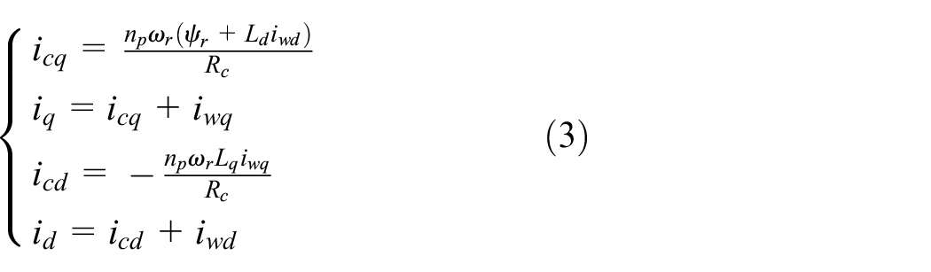
where icd and icq are the iron loss components in dq-axis currents.
Substituting equation (3) into equation (1), we can obtain

The expressions of copper loss PCu and iron loss PFe in the electrical loss for the PMSM can be obtained from Figure 1 as follows

Substituting equations (2) and (3) into equation (5), the total electrical loss Ploss is given by

Vibration model of the spiral spring
The point o is the connection point between the shaft of the PMSM and the spiral spring, and the point o′ indicates the origin of the cross-section in the connection point o. The schematic diagram of the PMSM driving the spiral spring is shown in Figure 2. The moving coordinate system xoy follows the rotation of the rotor. The coordinate system x′o′y′ is stationary, and s(x, t) is the displacement in the moving coordinate system xoy depicting the deflection of the spiral spring x deformed by the external bending moment TL. θr is the angle at which the PMSM rotor rotates.

Structural diagram of the spiral spring driven by the PMSM: (a) system configuration diagram and (b) PMSM and spiral spring connection diagram.
It is assumed that the spring is formed by bending a slender strip into the spiral shape. The beginning of the spring is directly connected to the shaft of the PMSM, and its end is fixed. The length of the spring is much larger than its cross-sectional dimension. In this study, only the lateral vibration of the spring is considered and the longitudinal vibration is ignored. The spring is regarded as an Euler–Bernoulli beam. Then, the vibration equation of a spiral spring can be expressed as32,33

where E is the elastic modulus, ρ is the mass density, I is the area moment of inertia, b and h are the width and thickness, respectively, Sp is the cross-sectional area of the spring, and f(x, t) is the distribution force acting on the spring. For the spiral spring with a rectangular cross-section, I = bh3/6.
The boundary conditions of the spring are

where L is the length of the spring.
In terms of the vibration theory, the displacement s(x, t) can be written as
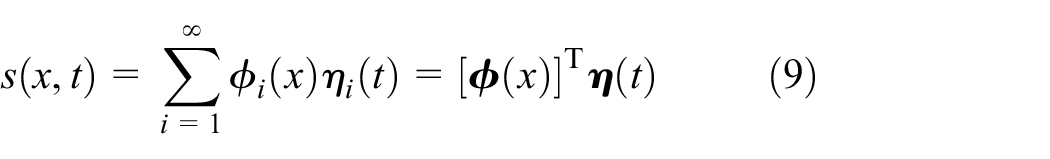
where
In order to solve the vibration mode
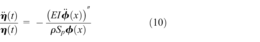
It can be seen that the left-hand side of equation (10) is an expression only with time t, and the right-hand side of equation (10) is an expression only related to the coordinate x. Therefore, the solution of equation (10) should be a constant and it is supposed to be −c2. So the modal function and modal coordinate are solved as follows

Equation (11) can be simplified availably

where
The corresponding eigenequation of the modal function is

More specifically, the modal function
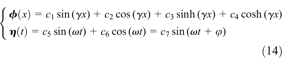
Substituting the boundary condition (equation (8)) into equation (14), we can obtain
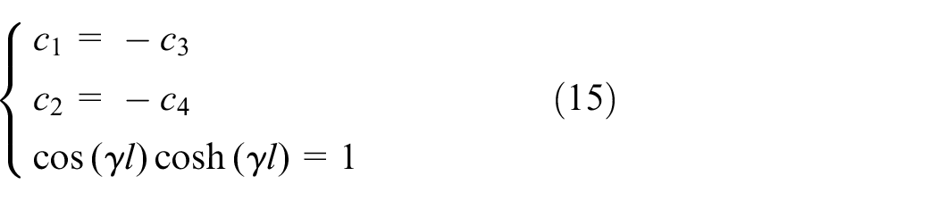
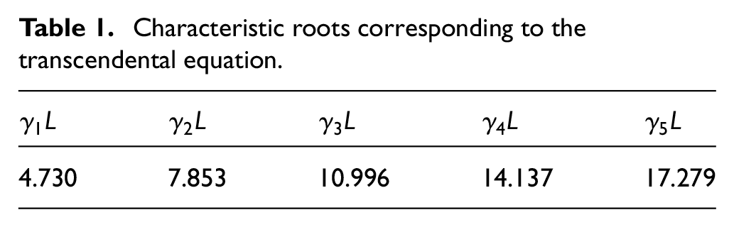
γ = 0 is a solution of equation (15). Since it corresponds to the stationary state of the spring, it should be discarded. Through some numerical calculations, the lowest eigenvalues of this transcendental equation could be found and are shown in Table 1.
Characteristic roots corresponding to the transcendental equation.
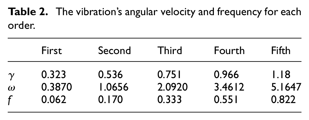
The angular velocity of the spring in vibration is obtained by equation (7)

According to equation (16), the vibration’s angular velocity and frequency for each order are shown in Table 2.
The vibration’s angular velocity and frequency for each order.
Ignoring the modalities after the Nth order, the displacement s could be given by

For any point P on the spiral spring, if the PMSM is tightening the spring, its coordinates (XP, YP) are shown as

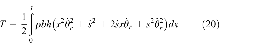
When the spring is wound up by an external force, the generated kinetic energy T could be written as
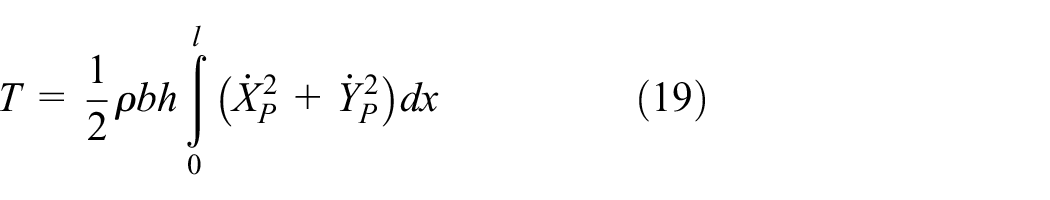
Simplifying and rearranging equation (19), we can obtain
Meanwhile, the potential energy V that represents the elastic energy produced by elastic deformation of the spring is

The Lagrange equation is formulated as follows

where Qi is the external force, q1 is the rotor’s rotation angle θr, and qi
q 1 satisfies the following equations
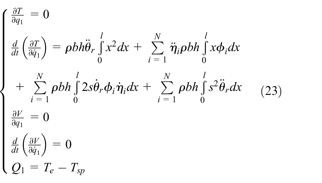
In terms of equation (22), equation (23) can be written as

where Tsp is the torque of the spring given by Tsp = ksp·θr, with ksp being the spring constant. Since s is relatively small, the expression of two product terms related to s in equation (24) could be ignored.
Similarly, for qi, we obtain

That is

Letting

Overall system mathematical model
In practice, because the first-order modal vibration dominates the vibration of the spring, higher-order modal vibrations have relatively less influence. 6 Meanwhile, according to the modal truncation criterion, the impact of the higher-order mode on the overall system is also small. Therefore, only the first-order modal vibration is considered, and integrating equation (24) with equation (27) we could obtain

Letting

Minimum electrical loss control and vibration suppression based on backstepping control
Minimum electrical loss realization condition gained through Lagrange equation
For an optimization problem, the applications of the Lagrange multiplier and Karush–Kuhn–Tucker (KKT) conditions are the two most common methods. The KKT condition is selected to solve unequal constraints. The Lagrange multiplier method is used when there exist equality constraints. Because of the equality constraint (equation (2)), the Lagrange multiplier method is used in this article.
Lagrange multiplier λ is introduced and the auxiliary function is built as follows
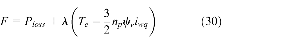

The above equation is used to obtain the partial derivatives of iwd, iwq, and λ, respectively, and shown in equation (31).
Letting all the above equations be equal to zero, the d–q axis active currents under minimum electrical loss control can satisfy the following relationship

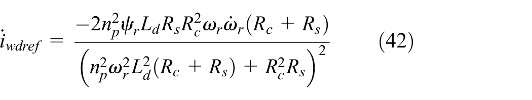
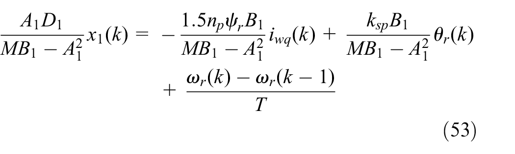
It can be seen from equation (32) that the active component of the d-axis current iwdref at a minimum electrical loss is

Backstepping controller design based on minimum electrical loss
Speed controller
Let eω = ωref – ωr, where ωref is the reference speed and eω is the variable depicting speed tracking error. Based on the principle of backstepping control, the derivative of eω can be obtained as

where
The virtual control variables iwqref are designed as follows
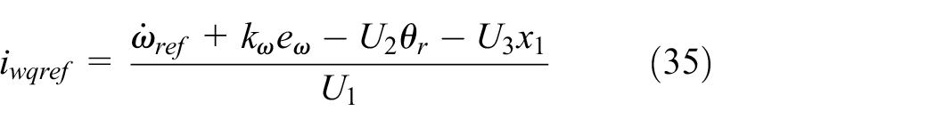
where kω is the speed control parameter greater than zero. Substituting equation (35) into equation (34) yields

Current controller
Let

Substituting the second expression in equations (29) and (35) into equation (37), equation (37) could be expanded as

According to equation (38), the first actual control variable uq is taken as follows
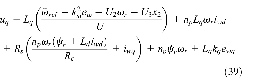
where kq is the q-axis current control parameter greater than zero.
Substituting equation (39) into equation (38) yields

Then let ewd = iwdref – iwd, where ewd is the error variable of the d-axis active current component. We can obtain the derivative of ewd as follows

The derivative of equation (33) can be obtained as
Substituting the first expression of equation (29) into equation (41) and performing some simplifications, we obtain
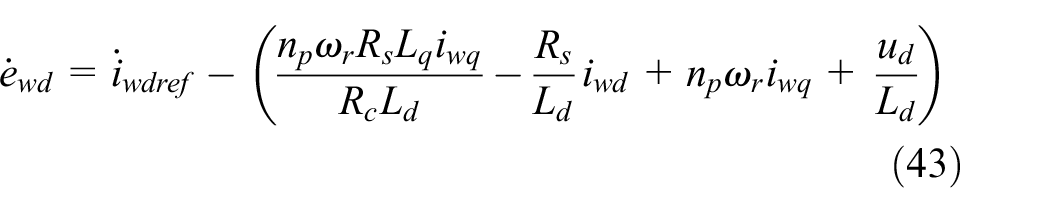
According to equation (43), the second actual control variable ud is obtained as follows

where kd is the d-axis current control parameter greater than zero.
Substituting equation (44) into equation (43), we can obtain

Proof of controller stability
The Lyapunov function Ly is selected as

The derivative of equation (46), and substituting equations (36), (40), and (45) into its derivative, the result is

Considering that Ly is bounded, based on equations (46) and (47), and in terms of Barbalat’s rule, when the time t approaches infinity, there is

This proves that the design of the backstepping controller is asymptotically stable. That is to say, under the action of the controllers ud and uq, the error system will gradually converge to the origin (0, 0, 0), and then the system state variables will also converge to their reference signals, respectively.
Identification of modal vibration of the spiral spring and iron loss resistance of the PMSM
Modal vibration identification of the spiral spring based on the least-squares algorithm
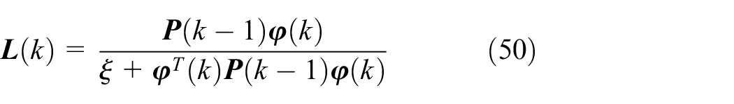
The least-squares algorithm is a commonly used identification algorithm in practice. Its basic principle is that when the identified system is running, each time new observation data are obtained, and the new observation data will be updated according to the recursive rule and the previous estimation. With the continuous introduction of new observation data, the parameters to be estimated are corrected until the parameter estimation reaches a satisfactory accuracy. As the identification program runs over time, more and more data will be collected. Especially for time-varying parameter systems, the identification results generated by new data are greatly affected by old data and may become inaccurate. The parameter to be identified in this article is just varying with time. In order to make the least-squares method have a good ability to identify time-varying parameters, the forgetting factor ξ (0 < ξ ≤ 1) is introduced on the basis of the general least-squares method, and the least-squares method with a forgetting factor is formed and shown as follows


where k is the sampling point,
In practice, the vibration mode η of the spiral spring is very difficult to measure. However, η as a state variable of the SSES system should be used in backstepping control. For this reason, this article completes the estimation of the vibration mode η through the least-squares method. When the identification model is to be estimated, the selected state equations should contain those parameters related to the vibration mode. Hence, the fourth expression of equation (29) is used as the state equation of the identification, the vibration mode η is chosen as the identification parameter, and the expression in terms of the format of the least-squares method is written as follows

Discretizing equation (52), we can obtain
where


where T is the sampling period.
By substituting equations (54)–(56) into equations (49)–(51), the vibration mode η of the spring can be identified.
Identification of iron loss resistance based on the ANFIS
To accurately identify iron loss resistance is of great significance for the PMSM system to pursue a minimum electrical loss and achieve optimal control. In order to realize the precise identification of iron loss resistance, this study tries to use an ANFIS.
The ANFIS fully integrates the neural network’s learning mechanism with a fuzzy system’s fuzzy rules. By learning from the training data, the membership function and fuzzy rules between input and output variables are autonomously selected and corrected. The structural principle is shown in Figure 3.

Structural schematic of the ANFIS.
The first layer is the fuzzy layer. This layer fuzzifies the input variables and outputs the membership degree of the corresponding fuzzy set. The input variables m1 and m2 correspond, respectively, to the fuzzy sets Ai and Bi (i = 1, 2).
The second layer is the fuzzy set operation. This layer multiplies the membership function of the input variable as the fitness ωi, where ωi = Ai(m1)·Bi(m2) (i = 1, 2).
The third layer is the normalized layer. This layer normalizes the fitness function. It is that
The fourth layer is the fuzzy rule operation. This layer is to calculate and output the rules of the fuzzy system, where
The fifth layer is the output layer. This layer calculates the output of the fuzzy system as the total output, which selects
Considering that if the training samples are obtained online and the ANFIS is trained online, it will take up a huge amount of memory and time, which is unsatisfactory for the fast response of the SSES system. Therefore, this article intends to use an offline training ANFIS to identify iron loss resistance online. The most critical part of the ANFIS is to obtain training samples. The following method is to describe how to obtain training samples.
When the PMSM operates at a stable speed, the corresponding iron loss resistance is constant. At this time, with the control of the closed-loop system, the output current of the speed controller is the actual q-axis active current component iwq_t. Assuming that Rc is a constant and is substituted into equation (3) together with the q-axis active current component iwq_t, the d-axis current component icd_f flowing through the iron loss resistor can be obtained. id could be measured. The d-axis current active component iwd that is the output current of the current controller is substituted into equation (3). The actual d-axis current component icd_t flowing through the iron loss resistor could be obtained. The current component icd_f is just calculated from the assumed iron loss resistance Rc.
Comparing the calculated current icd_f flowing through the iron loss resistor with the actual current icd_t flowing through the iron loss resistor, if icd_f is equal to icd_t by changing the iron loss resistance Rc, it will mean to successfully find the actual iron loss resistance Rc at this time corresponding to the operating state. For various stable operating states at different speeds, a certain amount of desired training samples corresponding to iron loss resistance can be gained through this method.
Implementation of the control method
In line with the above analysis, the implementation structure of the whole control method is shown in Figure 4, where the least-squares estimation of unknown vibration mode is completed by equations (54)–(56), and finally overall backstepping control scheme is proposed to realize minimum electrical loss control and speed regulation simultaneously, which includes three parts: minimum electrical loss controller (equation (33)), speed controller (equation (35)), and current controller (equations (39) and (44)).

Implementation of the control scheme.
Hardware experiment and result analysis
In order to verify the effectiveness of the proposed control scenario, a hardware experimental platform for driving the MEES system with the PMSM is designed as shown in Figure 5. The hardware experimental platform uses TMS320F28335 as a control chip, and the flexible spiral spring is installed in the spring box.

Hardware setup of the MEES system driven by the PMSM: (a) system composition diagram and (b) vibration mode monitor.
The parameters of the PMSM are as follows: stator winding phase resistance Rs = 2.875Ω, stator inductance Ld = 0.033 H, pole logarithm np = 50, and permanent magnet flux ψr = 0.3 Wb. The spiral spring is designed and manufactured based on the national standard JB/T 7366-1994 of China, and the parameters of the spring material are as follows: elastic modulus E = 2 × 10¹¹ N/m2, width b = 0.050 m, thickness h = 0.0018 m, length L = 14.639 m, torque coefficient c1 = 3.95 N m, and mass density ρ = 7850 kg/m3. According to equation (15), the first-order modal frequency of the spiral spring is f = 0.062 Hz. The forgetting factor ξ of the least-squares method is 0.94 and the control parameters in the backstepping controller are set to kω = 5, kq = 100, and kd = 10 through the trial and error method.
In order to testify the performance of the control algorithm and show its superiority better, the proposed control scheme is compared with the control algorithm without both vibration suppression and minimum electrical loss control (Algorithm I) as well as the control algorithm adding only vibration suppression (Algorithm II). The verification experiments are divided into three groups.
First experiment: low-speed steady-state test
The first experiment is to demonstrate the steady-state performance of speed tracking, vibration suppression, and minimum electrical loss control, respectively, by adding different controllers. The reference speed of the experimental motor is set to ωref = 2 rad/s, and the experimental time is 100 s. Figure 6(a) and (b) displays four currents with and without considering the operating efficiency of the PMSM, respectively, which are the q-axis active current component iwq, the q-axis current iq, the d-axis active current component iwd, and the d-axis current id. It can be obtained from equation (35) that, for a stable reference speed, iwq is mainly affected by the vibration mode of the spring and the rotation angle of the rotor. The experimental results show that the spring torque increases continuously during the energy storage process. When the reference speed of the rotor is 2 rad/s, iwq increases with the increase of the spring torque. If the operating efficiency of the PMSM is not considered, iwd will be finally controlled to zero reference accurately, which is consistent with the changing trend shown in Figure 6(a). However, equation (33) indicates that iwd is affected by the rotor speed with consideration of the operating efficiency of the PMSM. With the 2 rad/s reference speed, iwd is regulated as a nonzero constant. Equation (3) demonstrates that the d–q axis currents are consistent with the results shown in Figure 6(a) and (b). Figure 6(c) shows the comparison of the speed of the rotor with three control approaches. The comparative results show that if the vibration is not inhibited, the motor will run around the reference speed influenced by the vibration mode of the spring, and the system cannot store energy very ideally and stably. If vibration suppression control is applied, the rotational speed of the rotor can finally track the reference rotational speed. Figure 6(d) shows the variation of total electrical loss Ploss with and without applying to minimum electrical loss control, respectively. From equation (6), for a stable reference speed, Ploss is affected by iron loss resistance and iwq, and, whether or not the operating efficiency of the PMSM is controlled, the total loss of the system during the energy storage process varies with the increase of the spring’s torque. When the efficiency of the system is effectively controlled, the total electrical loss of the system is relatively reduced in contrast to no loss control, and thus energy storage with a higher efficiency is realized.
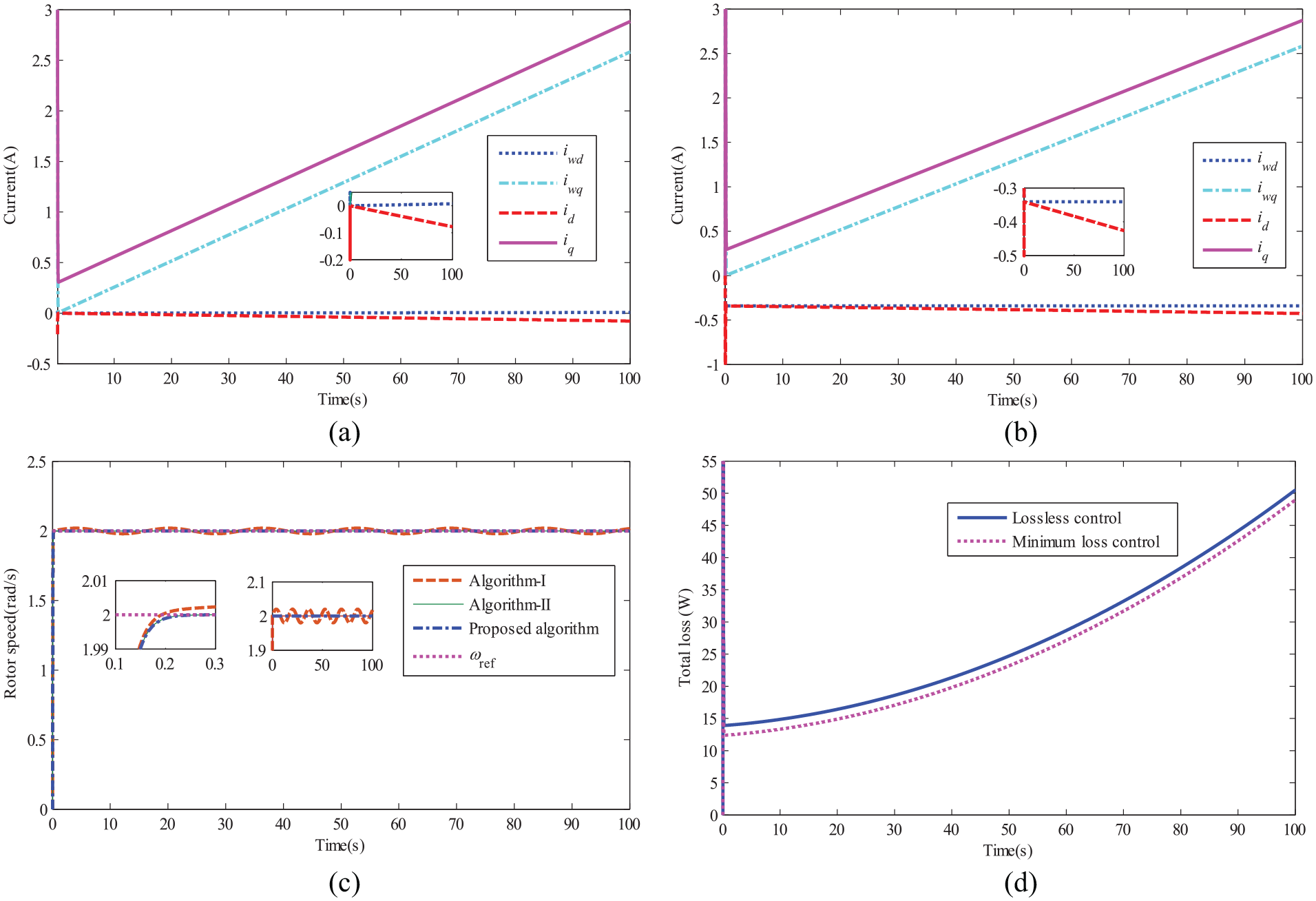
First experiment: low-speed steady-state experimental results: (a) currents without considering the operating efficiency of the PMSM; (b) currents considering the operating efficiency of the PMSM; (c) comparison of rotor speed for three different controls; and (d) comparison of total electrical losses with and without loss control.
Second experiment: dynamic test
The second experiment is to verify the dynamic performance of the control scheme and the rotor reference speed is dynamically changed. The reference speed of the rotor ωref is set to 2 rad/s from the standstill to 20 s, and the rotor reference speed is abruptly changed to 6 rad/s at 20 s. The rotor reference speed is abruptly changed to 2 rad/s in 60 s and lasts until the end of the experiment. The experimental duration is also set to 100 s. Figure 7(a) and (b) shows the currents with and without considering the operating efficiency of the PMSM, respectively. The experimental results show that the increasing rate of iwq remains basically the same when the rotor reference speed is 2 rad/s. Nevertheless, when the rotor reference speed changes to 6 rad/s, the increasing rate of iwq is much faster than that at 2 rad/s, and iwq ripples slightly when the rotor reference speed changes abruptly. It can be seen from equation (33) that, when considering the operating efficiency of the PMSM, iwd will be a different constant at a different rotor reference speed, and iwd will vary with changing reference velocity. Figure 7(c) shows the speed of the rotor when different control approaches are applied. The experimental results show that the motor still enables to achieve fast tracking of the reference speed even if the rotor’s reference speed changes abruptly. The tracking performance is also acceptable. Figure 7(d) shows the variation of total electrical loss Ploss of the system with time. For different rotor reference speeds, the total electrical loss of the motor expands as the torque of the spring increases during the whole energy storage process. Meanwhile, since iron loss resistance grows larger with the increase of the rotor reference speed, the increasing rate of Ploss remains basically unchanged with a fixed rotor reference speed of 2 rad/s. However, when the rotor reference speed is 6 rad/s, the increasing rate of Ploss is faster than that at 2 rad/s, and also Ploss changes with the rotor reference speed.

Second experiment: variable-speed dynamic experimental results: (a) currents without considering the operating efficiency of the PMSM; (b) currents considering the operating efficiency of the PMSM; (c) comparison of rotor speed for three different controls; and (d) comparison of total electrical losses with and without loss control.
Third experiment: high-speed steady-state test
The third experiment is a high-speed steady-state experiment with a 30 s experimental duration. The reference speed ωref of the rotor is set to 10 rad/s. The experimental results in Figure 8(a) and (b) show that iwq increases slightly faster with a 10 rad/s rotor reference speed during energy storage. In terms of equation (33), when considering the operating efficiency of the PMSM, iwd is smaller than that in the first experiment. Furthermore, it can be seen from equation (3) that the d-axis iron loss current component icd is negatively correlated with iwq, and the q-axis iron loss current component icq is positively correlated with iwd. The d-axis current is composed of the active component iwd and the iron loss component icd. The q-axis current is also composed of the active component iwq and the iron loss component icq, and its trend curve is consistent with the theoretical value. Figure 8(c) shows the results of the rotor speed with three control algorithms. The experimental results show that although the rotor reference speed becomes larger, the PMSM can still achieve fast tracking of the reference speed. Especially, the introduction of vibration suppression gives better control performance. Figure 8(d) presents the variation of the total electrical loss Ploss with time. Since iron loss resistance grows with the increase in rotor reference speed, in comparison with the first experiment, Ploss at 10 rad/s rotor reference speed increases faster and results in a larger value.
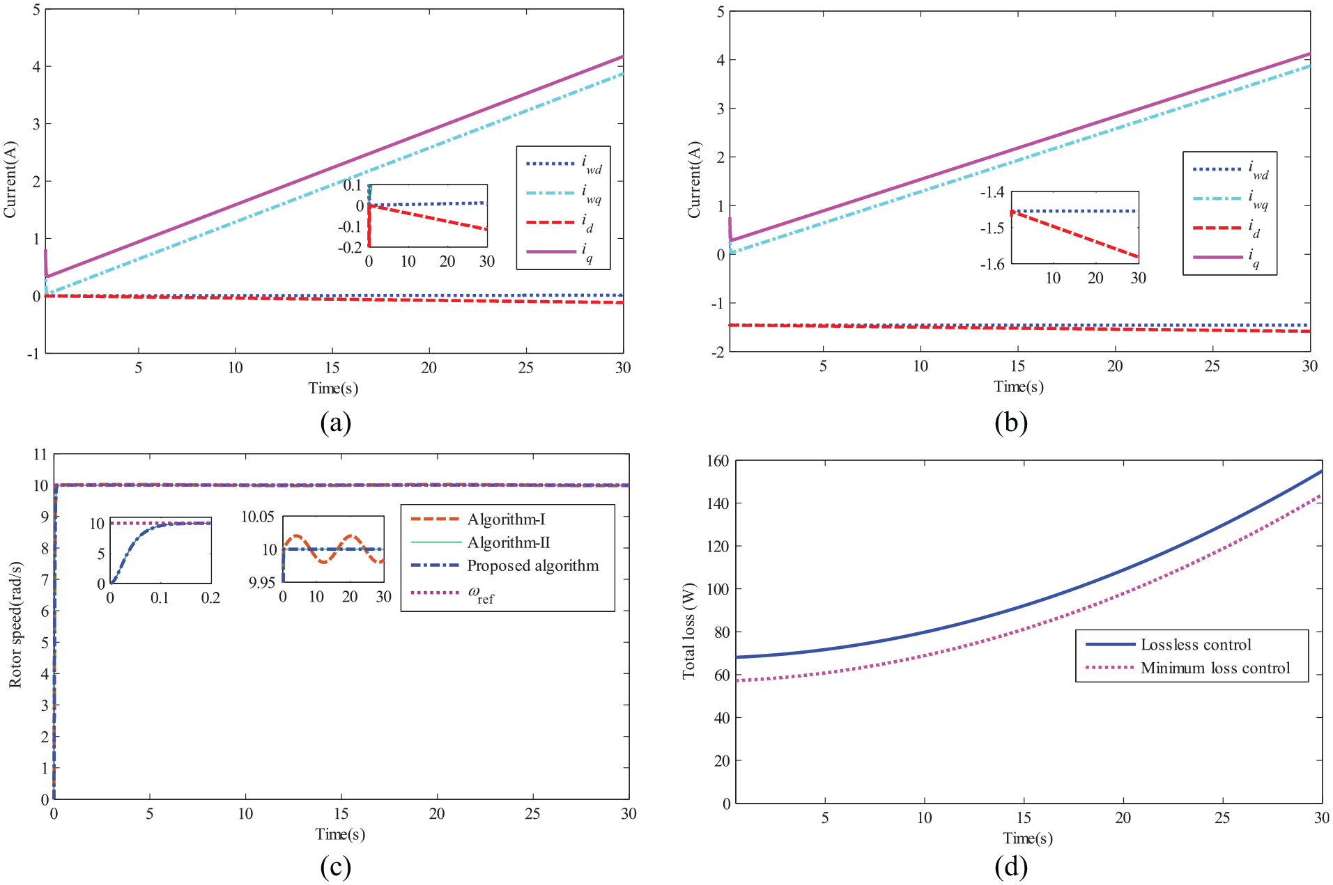
Third experiment: high-speed steady-state experimental results: (a) currents without considering the operating efficiency of the PMSM; (b) currents considering the operating efficiency of the PMSM; (c) comparison of rotor speeds for three different controls; and (d) comparison of total electrical losses with and without loss control.
In addition, equation (14) indicates that the vibration mode of the spring could be represented by a sinusoidal function. The vibration mode of the spring in the first experiment that is measured by the hardware experimental platform shown in Figure 5(b) is contrasted with the estimated value using the least-squares method, and the result is shown in Figure 9. It means that the estimation of the spring mode obtained by the least-squares method is basically consistent with its actual vibration mode.

Comparison of the estimated vibration mode with its actual value for the spring.
Conclusion
In this article, to address the issues of vibration control, speed regulation, and minimal control for the SSES system driven by the PMSM simultaneously, an integrated control scheme of backstepping control, least-squares modal estimation, and ANFIS identification of iron loss resistance is developed. The results of the study are as follows:
When the system is subjected to vibration suppression control and minimum electrical loss control, it is able to achieve stable and efficient energy storage, and the feasibility and effectiveness of the proposed algorithm are verified.
The proposed control method can guarantee the state variables to track their reference signals precisely and rapidly, and the dynamic performance of the control scheme is good.
The least-squares estimation algorithm enables to accurately identify the vibration mode of the spring, and the iron loss resistance is correctly identified by the ANFIS.
Although the backstepping control algorithm proposed in this article has achieved a good control effect, it still has some application limitations, mainly reflected in the relatively large calculation amount of backstepping control. Backstepping control is a kind of nonlinear control. Because the design process of the controller involves the differential calculation of the virtual control variables, which makes the actual controller expression relatively complicated, the problem of “calculation explosion” may be encountered. In the next step, it is possible to combine backstepping control with sliding mode control or some other control approaches to reduce the computational overhead and achieve a faster algorithm. In addition, the energy storage system in this article uses an AC/DC/AC converter to convert the energy between the power grid and the PMSM. In this article, only various electrical losses are considered. In the future, the converter loss and the mechanical loss in the energy storage system could be optimized and controlled.
Footnotes
Handling Editor: James Baldwin
Declaration of conflicting interests
The author(s) declared no potential conflicts of interest with respect to the research, authorship, and/or publication of this article.
Funding
The author(s) disclosed receipt of the following financial support for the research, authorship, and/or publication of this article: This work was supported in part by the Natural Science Foundation of Hebei Province in China (Grant No. E2019502163), the Fundamental Research Funds for the Central Universities (Grant No. 2017MS095), in part by “Double-First Class” Scientific Research Project in School of Electrical and Electronic Engineering of North China Electric Power University (Grant No. 180718), and in part by the Headquarter of Science and Technology Project for Sate Grid Corporation of China (Grant No. KJGW 2018-014).