
Abstract
The exact understanding of the dynamic characteristic of the seal is a crucial parameter for designing the system. This article presents an experiment that estimates the dynamic characteristics of a brush seal under a super-heated steam environment for a steam turbine. The super-heated steam facility makes super-heated steam (523.15 K) to replicate the real steam turbine environment. Two brush seal units are utilized with a housing connected by springs to measure the modal parameters of the system. To extract the brush seal characteristics, the modal parameters of the pure housing were subtracted from the overall dynamic system. Moreover, to predict modal parameters more accurately, the least-squares method and the instrumental variable method were used to reduce the noise caused by the steam. Two major effects were experimentally investigated by varying the operating speed (0–16,900 r/min) of the rotor and the injection flow of super-heated steam. The results showed that the direct stiffness and damping of the brush seal increased significantly when the steam was injected. Under steam exposure, obtaining the modal parameters using instrumental variable method was confirmed to reduce more noise than obtaining the parameters via least-squares method.
Introduction
A rotating seal is widely used in many rotordynamic applications, 1 for many reasons. Sealing is of prime concern, especially for power generation, since the leakage of working fluid negatively affects the on-power efficiency. In general, labyrinth seals were used, since their teeth serve as fluid blocking walls, resulting in improved sealing performance. 2 Labyrinth seals have been thoroughly researched.2,3 El-Gamal et al. 2 estimated the labyrinth seal performance according to the geometry of labyrinth based on the continuity and momentum equation. In the up-the-step seal, the rotational speed had a good effect on labyrinth performance, but it was found to have an adverse effect on the performance of the grooved shaft and casing cases. Subramanian et al. 3 analyze the rotordynamic characteristics of labyrinth seal considering centrifugal growth effect using numerical analysis method. There was a significant change in cross-coupled stiffness and direct damping coefficient of the labyrinth seal, especially when the pressure ratio was low. So, the dynamic characteristics of the labyrinth seal under various boundary conditions were more accurately predicted. However, it is nearly impossible to achieve zero clearance for labyrinth seals due to its structural limit. Also, the clearance itself can be a source of fluid-induced instability such as steam whirl at high rotational speed, which is necessarily avoided. 4
Developed early for gas turbines in aircraft,5,6 brush seal usage has been extended to the industrial gas turbines, steam turbines, 7 and even some extreme situations, such as cryogenic and lunar applications.8,9 However, care should be taken since physical complexities, such as canted angle, bent bristles, and splicing effect of bristles, 10 make brush seals more challenging to analyze than conventional labyrinth seals. 11 For commercial steam turbines, the existence of flexible bristles can cause poor sealing performance.
To overcome the abrasive nature and undesired structural effect of bristles, novel materials have been studied.12,13 However, Haynes 25 is still preferred for steam turbine brush seals where high temperature tolerance and resilient bristles are needed. 14 Heat generation effects arising from friction were investigated numerically 15 and experimentally, suggesting a theoretical heat generation model. 16
To unveil the unknown dynamic characteristics of brush seals, numerous studies on various aspects of brush seals have been conducted. As suggested by Nordmann and Massmann,17,18 the dynamic characteristics of triboelements have been utilized to analyze a given rotordynamic system.19–23 In particular, additional stiffness or damping could be the source of destabilizing force, inducing the steam whirl. 4 In addition, thermal instability, such as the Newkirk effect, can appear due to unavoidable frictional heating resulting from contact between the bristles and rotor. Therefore, experimentally investigating the dynamic characteristics of brush seal embedded systems is paramount to ensuring reliable operation. Conner and Child 19 experimentally investigated the dynamic coefficients of a four-row brush seal by changing inlet pressure, pressure ratios, and rotational speeds, and compared the results with the dynamic characteristics of the labyrinth seal. Their experimental results showed that the brush seal exhibited a higher dynamic coefficient than the conventional labyrinth seal, and the system stability was improved. Furthermore, the experimental results confirmed that the above-mentioned test conditions did not affect the dynamic characteristics of the brush seal. Pugachev and colleagues21,22 extracted the dynamic characteristics of a hybrid seal, combining the brush and labyrinth seals, by varying the arrangement of the location of the brush seal using experimental and theoretical methods. Also, the experimental and theoretical methods estimated the blow-down effect of stiffening of the bristle pack versus the pressure differential. The stiffness of the brush seal was extracted through the circumferential pressure distribution between the bristle packs, and owing to the blow-down effect, the dynamic characteristics of the brush seal depend largely on the eccentricity of the shaft. Raben et al. 23 successfully analyzed chronological wear development of the clamped brush seal and investigated blow-down effect and bristle stiffness under super-heated steam environment. The low inclined bristle of the tandem geometry presented a continuously increasing wear to the rotor and bristle tip surface and showed the performance influenced by the bristle pack design. However, Raben’s research could not explain the dynamics of rotating brush seals, especially under super-heated steam conditions.
In this study, the experimental rotordynamic characteristics of brush seals were studied in depth. The dynamic coefficients of the brush seal were extracted assuming 2-degrees-of-freedom (2-DOF) linear system in a super-heated steam environment that has a high kinetic energy. The modal parameters of the brush seal were investigated using the least-squares method (LSM) and instrumental variable method (IVM), respectively, considering the noise effect of the steam. In addition, the influence of super-heated steam under rotation and irregular clearance between brush seal and rotor was discussed.
Test apparatus and overall experimental procedure
Configuration of the brush seal for dynamic characteristics
Two major types of brush seals exist in the commercial brush seal industry, the clamped type, where the bristles are held with a clamping device, 24 and the welded type, wherein the bristles are connected via welding. Although the absence of the welding procedure gives some advantages, the clamping type introduces additional design complexity called axial inclination angle. The inclination angle is analyzed in detail in the work by Schwarz et al. 25 Figure 1 depicts the test brush seal, which consists of four segments and is welded type. Table 1 lists the detailed information on its configuration. In addition, Figure 2 shows that the number of bristles per area was calculated to obtain the exact porosity (18%).
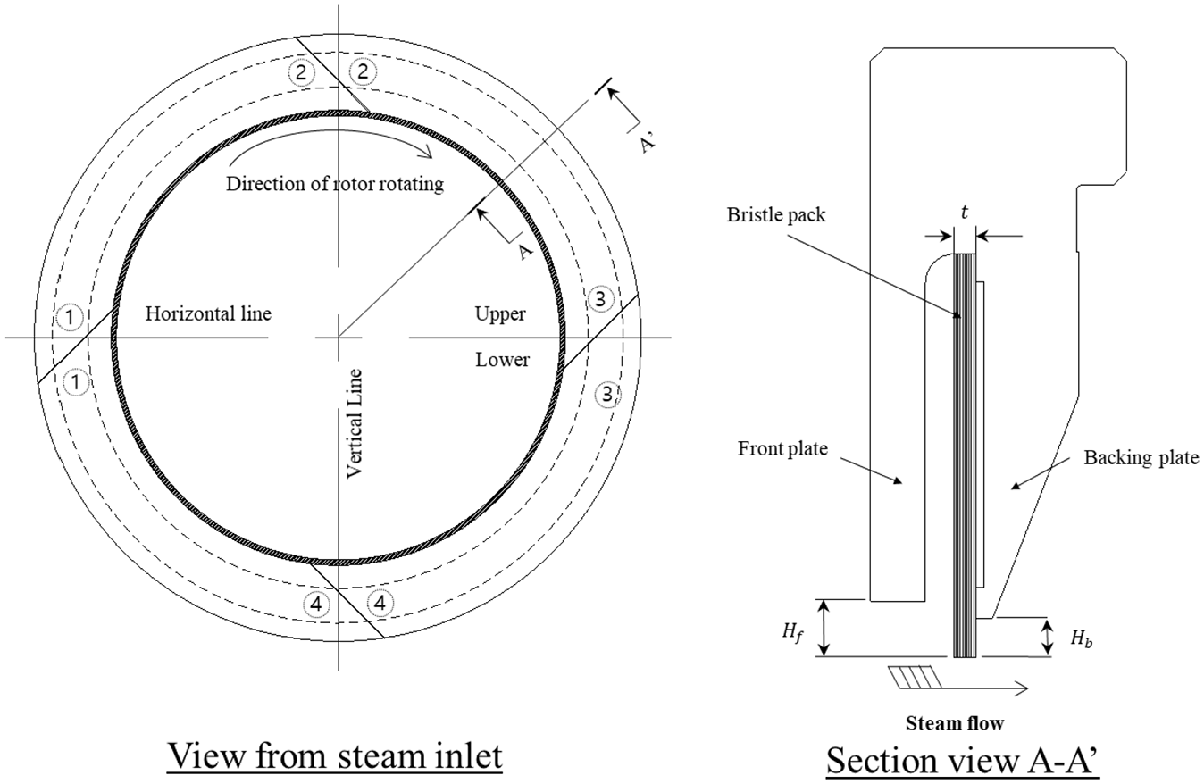
Configuration of test brush seal for dynamic characteristics.
Geometry information of the test brush seal.

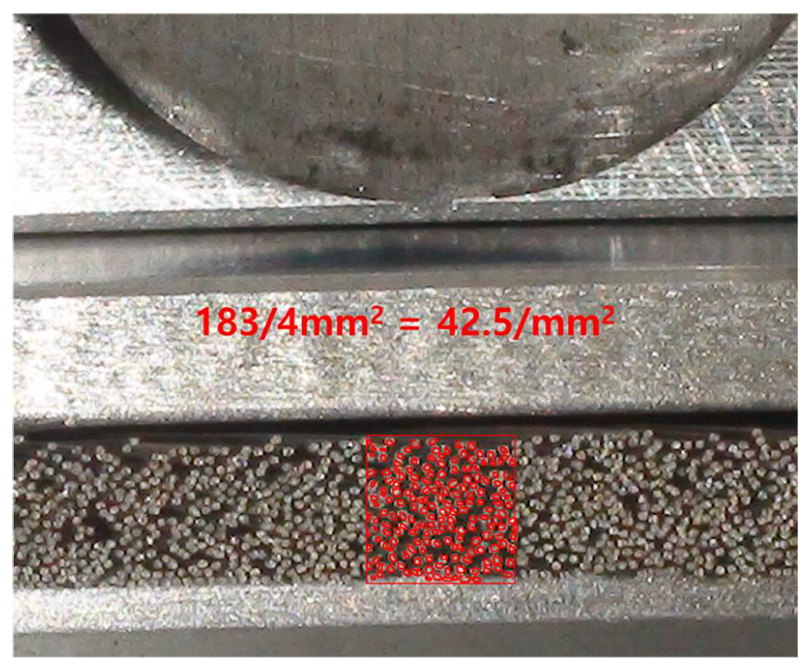
Measurement of the porosity of test brush seal for dynamic characteristic.
Experimental setup for dynamic characteristics under super-heated steam
Figure 3 illustrates the overall system view for the dynamic characteristics of the brush seal. The steam generator produces steam with a pressure up to 10 bar. Pressurized steam directly enters the super-heater, which increases the steam temperature to 250°C, obtaining super-heated steam. A flowmeter is installed where the outlet steam exits the housing, to measure the sealing performance of the seal and to monitor the abnormal behavior of the steam flow. Note that the mass flowmeter was experimentally calibrated, since the flowmeter cannot predict the steam flow properly. Finally, two electro-magnetic shakers, which were amplified by the voltage amplifier, were utilized to excite various dynamic forces generated by the function generator.
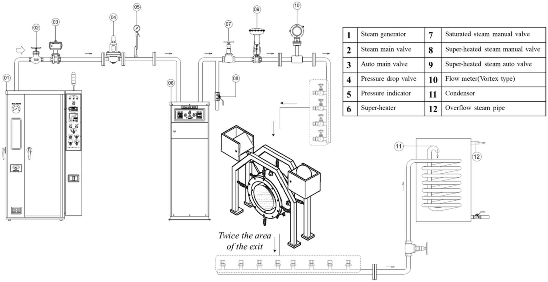
Overall schematic view of the apparatus setup for determining dynamic characteristic of the brush seal under super-heated steam.
Figure 4 shows a detailed schematic of the test bench. The bench is mainly composed of two parts: a driving motor and a rotor-housing assembly. The driving motor rotates a rotor connected via flexible coupling where the rotor makes a contact with test brush seals. Rotating speed is monitored with a tachometer, reading the tip speed of the rotor. Two angular contact ball bearings lubricated with oil support the rotor, since they operate stably from 0 to 16,900 r/min. Weak flexible coupling mode was observed, but the mode was sufficiently negligible. In Figure 5(a), a housing, including two brush seal units, is located in the middle of the rotor. Although the housing is equipped close to the rotating disk, it is only supported by springs vertically and horizontally, ensuring the precise dynamic response of the brush seal. Figure 5(b) shows where the four displacement sensors are installed in the housing; two (X and Y) on the left side of the housing and two on the right.

Layout of test apparatus for dynamic coefficients of brush seal. 26

Extracting dynamic coefficients of brush seal: (a) overview of 2-DOF test apparatus and (b) force and displacement sensor spot.
They measure the frequency response during excitation and the vibrational level of the rotor. Nyquist plots are obtained from both sides with an oscilloscope. A force sensor is individually applied in the X and Y directions, which computes dynamic excitation forces. The sensors are connected to a fast Fourier transform (FFT) analyzer, which records input data in the time and frequency domains. In addition, temperature and pressure sensors are installed on the housing at the inlet and outlet sides. Similarly, the sensors are connected to a data acquisition (DAQ) device to monitor the conditions of super-heated steam during the experiment. Inlet/outlet temperature and pressure of brush seal were monitored with DAQ device and LabView software from National Instruments. To obtain dynamic characteristics, the frequency response function (FRF) of a given dynamic system ought to be analyzed. Therefore, displacement and force sensors are connected to the FFT analyzer called PULSE from B&K. The external force was applied utilizing electromagnetic shakers. White noise was used to investigate the effect of a broad frequency range. Once the signal excites the shaker, a stinger directly connected to the force sensor shakes the housing. Note that the housing is connected to multiple hoses to inject the steam. Therefore, the effect of the hoses can critically affect the excitation result. In the experiment, flexible hoses are employed, minimizing the additional interference. In addition, a static load with respect to the vertical direction is applied to balance the gravity force of the housing. Once the signal is measured, excited forces and displacements are converted to the Fourier transformed signals by an FFT analyzer to calculate FRFs. Transformed signals are post-processed to transfer functions. Table 2 shows the experimental operating conditions. The frequency results were recorded from 0 to 400 Hz, which includes the maximum rotation (
Operating conditions of the brush seal for dynamic characteristic.

Investigating friction effect of the rotor surface
The friction effect was checked to remove the external elements affecting the experiment. Due to the existence of an interface between the existence of bristles and the rotor surface, heat may be generated owing to friction. 14 Considering the friction, rotation experiment with 16,900 r/min without working fluid was conducted. The operation was continued until the steady state was obtained. The surface temperature was monitored by an infrared camera that exports temperature with respect to time. As shown in Figure 6, the temperature reaches a steady-state value of 50°C. This is much less than the value obtained from the work by Ruggiero et al., 13 considering approximately three times higher sliding velocity (265.5 m/s). Therefore, the interface of the current brush seal installation can be expected to be small, which negligibly increases the temperature over the operating temperature (maximum 250°C). The saturated liquid diagram of the steam (Figure 7) was used to confirm that the working fluid used in this experiment maintained the state of the super-heated steam during the experiment. These processes checked the properties of the working fluid and reduced the experimental error caused by the thermal expansion.

Surface temperature without steam (left) and infrared camera image (right).

Temperature versus enthalpy of working fluid to check the status.
Method for extracting the modal parameters of the brush seal
Although one-dimensional analysis offers simple and intuitive results, it is nearly impossible to explain destabilizing forces with direct stiffness and direct damping coefficients alone. Therefore, we assume a 2-DOF dynamic system, which enables analyzing the cross-coupled terms in this article and the two-dimensional (2D) governing equations are

in frequency domain

by definition of receptance and applying Fourier transform in equation (2)


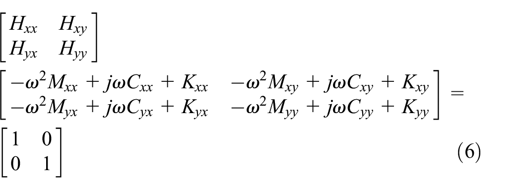

Equation (7) can be expressed as follows
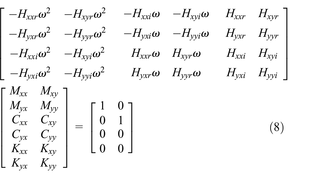

However, the expanded matrix form is underdetermined, making the given system of equations unsolvable. Approximating modal parameters by least squares, a given system becomes overdetermined. Solving normal equations applied by pseudoinverse, the experimental values of the modal parameters are calculated as follows

Figure 8 presents a flowchart of the overall LSM process. In addition to LSM, IVM was used for the experimental analysis. The main difference between LSM and IVM is that IVM includes an additional iterative scheme for approximating dynamic parameters. IVM is well known to better fit curves resulting from noisy signals. 26 Therefore, IVM is expected to mitigate the noise induced by the steam environment. LSM and IVM are formulated in detail in the previous studies.17,18,27
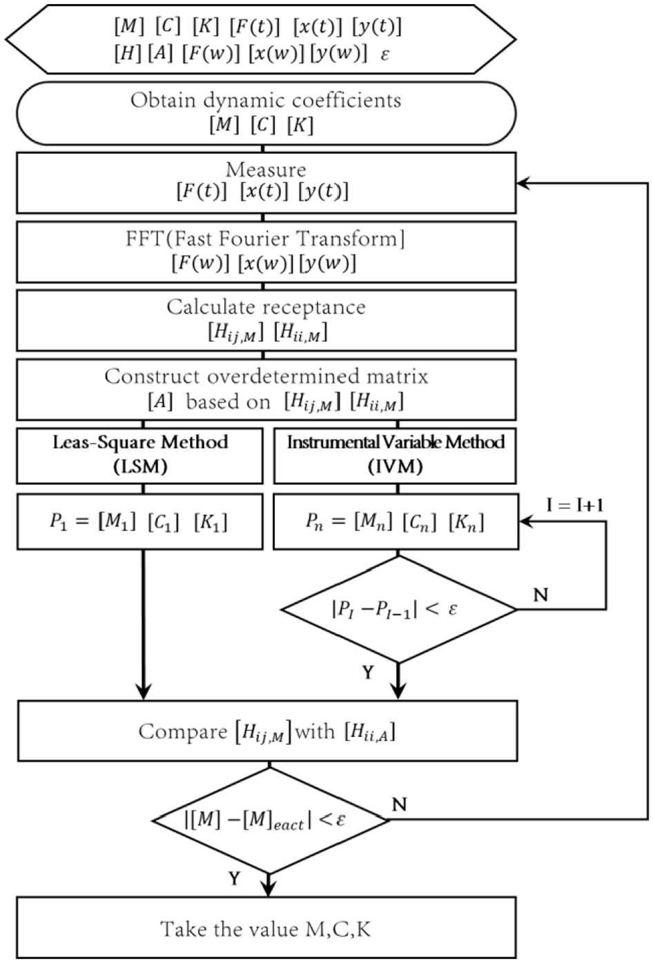
Flowchart for extracting the dynamic coefficient of the brush seal. 27
Experimental results and discussion of the modal parameters for the brush seal under super-heated steam
Estimating the irregular clearance between the rotor and brush seal
The brush seals are designed for zero clearance. However, several factors are unavoidable in real operation, such as manufacturing tolerance, shaft excursion, vibration of the housing, and improperly installed brush seal units. Moreover, the interface should be verified to analyze the friction effects.
Thus, installation clearances are measured utilizing a three-dimensional (3D) non-contact coordinate measuring machine. A dummy rotor with the same dimensions except for the length was used because the length of the real rotor did not fit in the measuring machine. The clearance points were measured at each 10° angle. Figure 9 reveals a wide-clearance range, which is a clear indication of irregularity.
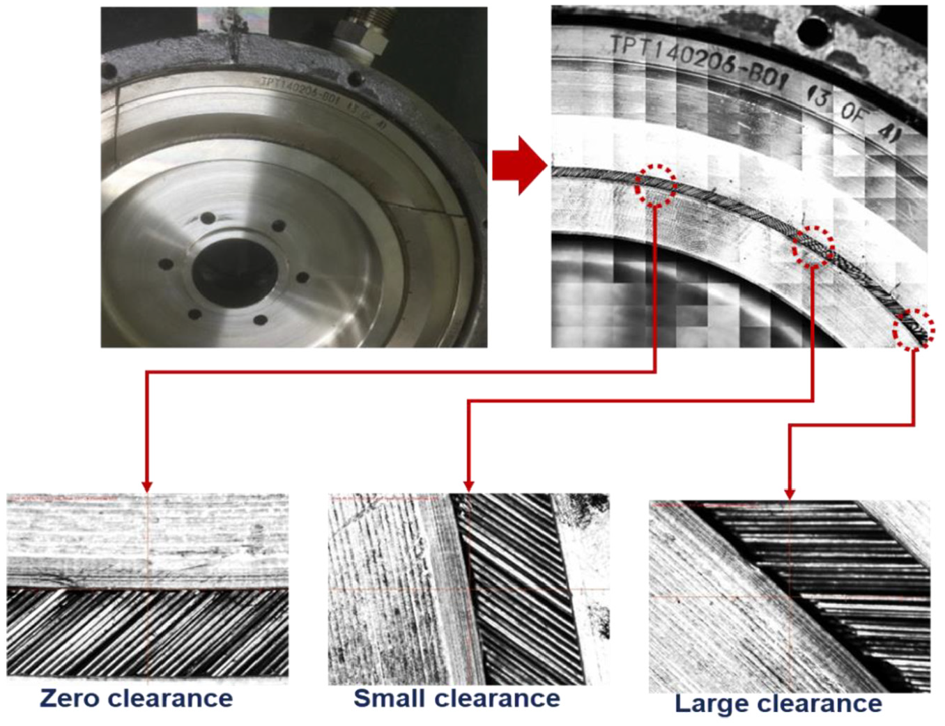
Estimation of the irregular clearance of the brush seal via non-contact 3D coordinate measuring machine.
In particular, negative clearance points (in other words, interfaces) were measured in a certain region. Such irregularities cause not only friction but also dynamic characteristics, since the clearance can easily affect the motion of bristles. The dynamic characteristics are further discussed in the next section.
Analyzing the FRF for the brush seal
To analyze the dynamic brush seal effect, the dynamic coefficients of the housing must first be extracted. Thus, the FRF of the housing (without brush seal) was measured. LSM and IVM fit the experimental data and precisely approximated the real mass. Note that superscript E, L, and M represent the experimental value, LSM, and IVM, respectively. A resonance peak appeared at low frequency (9 Hz). Next, FRF of the brush seal equipped housing with various rotating speeds (0; 6000; 12,000; and 16,900 r/min) was obtained. Figure 10 denotes direct FRF with two rotating conditions (static and 16,900 r/min). Also note that FRF with super-heated steam was obtained (superscript “st,” indicated by red lines).

Direct frequency response: 0 r/min (top) and 16,900 r/min (bottom). Superscripts—E: experimental; L: least squares; I: instrumental variables; and st: steam injected.
Regardless of rotation, the resonance frequency was low (9–10 Hz). According to the plots, IVM and LSM both showed reasonable fitting capabilities. However, the housing mass calculated via IVM was more accurate. In addition, LSM exhibited poor fitting performance for several cases, especially for steam experiments, because the additional iterative scheme of IVM leads to robust fitting even with noisy signal due to the steam.
Therefore, choosing IVM is preferred for the steam experiments. A lower peak appeared with brush seals when the rotor was static. The peak shifts considerably as the rotation begins. Figure 11 shows that the resonance peak tends to increase as rotating speed increases.

Effect of rotating speed without steam (top) and with steam (bottom). Superscript—kr/min (rotating speed).
This implies that the brush seal plays an important role as a damper of the system. When the rotor is static, bristles make contact to the rotor disk with static friction force. Once the rotor rotates, kinetic friction force lowers the interaction between bristles and the disk surface. In other words, alleviated bristle friction forces stemming from bristle–bristle, bristle–back plate, and bristle–shaft contacts result in higher peak with rotation.
Another notable result is asymmetric peaks depending on directions. Figure 11 implies that a resonance peak with a higher value was obtained in the Y direction, although the peaks without a seal were almost same, which can be explained by the irregular clearance in the static condition and additional eccentricity resulting from whirling effect of the rotor when it rotates. As shown in the previous section, irregular clearance is formed in the brush seals. Therefore, different clearance values allow the asymmetric peak in the static condition. As rotating speed increases, whirling motion also increases, leading to more irregularity of clearance points. For example, the clearance with an interface will have a higher interface, and large clearance points will have larger clearance during rotation, suggesting that the interface is majorly formed in the Y direction.
Under a super-heated steam environment, several changes were observed. First, the resonance peak decreased overall, which means the steam acts as a damper. In addition, centrifugal expansion of the disk and thermal expansion enhance the interface, allowing more friction force. Second, the resonance peak is shifted slightly (9 Hz → 10 Hz), implying that the steam changed the given rotordynamic system. The reason is closely related to the steam flow. Since the added mass effect of the steam was smaller than the stiffness increase, the resonance frequency tended to increase.
Modal parameters of the brush seal under super-heated steam
Figure 12 depicts the dynamic characteristics of the brush seal. Without the steam, relatively low dynamic values were discovered, and

Cross-coupled and direct frequency responses: 0 r/min (top) and 16,900 r/min (bottom).
The reason is that the higher whirling amplitude resulted in more interaction between bristles and the disk surface. The interaction plays a major role as an additional spring and a damper. In the super-heated steam environment, the overall values of coefficients increased, which can be explained by two factors.
First, high temperature and interaction with hot gas stiffened the bristles. Second, the steam flow worked as additional spring and damper in parallel. Once the rotor rotates faster, increased whirling amplitude squeezes out the steam inside the housing. Therefore, the decreasing tendency of coefficients became more distinct with higher rotating speeds. Specifically, additional dynamic characteristics can be explained by the blow-down mechanism. Since the bristles are flexible, they are very responsive to radial forces. As the steam is injected vertically, bristles easily go downward causing stiffer bristles structurally. Different from the direct coefficients, no clear tendency was observed for cross-coupled terms. Notably, two negative values appear,
Uncertainty analysis
Assuming experimentally derived variable W with dependency of

where W =
Uncertainty of the dynamic coefficients of the brush seal.

Conclusion
Herein, experiments have been conducted to determine the dynamic characteristics of the brush seal applied to a steam turbine. To describe the real steam turbine environment, experiments were performed under super-heated steam, and the circumference velocity was identical to that of the actual steam turbine. LSM and IVM were used to extract the modal parameters of the brush seal. Also, to increase the experimental accuracy, the irregular clearance between the rotor and the brush seal was measured. In addition, the friction effect was checked. Here, we summarize the useful outcomes:
Surface friction heating due to the bristle interface was negligible (49.2°C), considering the relatively high sliding speed (265.5 m/s) and temperature of the steam (250°C). The steady-state temperature was much less than the value in the work by Kirk et al. 14
Compared to the static condition, rotation reduces the damping effect mainly because of static friction from multiple sources: bristle–bristle, bristle–disk surface, and bristle–back plate. The contact between the bristles and rotor disk and the blow-down effect originated from steam flow acting as an additional damper and spring. Due to the whirling of the rotor and irregular clearances, striking directional dependency was observed.
As rotating speed increases, the coefficients tend to decrease overall in a super-heated environment. Asymmetry also becomes more distinctive. The physical reason that the negative cross-coupled stiffness acts as a destabilizing force in the static condition requires further analysis.
When exposed to the steam, IVM showed better fitting capability that accord with the previous research. 27 Super-heated steam affected the rotordynamic system by means of bristles stiffening and flow-induced damping. Hence, examining super-heated steam effects is strongly recommended for research and rotordynamic design, not only to avoid catastrophic failure of the steam turbine but also to predict more realistic results.
Footnotes
Appendix 1
Handling Editor: Gang Xiao
Declaration of conflicting interests
The author(s) declared no potential conflicts of interest with respect to the research, authorship, and/or publication of this article.
Funding
The author(s) disclosed receipt of the following financial support for the research, authorship, and/or publication of this article: This material is based on research projects (“Improved Reliability of Ball Bearing for Extreme Environment and Developing Smart Ball Bearing Core Technology” NRF-2017R1A2A1A17069515) supported by the National Research Foundation of Korea, which is funded by the Ministry of Science, ICT, and Future Planning, Korea. The authors would like to thank for their contribution to this study.