
Abstract
In order to overcome the great interference of many ancillary facilities in the process of tunnel lining detection, a vehicle-borne high-speed railway tunnel lining detection device was designed based on the arc rotation mechanism to improve the detection efficiency and quality. The device could automatically maintain the antenna–lining distance and carry three radar antennas at one time, which detected the tunnel from the side of the catenary frame without stopping. Through the establishment of the mechanism three-dimensional finite element model, the simulation and analysis of natural frequency and vibration characteristics were carried out, and the results were confirmed by the field dynamic test. It is concluded that the dynamic characteristics can meet the technical requirements under the radial and the longitudinal vibration at 5 km h−1, but the detection data quality of the three radar antennas under the radial vibration is quite different. After optimizing the bent arm material to carbon fiber, the dynamic stability of the mechanism is significantly improved through simulation analysis and the detection speed can be increased to 10 km h−1 with a substantial leap.
Keywords
Introduction
With the construction and operation of high-speed railway and municipal subway, China has achieved rapid progress in hydraulic tunnel, municipal tunnel, railway tunnel, and underground engineering, which has made China one of the countries with the fastest development, the largest number, and the most complex technical conditions of tunnel engineering in the world. 1 However, due to the complex and changeable nature and topographic conditions in China, and the influence of various unfavorable factors in the design, construction management, operation, and maintenance of tunnels, there are various degrees of defects in tunnels, which seriously threaten the safety of train driving in tunnels.2,3 In order to ensure the safety of tunnel operation, effective measures should be taken to discover the defects to provide the basis for maintenance. The tunnel inspection mainly includes the lining surface inspection and the lining internal inspection. The three-dimensional (3D) ground laser scanning method, namely, three-dimensional terrestrial laser scanning (3DTLS),4–6 is used to detect the cracks, water leakage, and falling blocks on the lining surface. Generally, the ground-penetrating radar (GPR) method is mostly used to detect the cavity, uncompacted, water bearing, and other defects in the lining internal in China and other countries.7–9 Compared with the traditional manual detection method and some common geophysical methods, the GPR method has the advantages of being fast, efficient, nondestructive, continuous, and high resolution, and vehicle-borne detection is the development trend. In view of the GPR antenna fundamental, it is necessary that the antenna should be carried by the large support device to complete the detection operation. As a mobile platform of the supporting device, the key to improve the detection efficiency is to determine whether the detection vehicle can run fast without stopping. At present, there is no precedent for the mature application of detection devices in China’s high-speed railway tunnels.
According to the measured high-speed railway tunnel lining thickness and the defects’ depth range, the air-coupled multi-channel GPR (with center frequencies of 400 and 900 MHz, transmitting and receiving antennas integrated) produced by IDS Company was selected. The number of sampling points is 512/scan and the noncontact detection interval is 150 ± 50 mm. The detection depth is 0.7 m/1.5 m.
For the lining detection, the GPR antenna should be lifted to 10 cm of the lining surface, and the obstacles of the catenary should be avoided in time and effectively during the detection. These requirements can only be achieved with the support of a large-scale operating organization. The traditional detection device is usually a long straight-line telescopic mechanical arm, which is in the out-of-gauge state. The dynamic influence will be brought by the detection vehicle running process and the detection supporting device automatic adjustment, which produces the corresponding vibration characteristics, reduces the system’s dynamic stability, increases the controlling difficulty, and influences the quality of data acquired by the radar antenna. The viscoelastic damping materials are mainly used to control the vibration, which could achieve the purpose of restraining vibration by reducing vibration energy.10–18 Constrained damping layer structure consumes more vibration energy, which has been widely used in the engineering field. 19 However, additional structures should be added if it is necessary to adjust the natural frequency and vibration amplitude–frequency characteristics of the detection device, or the material properties such as the composite new materials should be changed.20,21 Therefore, this article focuses on the vibration characteristics of the detection device, including simulation calculation, in-plant dynamic test, and analysis.
Design of the tunnel lining detection device
China’s high-speed railway tunnels mainly have two cross-section forms corresponding to different speed grades, of which 350 km h−1 speed grade high-speed railway tunnels account for a larger proportion. The physical image is shown in Figure 1.
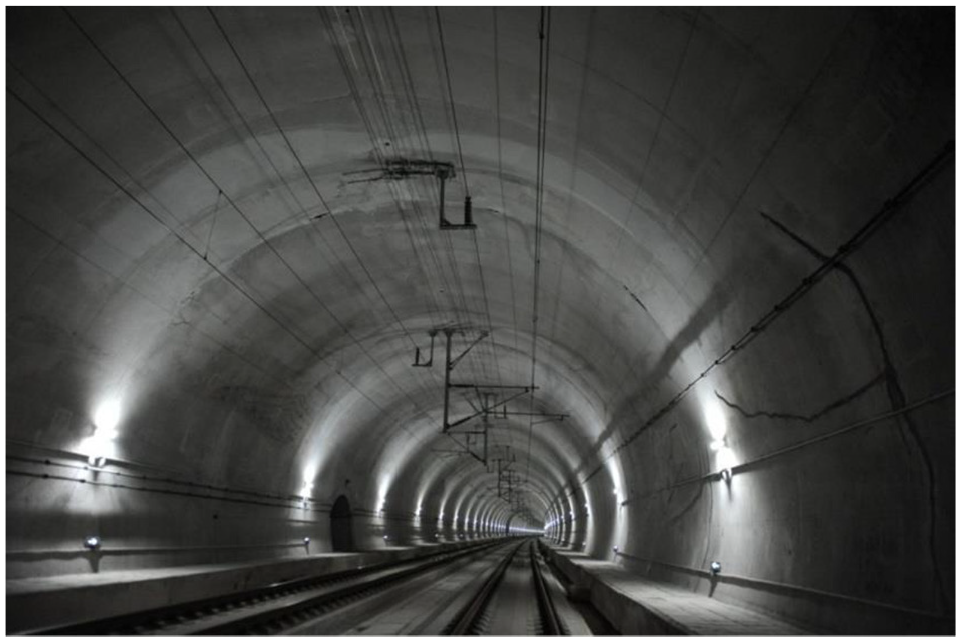
Field picture of the high-speed railway tunnel (speed grade = 350 km h−1).
The traditional large-scale mechanical arm has a long telescopic stroke and it is extremely difficult to achieve timely and effective evasion action when detecting high-speed railway tunnel arch waist and arch crown in the face of the long catenary frame.
In order to ensure that all the antennas can reach the designated height during the detection, a lifting platform is set up in the vehicle device warehouse. The platform weighs up to 3 t and the maximum lifting stroke is 1.2 m. The platform is operated by two hydro-cylinders. During the detection process, the platform is stationary and guide pillars are installed to ensure the positioning accuracy and stability.
The lifting platform is equipped with a mechanical arm, which is composed of a swinging telescopic mechanism (referred to as “main arm”) and a three-section arc rotating mechanism (referred to as “bent arm”). The mechanical arm can skillfully cross the catenary frame (periodically 30–50 m, or even more intensive) and pass through the side area without stopping, which carries out continuous detection according to the curvature of the tunnel lining contour. The design scheme is presented in Figures 2 and 3.
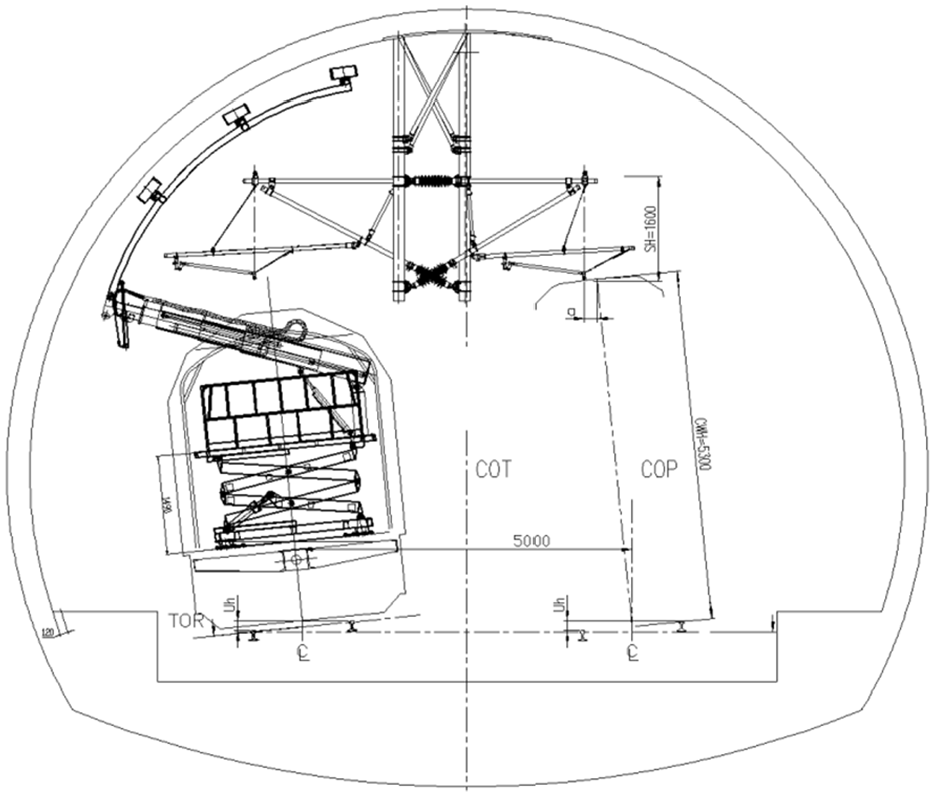
Schematic diagram of the detection condition.
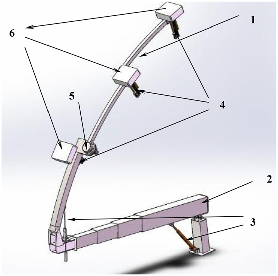
3D model of the mechanical arm.
The main design specifications are as follows:
(a) The telescopic stroke of the main arm is 3.4 m. The adjustable swinging angle is 60 degrees and the mass is about 850 kg. The total length of each section of the bent arm is 6 m, which meets the requirement of arch detection.
(b) The material of the main arm is steel, which concentrates the main mass of the mechanical arm. The material of the linear actuator is aluminum alloy and the shell material of the radar antenna is nylon. The linear actuator connected with the radar antenna is installed on the bent arm.
(c) The main arm swinging is driven by one hydro-cylinder, the telescopic action is driven by two hydraulic servo cylinders in the sleeve, and the swinging of the bent arm is driven by one hydraulic servo cylinder.
(d) Each section of the bent arm is rotated by a servo motor.
The linear actuator, the bent arm swing cylinder, and the main arm telescopic cylinder have the ability of automatic adjustment in the stroke through the control system program. The load of the linear actuator is very small, and the adjustment speed and driving force are relatively stable. The main arm’s telescopic action has good linearity and no obvious vibration. The bent arm is a slender rod with light weight and the swing displacement has a great amplification effect on the displacement of the telescopic cylinder. Therefore, the dynamic characteristics of the bent arm have a great influence on the mechanical arm. The material here is usually selected as steel initially with a mass of about 100 kg, which has good elasticity. The design applicability will be explored by dynamic calculation in the subsequent chapters.
The criteria to evaluate the dynamic rationality of the mechanism are as follows:
(a) According to the requirement of the China railway locomotive and rolling stock vibration characteristic standard, the vibration main frequency of the long and large suspension support equipment loaded on various types of railway vehicles should not be less than 2.5 Hz, and it is suggested that the vibration frequency should be greater than 4 Hz. The transient shock vibration acceleration is controlled within 1g.
(b) According to the technical requirements of the WX25T (WX is a code name for special testing vehicles and 25T is the train model number in China) high-speed railway tunnel lining detection vehicle of China Railway Corporation (referred to as “technical requirements”), the longitudinal shock vibration amplitude of each antenna is limited to 30 mm, and the stable amplitude is controlled to 15 mm. The maximum detection velocity ranges from 5 to 10 km h−1, and the braking distance should be within 3 m of the flat slope except the empty braking distance. The vibration acceleration is controlled within 5 m s−2 to 5 km h−1 detection velocity and vibration acceleration is controlled within 8 m s−2 to 10 km h−1 maximum detection velocity.
(c) In addition, according to the data quality requirements for the GPR, it is required that the antenna radial shock amplitude should not be more than 12.5 mm and the stable amplitude should be controlled within 5 mm. It is better to control the radial vibration main frequency within 10 Hz (no greater than 15 Hz).
Establishment of the finite element model and inherent characteristic analysis of the mechanical arm
The main dynamic characteristics of the mechanical arm deployment attitude, especially the low-frequency oscillation characteristics, are concentrated on the bent arm because of the unique structural characteristics. During the detection of the running vehicle, the main arm is stable, which is relatively static with the vehicle. The high-speed railway track irregularity can be neglected in the low-velocity condition. Therefore, the main arm is not considered in the modeling.
Then, the bent arm model has been established using the finite element method formulations simulated in ABAQUS. The global seeds dimension is 0.01. The model is divided into 265,560 units.
The type and quality of the grid unit closely influence the accuracy, smoothness, and the spectrum of simulation results. In order to acquire the accurate solution of contact dynamics, the fine linear hexahedral hourglass-stiffness-control-type reducing-integral element C3D8R is divided into the mechanical arm in this article. 11 The finite element (FE) model is presented in Figure 4, and the basic parameters are presented in Table 1.

The FE model of the bent arm.
The basic parameters of each part and component.

The differential equations of motion represented by the displacement of free vibration Timoshenko beam (considered the torsional effect of the arm itself) are 22

The general dynamic vibration differential equation is

Let

According to the conventional theory of the simple harmonic vibration method, the equation solution was set up as follows

Substituting equation (4) into equation (3), we obtain

Meanwhile, the corresponding eigenvectors of the eigenvalues are the vibration modes of natural frequencies.
Lanczos algorithm is selected to perform the matrix operations through the linear perturbation frequency method, and the natural frequencies can be effectively solved using the ABAQUS program. Results of the natural frequency calculation are presented in Table 2.
Vibration natural frequencies of the bent arm.

Through the ABAQUS program, the low-frequency band was focused and the first six order natural frequencies of the bent arm were solved. The results of vibration modes were analyzed, including radial, longitudinal, and torsional (both radial and longitudinal displacements exist):
(a) The first six order frequencies are from 2.35 to 7.5 Hz;
(b) The first two order frequencies are the sensitive frequencies of the system, which may easily interact with each other;
(c) The vibration mode distribution is relatively average.
Simulation calculation analysis of radar antenna pedestal vibration characteristics
For dynamic problems, ABAQUS solutions are usually divided into implicit dynamics ABAQUS/Standard and explicit dynamics ABAQUS/Explicit. The ABAQUS/Standard was selected, which was carried out in two steps. The first step is to stabilize the initial state and prevent the analysis results from serious distortion. 23
The vibration characteristics of the radar antenna pedestals represent the dynamic characteristics of the bent arm and greatly affect the radar antenna data acquisition quality as well. The radar antenna pedestals are selected as the object.
There are two main working conditions for vibration excitation of radar antenna pedestals during detection. Radial vibration is caused by automatic distance tracking and fast obstacle avoidance of the bent arm. Longitudinal shock vibration is caused by braking which is obviously affected by velocity.
Bent arm radial vibration
The pressure range of fast obstacle avoidance is usually 2.0–4.0 MPa, and the pressure range of automatic distance tracking is usually 0.5–3.0 MPa. For the safety and rapid response requirements, the most disadvantageous working conditions are concerned. The maximum transient pressure of 4 MPa was applied in the working area of the hydro-cylinder to make it decay rapidly to 0 within 1 s and the bent arm will produce radial shock vibration. The radial vibration amplitude–frequency characteristics of three antenna pedestals were simulated. The simulation results are presented in Figures 5 and 6, and the results are summarized in Table 3.
The simulation of upper pedestal radial vibration displacement and spectrum.

The simulation of upper pedestal radial vibration acceleration and spectrum.
Radial vibration simulation results of each radar antenna pedestal.

From the results, the following can be observed:
(a) The vibration of the upper antenna pedestal is particularly intense.
(b) The antenna noncontact detection unadjusted interval is 50 mm. However, the peak value of vibration displacement at the upper antenna pedestal reaches 37 mm, the vibration displacement amplitude is 35 mm, and the peak value of acceleration approaches 5 m s−2. It is presented that the characteristic is not optimistic.
(c) The advantage frequencies correspond to the first- and fifth-order system natural frequencies. They are relatively close in the vibration acceleration spectrum.
Longitudinal shock vibration at 5 km h−1 vehicle velocity
According to the requirements of Railway Administrations for tunnel lining GPR nondestructive detection efficiency, China Academy of Railway Sciences has carried out field tests on the high-speed railway. The optimal data acquisition trace interval is 2–3 cm and the number of sampling points is 512. The maximum velocity under the corresponding condition was calculated as follows

The theoretical maximum detection velocity is 14.06 km h−1 and the velocity stability coefficient of the acquisition system is 0.8. Therefore, the actual maximum detection velocity is 11.25 km h−1, which is in accordance with the technical requirements.
Therefore, the simulation conditions should focus on the shock vibration caused by emergency stop. Different braking forces can be selected according to different velocity conditions.
The displacement curve of the braking system measured by the detection vehicle at 5 km h−1 running velocity is used as input to the FE model and the effective braking distance is 1.5 m.
The simulation results of the shock vibration characteristics are presented in Figures 7 and 8 and the results are summarized in Table 4.

The simulation of upper pedestal longitudinal shock vibration displacement and spectrum.
The simulation of upper pedestal longitudinal shock vibration acceleration and spectrum.
Longitudinal shock vibration simulation results of each radar antenna pedestal.

From the results, the following can be observed:
(a) The vibration of the upper antenna pedestal is particularly intense. The peak value of vibration displacement reaches 35 mm, the amplitude is nearly 30 mm, and the amplitude is within 5 mm after 8 s. The peak value of the acceleration exceeds 4 m s−2. The results presented above are in accordance with the technical requirements.
(b) The values of 4.75 and 6 Hz have been observed in the acceleration simulation spectrum, which correspond to the fourth- and fifth-order natural frequencies of the system. In terms of response frequency, the longitudinal vibration produces the coupling effect of torsional and radial vibration natural frequencies.
(c) From the simulation result of the bottom antenna pedestal, the peak vibration displacement decreases significantly and the first advantage frequency of vibration acceleration becomes 7.5 Hz.
Longitudinal shock vibration at 10 km h−1 vehicle velocity
For the out-of-gauge detection, the faster the detection velocity is, the worse the stability of the detection device will be.
If the braking distance is calculated according to the braking force at 5 km h−1, the braking distance is estimated to be more than 6 m, which does not satisfy the technical requirements. Therefore, the emergency braking force (maximum deceleration) is taken, and the effective braking distance is 3 m, which is in accordance with the technical requirements. Then the displacement curve of the braking system at 10 km h−1 is used as input to the FE model.
The simulation results of the shock vibration characteristics are presented in Figures 9 and 10 and are summarized in Table 5.

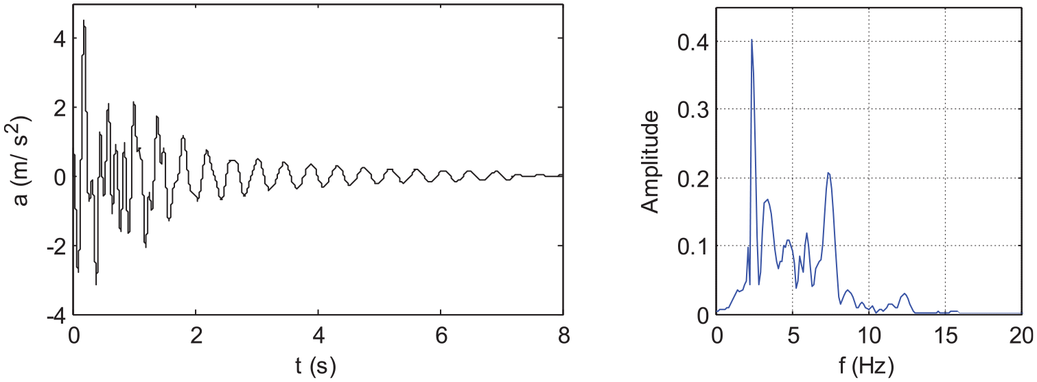
The simulation of upper pedestal longitudinal shock vibration displacement and spectrum at 10 km h−1.

The simulation of upper pedestal longitudinal shock vibration acceleration and spectrum at 10 km h−1.
Longitudinal shock vibration simulation results at 10 km h−1 of each radar antenna pedestal.
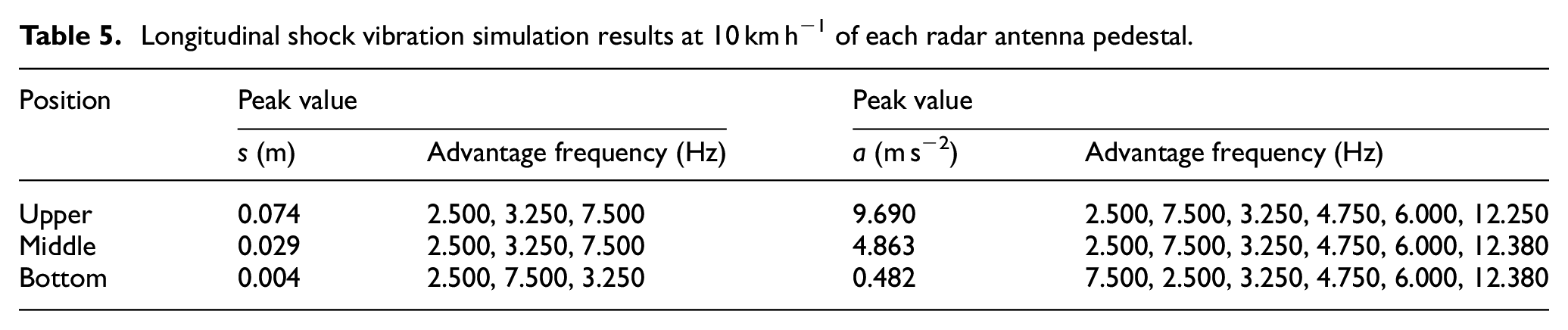
The following can be observed from the table:
(a) The advantage frequency, distribution rule, and system nonlinearity are basically the same when comparing the results at 5 km h−1.
(b) The first advantage frequency is 2.5 Hz, which exceeds the second-order natural frequency. The vibration time-domain characteristics of each radar antenna pedestal at 5 km h−1 velocity are linearly proportional to those obtained at 10 km h−1. However, the corresponding amplitude is far greater than the value specified in the technical requirements.
(c) The peak shock vibration displacement of the upper antenna pedestal is 74 mm, the displacement amplitude is about 55 mm, and the stable amplitude within 8 s is more than 10 mm. The peak vibration acceleration exceeds 8 m s−2, nearly 1g. These characteristics will cause great harm to the mechanical arm structure.
Summary
The detection velocity should be controlled within 5 km h−1 and the pressure loading and unloading curves of the bent arm swinging hydro-cylinder should be smooth.
In order to meet the technical requirements of 10 km h−1 detection velocity, the upper section of the mechanical arm could be cut off and the three antenna pedestals are distributed in the middle and bottom sections. However, this method will lead to the insufficient height of the detection line.
The results of the simulation analysis will be verified by the field dynamic test of the detection device in section “Field test of the detection device,” and then the optimization should be studied.
Field test of the detection device
Dynamic test
According to China Railway Corporation’s technical appraisement of newly developed products (Document No. 68 of Science and Technology 2014), in-plant functional verification and equivalence tests are required to be conducted.
Therefore, a high-speed railway tunnel and catenary model are built in the test site, the design parameters of which are equal to the sample parameters of 350 km h−1 speed grade high-speed railway tunnels in China. The internal filler is reinforced concrete. The model is shown in Figure 11 and the working condition is presented in Figure 12.

High-speed railway tunnel model.

Test conditions of the mechanism arm.
All sections of the bent arm are fully deployed and the radar antennas are driven to a distance of 150 mm from the tunnel model lining surface. Then, the running shock vibration and radial excitation test were, respectively, carried out. The 3D acceleration–velocity–displacement sensors of Institute of Mechanics, Chinese Academy of Sciences were installed on the radar antenna pedestals. The physical signal acquisition equipment is a 24-bit high-precision multi-channel data acquisition instrument.
Running shock vibration test
The numerical control (NC) traction trolley is attached to the detection device. The trolley is driven stably on the track at the velocities of 3, 5, and 7 km h−1, respectively. The longitudinal shock vibration characteristics of the three radar antenna pedestals were measured starting from stop braking.
From the simulation calculation results presented in section “Simulation calculation analysis of radar antenna pedestal vibration characteristics,” for safety reasons, the 10 km h−1 velocity is not included in the test conditions. The results of upper pedestal longitudinal shock vibration displacement tests are presented in Table 6.
Longitudinal shock vibration test record for each working condition.

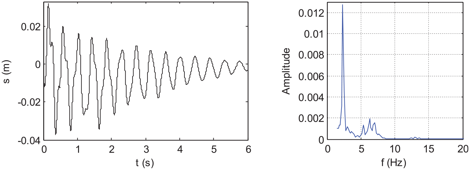
The vibration characteristic curves at 5 km h−1 velocity are presented in Figures 13 and 14 and the vibration test results are presented in Table 7.

Longitudinal shock Vibration displacement test curve and spectrum of the upper pedestal.

Longitudinal shock Vibration acceleration test curve and spectrum of the upper pedestal.
Vibration test results of each radar antenna pedestal.
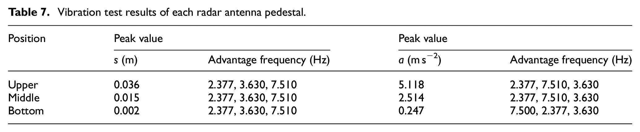
There will be slight discrepancies between the theoretical simulation results and the experimental records because of the slight difference from the development process and loading characteristics. However, it will not affect the main curve characteristics and the main frequency of longitudinal shock vibration.
It is indicated that the peak vibration displacements and accelerations from the experimental records and simulation results are approximately the same, with the maximum difference being less than 10%, and the trend of vibration curves is the same.
The measured peak vibration acceleration of the upper pedestal is a slightly greater than 5 m s−2 and attention should be paid again to the fact that the maximum detection velocity cannot exceed 5 km h−1.
Radial excitation test
The swinging hydro-cylinder is unloaded to 0 within 1 s after the radial pressure of 4 MPa is applied to the bent arm. The dynamic tests of the three pedestals were carried out and the data were recorded.
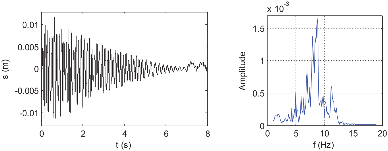
The measured peak vibration displacement of the upper pedestal is about 35.1 mm and the stable displacement amplitude within 8 s is about 12.5 mm. The results are presented in Figures 15 and 16.

Radial vibration displacement test curve and spectrum of the upper pedestal.

Radial vibration acceleration test curve and spectrum of the upper pedestal.
In addition, the measured peak vibration displacement of the middle pedestal is about 16.6 mm and the stable displacement amplitude within 8 s is about 5.5 mm.
The measured peak vibration displacement of the upper pedestal is about 8.7 mm and the stable displacement amplitude within 8 s is about 2.5 mm.
From Figure 16, the peak vibration acceleration reaches 4.2 m s−2, and the advantage response frequencies are 2.33 and 6.17 Hz. The vibration amplitude and frequency characteristics from the experimental records correspond approximately with the simulation results.
Analysis of the radar detection data
The antenna is sensitive to the radial dynamic characteristics while the longitudinal dynamic characteristics have no obvious influence on the antenna because of the detection fundamental of GPR. Through the dynamic test, the main response frequencies of the three radar antenna pedestals are far below 15 Hz. Therefore, the radar data characteristics under different radial vibration displacement amplitudes were analyzed to verify whether the detection device is working in accordance with the technical requirements of actual field detection.
According to the radial vibration characteristics of the dynamic test, the shock vibration displacement amplitude and stable amplitude of the upper pedestal exceed the limit value of the requirement, while the results of the middle and bottom pedestals are within the reasonable range. After processing the test data with the same macro instruction, the radar images are obtained, which are shown in Figure 17.

Radar images of antenna pedestals: (a) bottom, (b) middle, and (c) upper.
From the images, the following can be observed:
(a) The data quality of the bottom pedestal is the best, which could clearly identify the number of reinforcing bars and the trend of the reinforcing bar layout. The tunnel lining structure characteristics are obvious without clutter and the layering line is clear.
(b) The data quality of the middle pedestal is the second and the quantity of reinforcing bars is unclear, which could only identify the number of reinforcing bars. The structural characteristics are affected, the discontinuous layering line is visible, and the clutter is distributed in the deep part of the image.
(c) It is difficult to distinguish the number and trend of reinforcing bars in the upper pedestal’s radar image. The layering line is difficult to observe and the clutter is visible obviously.
It can be clarified that the radial vibration amplitude exceeding the limit value of technical requirements has a great impact on the image recognition effect. Therefore, it is verified again through the test data quality that the bent arm needs to be optimized to improve its adaptability.
Impact analysis of bent arm material optimization on radar antenna pedestal vibration characteristics
As the novelty of the detection device should be ensured, only the material will be optimized. In order to effectively improve the natural frequency and significantly reduce the weight of the bent arm, carbon fiber material with a density of 1800 kg m−3, an elasticity modulus of 300 GPa, and a Poisson ratio of 0.307 will be selected.
Inherent characteristic analysis of the mechanical arm
Through the ABAQUS program, the first six order natural frequencies can be obtained using the solutions presented in section “Establishment of the finite element model and inherent characteristic analysis of the mechanical arm” (Table 8).
Vibration natural frequencies of the carbon fiber bent arm.
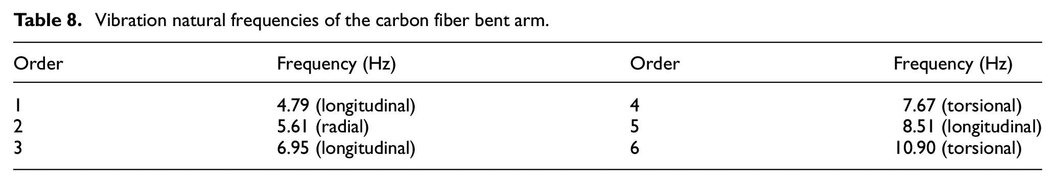
The following can be observed from Table 8:
(a) The spacing of the first six order frequencies is more regular, and all the frequencies are greater than the corresponding order natural frequencies of the steel material.
(b) The vibration modes are significantly different from each steel material. Especially, the first-order longitudinal natural frequency is reasonable to avoid the sensitive frequencies of railway locomotives, rolling stock, and mobile equipment.
(c) The radial vibration natural frequencies including the torsional vibration frequencies are lower than the sensitive frequencies of the GPR signals.
From the inherent characteristics, the carbon fiber material has an obvious advantage.
Then, the simulation calculation and analysis will be carried out under the same working condition, loading mode, and boundary conditions as in section “Simulation calculation analysis of radar antenna pedestal vibration characteristics.”
Bent arm radial vibration
The simulation results are presented in Figures 18 and 19 and the results are summarized in Table 9.

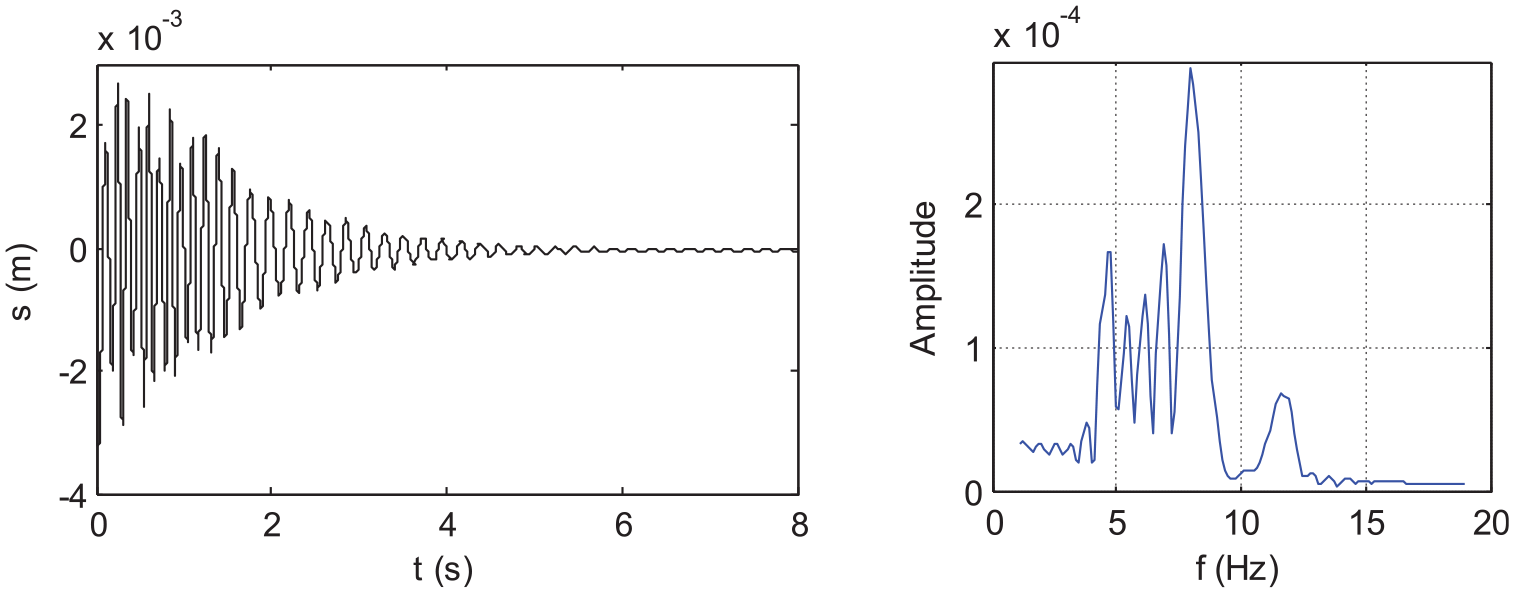
The simulation of upper pedestal radial vibration displacement and spectrum in carbon fiber bent arm.
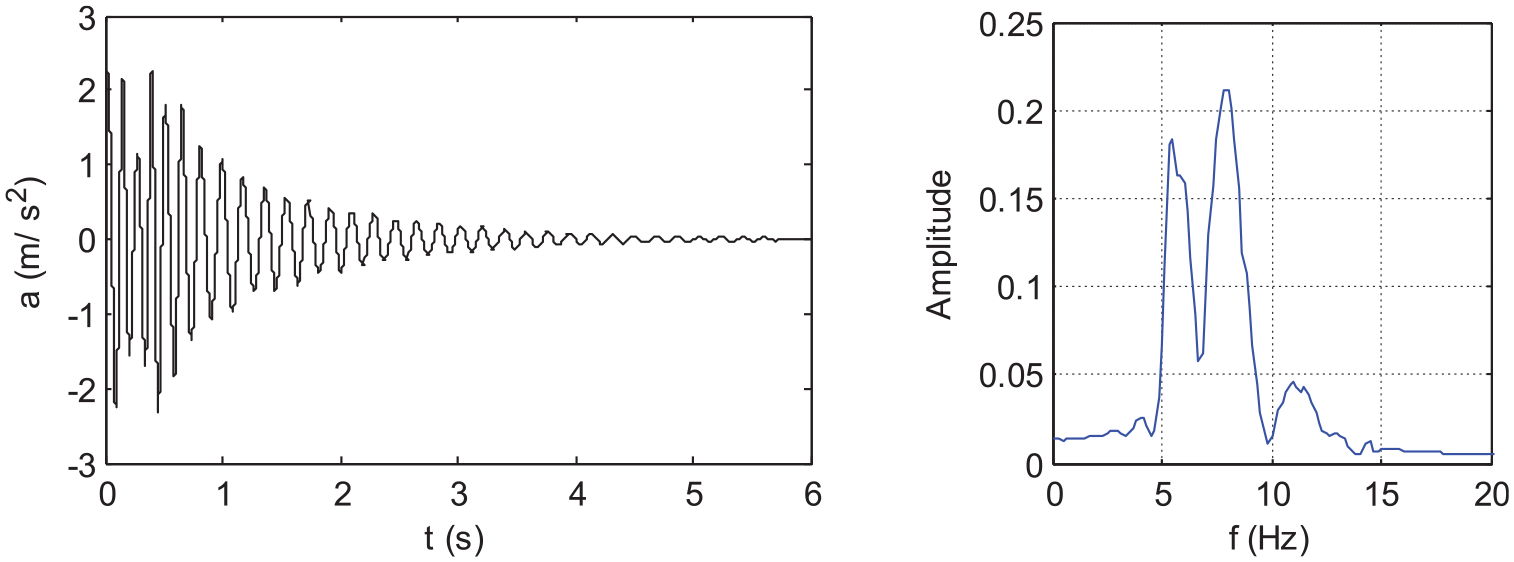
The simulation of upper pedestal radial vibration acceleration and spectrum in carbon fiber bent arm.
Radial vibration simulation results of each radar antenna pedestal in carbon fiber bent arm.
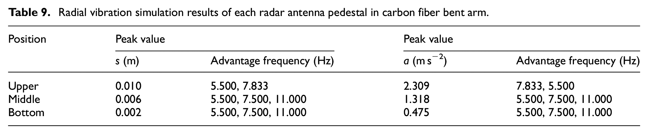
The following can be observed from the table:
(a) The peak value of radial vibration displacement of the upper pedestal has decreased by 70% to 10 mm, and the peak value of vibration acceleration has decreased over 50% compared with the vibration characteristics of the steel bent arm.
(b) The advantage frequencies of 5.5 and 7.5 Hz correspond to the second- and fourth-order system natural frequencies. In addition, the response frequency of 11 Hz is excited in the vibration characteristics of the middle and bottom pedestals, which corresponds to the sixth-order natural frequency.
Longitudinal shock vibration at 5 km h−1 vehicle velocity
The simulation results are presented in Figures 20 and 21 and are summarized in Table 10.
The simulation of upper pedestal longitudinal shock vibration displacement and spectrum in carbon fiber bent arm.
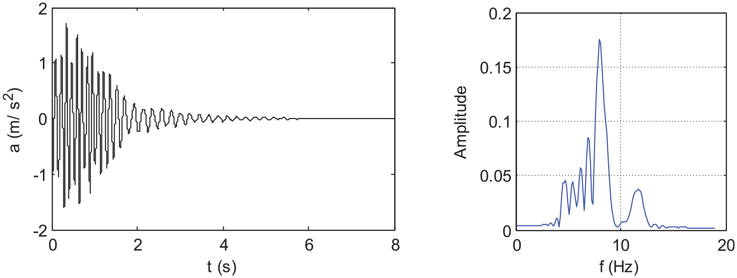
The simulation of upper pedestal longitudinal shock vibration acceleration and spectrum in carbon fiber bent arm.
Longitudinal shock vibration simulation results of each radar antenna pedestal in carbon fiber bent arm.

The following can be observed from the table:
(a) The peak value of shock vibration displacement of the upper pedestal has decreased around 92% to 3.2 mm, and the peak value of vibration acceleration has decreased over 62% compared with the vibration characteristics of the steel bent arm.
(b) There are several advantage frequencies that basically correspond to all the system natural frequencies except the fifth-order one. The dispersion of response frequency is beneficial to reduce the possibility of resonance.
(c) The main frequency is 8 Hz, which is between the fourth- and fifth-order natural frequencies. The vibration attenuation is very fast and the amplitude–frequency characteristics are very ideal.
Longitudinal shock vibration at 10 km h−1 vehicle velocity
The simulation results are presented in Figures 22 and 23 and are summarized in Table 11.
The simulation of upper pedestal longitudinal shock vibration displacement and spectrum in carbon fiber bent arm at 10 km h−1.

The simulation of upper pedestal longitudinal shock vibration acceleration and spectrum in carbon fiber bent arm at 10 km h−1.
Longitudinal shock vibration simulation results of each radar antenna pedestal in carbon fiber bent arm at 10 km h−1.

The following can be observed from the table:
(a) The amplitude–frequency characteristics are different when comparing the results at 5 km h−1 detection velocity. The vibration energy is enhanced and the vibration attenuation time increases significantly. In view of the frequency domain, the nonlinearity of the carbon fiber material bent arm at 10 km h−1 velocity has been enhanced.
(b) Comparing the results in the 5 km h−1 detection velocity running condition, the peak value of shock vibration displacement of the upper pedestal was increased nearly four times to 11.7 mm, and the acceleration peak value was increased nearly five times to 7.556 m s−2. The peak value of shock vibration displacement of the middle pedestal was increased nearly three times, and the acceleration peak value is increased over four times to 4.192 m s−2. Only the dynamic time-domain characteristics of the bottom pedestal present linear multiple relationships.
(c) The amplitudes mentioned above are well controlled within a reasonable range of dynamic characteristics. Comparing the results of the steel material bent arm in the 10 km h−1 detection velocity running condition, the peak value of shock vibration displacement of the upper pedestal is decreased 84%; the peak value and amplitude are far below the maximum allowable value of the technical requirement and even lower than the results of the steel material bent arm in the 5 km h−1 detection velocity running condition; the peak acceleration is decreased nearly 22% and successfully controlled within 8 m s−2.
(d) These characteristics are of great benefit to the safety of the mechanical arm structure, and the main response frequency and amplitude are within the range of radar detection data requirements.
Summary of vibration characteristics of different materials
The longitudinal shock vibration peak values of the two materials at 5 and 10 km h−1 detection velocities are plotted and compared as shown in Figures 24 and 25. It is obviously shown that the optimization of the carbon fiber material for the bent arm makes its vibration characteristics insensitive to the 10 km h−1 detection velocity, which is of great significance to the feasibility of detection velocity increase.

Comparisons of simulation results of peak vibration displacement.

Comparisons of simulation results of peak vibration acceleration.
Conclusion
The detection of lining state is of great significance to the health diagnosis of high-speed railway tunnels. In this article, a more targeted and technologically advanced detection device has been designed and developed. This special device based on the multi-stage rotating mechanism carries three GPR antennas to collect the internal data of the lining and cover the whole arch detection range on one side.
The radial vibration and the longitudinal shock vibration characteristics at the detection velocity of 5 km h−1 of the steel bent arm could meet the technical requirements. Especially, when the bent arm material is optimized as carbon fiber, it is of great significance that the dynamic characteristics are excellent at the maximum detection velocity of 10 km h−1 and can be still in accordance with all the technical requirements.
Through the simulation analysis and field test, the results indicate that the leap of detection mode from theoretical design to field application is achieved.
Footnotes
Appendix 1
Acknowledgements
This project is focused on the research and development of a detection device for the high-speed railway tunnel lining in China. The authors would like to express their heartfelt thanks to all the researchers who provided assistance during the study.
Handling Editor: José Correia
Declaration of conflicting interests
The author(s) declared no potential conflicts of interest with respect to the research, authorship, and/or publication of this article.
Funding
The author(s) disclosed receipt of the following financial support for the research, authorship, and/or publication of this article: This study was supported by the Key Project of Science & Technology Research of China Academy of Railway Sciences (CARS) through “Study on The Influence Dynamics Factors of Tunnel Lining Detection Device and Processing Algorithm Parameters Optimization of GPR Detection Data” (Award No. 2019YJ157).