
Abstract
Some equipment have low efficiencies and safety when their surfaces are covered with ice, such as wind turbine and airplane, so de-bonding ice on such kind of equipment surface is necessary. In this article, the ultrasonic de-icing method based on icing aluminum plate is researched by finite element method. First, the natural frequency of icing aluminum plate changing with thickness of ice is simulated by modal analysis. Then, the distributions of shear stresses at the interface between aluminum plate and ice layer changing with excitation frequencies are simulated by harmonic analysis. Second, the shear stress and de-icing area influenced by the size of piezoelectric ceramic and excitation voltage are analyzed. The simulation results show that there is lowest natural frequency with optimum thickness of ice layer used to de-bond ice for ultrasonic de-icing system. The optimum distribution law of shear stress at the interface between ice layer and aluminum is decided. In this condition, the shear stress and de-icing area increase along with the excitation voltage. However, the de-icing area increases slowly. All the simulation results lay a theoretical foundation for future experiments and application of ultrasonic de-icing.
Introduction
Icing on equipment, such as wind turbine and airplane, may cause low efficiencies and economic losses, sometimes even endanger people’s lives.1–4 Therefore, some scholars carried out a lot of researches on icing. For example, Y Li researched the processes and shapes of icing on blades of horizontal- and vertical-axis wind turbines by icing wind tunnel experiments. The research results disclose the influences of icing on aerodynamic characteristics of wind turbine.5–7 In addition, researchers such as X Yi et al.8–10 researched the processes of icing on surface of airplane wings and modeled the three-dimensional shape of icing by simulations. Above research results lay the theoretical and experimental foundations for developing the methods of de-icing. Therefore, developing an efficient de-icing method is valuable to promote working efficiency of equipment and save people’s life.
Now, some de-icing methods are researched, such as electro-thermal de-icing method, fluid-thermal de-icing method, pneumatic impulse de-icing method, electro-impulsive de-icing method, microwave de-icing method, surface coating de-icing method, and ultrasonic vibration de-icing method.11–14 Among these de-icing methods, the ultrasonic vibration de-icing method has characteristics of low energy consumption, small amplitude, light weight, quietness, simple configuration, and easy installation, but this technology has not been advanced and being researched widely right now.15–18
JL Palacios et al. 19 developed the mathematical model of shear stress concentration coefficients at interface and measured by experiments. T Haihui et al. 20 researched the optimal position of piezoelectric ceramic and de-icing frequency by ANSYS based on mathematical model. H Habibi et al.21,22 simulated the propagation of short wave and shear stress at interface between ice layer and wind turbine blade. N Diplacido et al. 15 found that burst excitation by ultrasonic vibration could remove larger area of icing on rotorcraft by simulation and experiment. Z Wang et al. 13 removed a slice of ice freezing on leading edge surface of aircraft wing by experiment. In general, the research methods of ultrasonic de-icing mainly depend on analytic method, simulation method, and experimental method. The mathematical model established by analytic method is only suitable to infinite boundary composite plate. It can analyze the changing law of shear stress concentration coefficient with frequency and wave velocity. However, the distributions of shear stresses at interface between substrate and ice layer are commonly simulated and optimized by finite element method (FEM), but the changing law of it is seldom researched. The feasibility study of ultrasonic de-icing is verified by experiments based on the theoretical researches. However, the test parameter on de-icing effect is only time length from power on to the moment of ice shedding. The adhesion strength of ice layer changing with the excitation frequency is seldom researched by experiment. In comparison, the natural frequency changing with the size of icing layer and the shear stresses changing with the excitation voltage are seldom researched.
In this article, the natural frequency of icing aluminum plate changing with the thickness of ice layer is simulated by ANSYS. The distribution law and the values of shear stress at the interface between aluminum plate and ice layer changing with the frequency, size of piezoelectric ceramic, and excitation voltage are also researched by ANSYS. The optimum distribution law of shear stress is decided. It lays the theoretical foundation for future experimental researches.
Simulations and analyses
Vibration mode of icing aluminum plate
In this article, the icing aluminum plate is selected as a research object. It comprises aluminum plate and ice layer. The aluminum plate is the icing substrate. The schematic diagram of icing aluminum plate is shown in Figure 1.
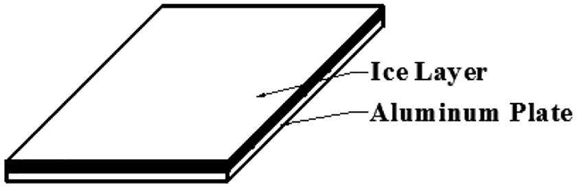
Schematic diagram of icing aluminum plate.
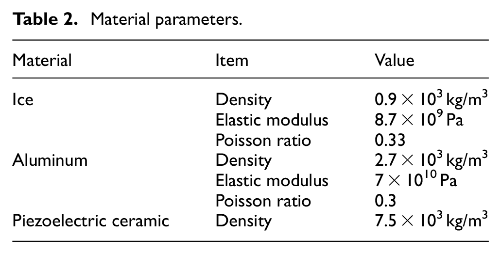
For studying the changing law of natural frequency of icing aluminum plate influenced by the thickness of ice layer, the model analysis of icing aluminum plate is simulated by ANSYS. In this article, two sizes of thicknesses of aluminum plates are selected, they are 1 and 2 mm, respectively, and all the side lengths of them are 80 × 80 mm2. The element details and material parameters are listed in Tables 1 and 2. The four edges of icing aluminum plate are fully constrained, and the coupled relationship between ice layer and aluminum plate is assumed to be adhered together by VGLUE command.
Element type selected in simulation.
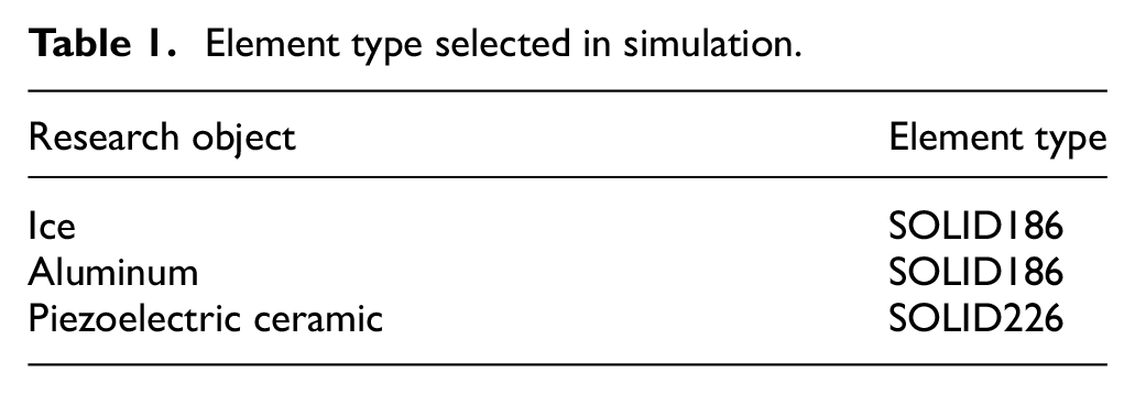
Material parameters.
Elastic matrix E as a stiffness form for piezoelectric ceramic is listed as follows

Piezoelectric matrix e for piezoelectric ceramic is listed as follows

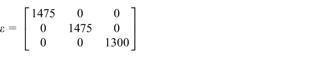
Relative permittivity ε for piezoelectric ceramic is listed as follows
The icing aluminum model whose thicknesses of ice layer and aluminum plate are both 1 mm is selected for convergence study. The simulation results are listed and shown in Table 3 and Figure 2. In this article, the icing aluminum plate model is meshed by mapped method. From Table 3 and Figure 2, when the number of nodes are higher than 8169, the frequency has a little change. In this article, the number of nodes selected is 17,949. In this condition, each element size is 2 × 2 × 0.5 mm3.
Natural frequencies in different numbers of nodes.


Changing of natural frequency with the number of nodes.
The cloud picture of the fourth-order vibration mode and its variation in natural frequency along with the thickness of ice layer are shown in Figures 3 and 4, respectively.

Cloud picture of the fourth-order vibration mode of icing aluminum plate.

Changing law of natural frequency along with the thickness of ice layer.
From Figure 3, the cloud picture is the fourth-order bending mode of icing aluminum plate, when all edges of it are constrained. It shows that the bending deformation along the thickness of ice layer is centrally symmetric.
From Figure 4, it shows that when the thickness of the aluminum plate is constant (1 or 2 mm), the natural frequency of icing aluminum plate decreases first and then increases with the increase in the thickness of ice layer. It means that the icing aluminum plate has lowest natural frequency and optimum thickness of ice layer (1 mm or 2 mm) to be de-bonded from aluminum plate when the mode of de-icing and the thickness of substrate are constant. In this condition, the excitation frequency and energy consumption of ultrasonic de-icing system are lowest.
The reason for such changing law of natural frequency is that the stiffness of ice layer is far lower than the one for aluminum plate. When the thickness of ice layer is thin, the increasing speed of composite stiffness of icing aluminum plate is lower than the one of weight. Therefore, the natural frequency of icing aluminum plate is low as the thickness of aluminum plate is thin. However, the increasing speed of composite stiffness of icing aluminum plate is gradually higher than the one of weight as the thickness of ice layer increases. It results in the increase in natural frequency.
In addition, when the thickness of aluminum plate is 2 mm, the natural frequency of icing aluminum plate is higher than the one with 1-mm-thick aluminum plate. The calculation results show that the stiffness of aluminum plate substrate has great influence on the natural frequency of icing aluminum plate. Therefore, ultrasonic de-icing system should have different de-icing frequency and optimal de-icing thickness under different substrate thicknesses conditions. When developing and designing an ultrasonic de-icing system, the excited frequency of driving power supply should match the natural frequency of icing aluminum plate.
Distribution of de-icing shear stress
According to the previous research result, the adhesive force at interface between ice layer and metal substrate in tangential direction is much lower than the one in vertical direction. Therefore, exploring and acquiring the distribution law of shear stress at interface between ice layer and aluminum plate is the research core of ultrasonic de-icing method in this article. In this article, ultrasonic vibration of icing aluminum plate is excited by converse piezoelectric effect, and the bending deformation and shear stress along thickness are generated under this excitation. When the shear stress at interface between ice layer and aluminum plate is higher than the adhesive shear stress in tangential direction, the ice layer will separate from aluminum substrate.
The shear stress and its distribution at interface between ice layer and aluminum plate changing with the increase in the excitation frequency are simulated by harmonic response analysis based on mode analysis. According to modal analysis results, four pieces of piezoelectric ceramics (PZT4) are selected and placed on the unfrozen surface of aluminum plate substrate. The schematic diagram is shown in Figure 5.

Schematic diagram of layout of piezoelectric ceramics: (a) transverse view of icing aluminum plate and (b) back of icing aluminum plate.
From Figure 5, the size of each piezoelectric ceramic is 20 × 20 × 2 mm3 and the thickness of ice layer is 1 mm. The peak-to-peak excitation voltage Vp-p is 400 V and the excitation frequency is from 0 to 100 kHz. The simulation results are shown in Figure 6. In this article, the XY shear stress in ANSYS is selected as maximum shear stress, because the adhesive interface between ice layer and aluminum plate is parallel to XY plane of coordinate system when establishing icing aluminum plate model.

Changing law of shear stress at interface with excitation frequency.
According to the previous research result, the adhesive shear stress of ice layer with metal substrate in tangential direction is about 1.8 MPa. 23 From Figure 6, there are several excitation frequencies at which the maximum shear stresses at interface between ice layer and aluminum plate are higher than the adhesive shear stress of ice layer in tangential direction. When excitation frequencies are 71, 91, and 97 kHz, maximum shear stresses at these frequencies are higher than adhesive shear stress. They are 5.4, 9.5, and 12 MPa, respectively.
The reason for these conditions is that the resonances of icing aluminum plate near these frequencies happen and they make icing aluminum plate generate large amplitude of bending deformation and shear stress. The simulation results show that the method of ultrasonic micro-vibration may remove ice on the aluminum plate surface. The cloud pictures of shear stress distributions at these excitation frequencies are shown in Figure 7.

Cloud picture of shear stress distribution at interface: (a) 71 kHz, (b) 91 kHz, and (c) 97 kHz.
From Figure 7, the distributions of shear stresses are different at these frequencies. When the excitation frequency is 71 kHz, the distribution law of shear stress at interface is shown in Figure 7(a). The shear stress centrosymmetrically distributes, and the part near four corners of icing aluminum plate is lower than the one in the center. In the case of this distribution law, ultrasonic de-icing method is suitable to remove ice locating at the center and the edges of icing aluminum plate.
When excitation frequency is 91 kHz, the distribution law of shear stress at interface is shown in Figure 7(b). The distribution of shear stress at this frequency has no obvious characteristic. It is approximately axially symmetric distribution, and shear stress at some local regions is higher than adhesive shear stress. According to this distribution law, the ultrasonic de-icing method is suitable to remove lumpy and discontinuous ice layer.
When excitation frequency is 97 kHz, the distribution law of shear stress at interface is shown in Figure 7(c). The positive shear stresses and negative ones alternatively distribute at this frequency. It is beneficial to shed off ice layer from substrate.
In addition, a parameter P, named “de-icing area ratio,” is defined to quantify de-icing area accounting for the proportion of whole interface area according to the shear stress at interface higher than adhesive shear stress of ice layer. The definition of de-icing area ratio is the proportion of de-icing area accounting for the whole area of adhesive interface. The de-icing area is the region at interface whose shear stress is higher than adhesive shear stress of ice layer. The parameter P is expressed in the following formula

where P is the de-icing area ratio, S1 is the area where the shear stress at interface is higher than the adhesive strength of ice layer, and S is the interface area of icing aluminum plate.
According to the simulation results, the de-icing area ratios in three excitation frequencies are listed in Table 4.
De-icing area ratio at three excitation frequencies.

From Table 4, the de-icing area ratio and the shear stress are both higher at an excitation frequency of 97 kHz. Therefore, the distribution law of shear stress at this frequency is selected as optimal de-icing distribution law for icing plate.
Size of piezoelectric ceramic
When the size of the aluminum plate, position of piezoelectric ceramics, and the excitation voltage are constant, the sizes of piezoelectric ceramics are reduced to 16 × 16 × 2 mm3. The maximum shear stresses at interface between ice layer and aluminum plate changing along with the excitation frequency are simulated by harmonic analysis and the results are shown in Figure 8.
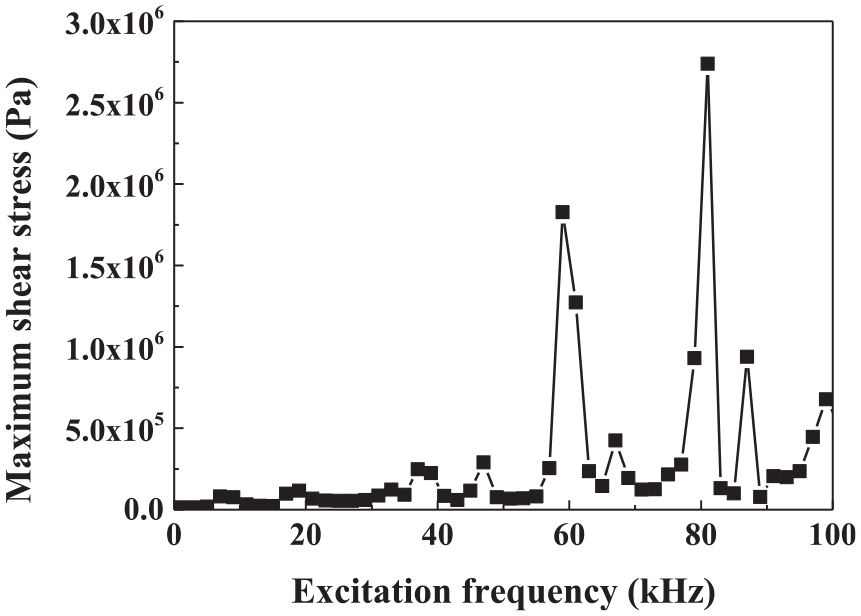
Changing of maximum shear stress at interface along with excitation frequency.
From Figure 8, it can be observed that when the excitation frequency is 81 kHz, the maximum shear stress at interface is highest and its value is 2.74 MPa. The distribution of shear stress is shown in Figure 9.

Distribution of shear stress at interface.
When the size of PZT4 is 16 × 16 × 2 mm3, the excitation frequency, which generates maximum shear stress at the interface, decreases comparing with the one as PZT4 size is 20 × 20 × 2 mm3.
The reason for the decrease in the natural frequency is that the composite stiffness of the icing aluminum plate decreases along with the size of piezoelectric ceramic. It causes the natural frequency of icing aluminum plate to decrease.
The results show that the size of piezoelectric ceramics decreases by 36%, but the maximum shear stress decreases by 77.2%. It means that shear stress at interface will decrease significantly with the reduction in size of piezoelectric ceramic.
From Figure 9, the distribution law of shear stress at interface in this condition is similar to that of icing aluminum plate whose PZT4 size is 20 × 20 × 2 mm3. The positive shear stresses and the negative ones approximately alternatively distribute. In contrast, the area of each local shear stress region becomes greater.
It causes the positive shear stress regions or negative ones to overlap. In addition, the regions whose shear stress at interface is lower than adhesive strength of ice layer become greater. They locate at the interval between positive shear stress region and negative one.
According to the simulation results, the de-icing area ratio is 7.25%. Its reduction is 64.65%, and the ultrasonic vibration nearly has no ability of de-icing.
Variation in excitation voltage
The change in the shear stress at interface and de-icing area ratio along with excitation voltage are also researched based on above two icing aluminum plate models. The calculation results are shown in Figure 10.

Maximum shear stress and de-icing area ratio changing along with the excitation voltage: (a) size of piezoelectric ceramic is 20 × 20 × 2 mm3 and (b) size of piezoelectric ceramic is 16 × 16 × 2 mm3.
From Figure 10(a), when the sizes of aluminum plate substrate and piezoelectric ceramics are constant, the maximum shear stress at interface and de-icing area ratio are simulated and analyzed with the variation in excitation voltage, peak to peak, changing from 200 to 1000 V. According to the simulation results, the maximum shear stress at interface increases linearly with the increase in the excitation voltage. However, the de-icing area ratio increases nonlinearly and slowly with the increase in the excitation voltage. When excitation voltage Vp-p is 600 V, the de-icing area ratio is 84.3%. When excitation voltage Vp-p is 1000 V, the de-icing area ratio is 86.8%. The growth of de-icing ratio is only 2.5%.
From Figure 10(b), when the size of piezoelectric ceramic is 16 × 16 × 2 mm3, the maximum shear stress at interface also increases linearly with the excitation voltage. When the excitation voltage Vp-p is 200 V, the de-icing area ratio is 0. The result means that ultrasonic de-icing system has no ability of de-icing under this excitation voltage condition. With the increase in the excitation voltage, the de-icing area ratio begins to increase, and first grows fast and then slowly.
Discussion
The simulation results in this article show that when ultrasonic vibration is used to remove ice freezing on the surface of aluminum plate substrate, there is an optimal thickness of ice layer selected to be removed. In this condition, the natural frequency of icing aluminum plate is lowest, and the efficiency is high. In addition, there is a relationship between distribution law of the shear stress at interface and excitation frequency. When the positive shear stress and negative one alternatively distribute, the shear stress at interface and de-icing area ratio are higher. Therefore, this kind of distribution law should be preferred and selected first in designing ultrasonic de-icing system.
When the size of aluminum plate substrate is constant, the shear stress and de-icing area ratio reduce rapidly with the decrease in the size of piezoelectric ceramics. The shear stress is influenced by this factor more significantly than de-icing area ratio.
When excitation voltage increases, the shear stress and de-icing area ratio also increase. The ability of ultrasonic de-icing can be improved by this way. However, it has a limit. The reason is that with the increase in the excitation voltage, the de-icing area ratio increases slowly and the efficiency of de-icing becomes low. For designing an efficient ultrasonic de-icing system, reasonable excitation voltage based on distribution law of shear stress and de-icing area ratio at interface should be selected in order to improve efficiency and save energy.
In addition, according to the simulation results, although de-icing area ratio of ultrasonic de-icing system is up to more than 80% at interface, there are still some regions where the shear stresses are lower than the adhesive shear stress of ice layer. The ice layer in these regions will decline the ability of ultrasonic de-icing, especially in the case of icing on the whole surface of aluminum plate substrate. These regions whose shear stresses are lower than adhesive shear stress of ice layer will obstacle the ones whose shear stresses are higher than the adhesive shear stress of ice layer.
Conclusion
In this article, the ultrasonic de-icing method, which removes ice layer on aluminum plate, is studied preliminarily by FEM. Some conclusions are acquired as follows:
When the thickness of aluminum plate is constant, the natural frequency of icing aluminum plate in the fourth-order mode first decreases and then increases with the increase in the ice layer thickness. There is lowest natural frequency. The stiffness of aluminum plate has great influence on composite stiffness of icing aluminum plate.
The maximum shear stress at interface is higher than adhesive shear stress of ice layer when the excitation frequencies are 71, 91, and 97 kHz. The distribution law, in which the positive shear stress and negative one alternatively distribute at interface, has higher shear stress and de-icing area ratio. The size of piezoelectric ceramic has great influence on maximum shear stress and de-icing area ratio at interface.
When the sizes of ice layer, aluminum substrate, and piezoelectric ceramic are constant, the maximum shear stress at interface increases linearly with the increase in the excitation voltage. The de-icing area ratio increases nonlinearly and grows slowly with the increase in the excitation voltage.
Footnotes
Handling Editor: James Baldwin
Declaration of conflicting interests
The author(s) declared no potential conflicts of interest with respect to the research, authorship, and/or publication of this article.
Funding
The author(s) disclosed receipt of the following financial support for the research, authorship, and/or publication of this article: This work was supported by the following funding: (1) The National Natural Science Foundation of China (NSFC; Grant No. 51976029), (2)“Young Talents” Project of Northeast Agricultural University (Grant No. 17QC32), and (3) The State Key Laboratory of Alternate Electrical Power System with Renewable Energy Sources (Grant No. LAPS19007).