
Abstract
Lightweight automobile body structure, made of aluminum, can extend the endurance mileage of electric automobile. However, the mechanisms for the application of aluminum in automobile body structure are not clear until now. The main contribution of this work is to propose a method of equivalent substitution criteria of aluminum for steel. This method researches small deformation and large deformation under bending mode. First, formulations of cross-sectional properties, including open, single-cell, double-cell, three-cell, and four-cell sections, are derived, and equivalent substitution criteria in the case of small deformation, which include equal stiffness design and equal strength design, are initially proposed. Second, in the case of large deformation, the steel circular tube and channel tube are substituted by aluminum tube under equivalent stiffness. The bending resistance of five types of tubes, including rectangular hollow section, rectangular hollow section with double-cell, rectangular hollow section with triple-cell, mild steel, and high-strength steel tube, are, respectively, compared considering crashworthiness under equal mass. Third, the side frame and chassis frame examples verify the effectiveness of the proposed method, which is universal and can also be applied in aerospace structures.
Introduction
Because of the shortage of fossil energy and the strict environmental protection, electric vehicles are put into the routine to replace the traditional fuel ones. However, the endure mileage limits the development of electric automobile. Lightweight design is one of the effective methods to improve the endurance mileage.1–4
Generally, lightweight design of automobile can be conducted by structural analysis and optimization,5–21 material substitution,22–24 and new forming process.25–27 For decades, structural optimization has been maturely applied in automobile industry.28–33
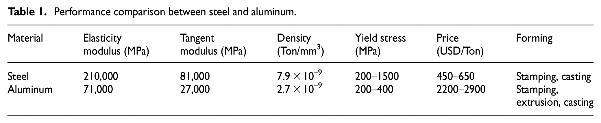
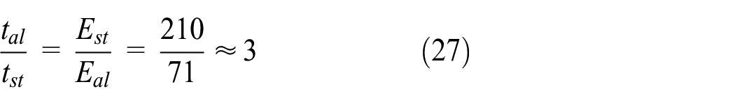
Recently, the substitution of aluminum tube, combined with extrusion process, is introduced to further reduce the structural weight without loss of mechanical performance. According to Table 1, the ratios of stiffness (elasticity modulus) and mass (density) for these two materials are 2.95 and 3, respectively. The value is approximately equal and is 3. So it cannot achieve the goal of lightweight that we only take elasticity modulus and density into consideration for equivalent substitution criteria of aluminum for steel.
Performance comparison between steel and aluminum.
As for forming process, the parts in traditional steel body are manufactured by stamping 34 or casting,35,36 and then spot-welded together. For example, Figure 1 shows a B-Pillar structure of Porsche made of steel. In order to improve the crashworthiness of body side frame, inner waist and outer waist reinforcements are stamped and then welded together with B-Pillar inner and rocker rear reinforcements. Meanwhile, manufacture cost is increased. On the contrary, aluminum tubes can be directly extruded to form complex cross-sectional shape without spot-welded. 37 Thus, the extrusion process can take advantage of aluminum to simplify manufacturing process and reduce manufacturing cost.

B-Pillar structure of Porsche made of steel.
Although the aluminum tube can be extruded to form the above complex structure, 38 it is necessary to rationally study the equivalent substitution mechanism of tube. Accordingly, the deformation mechanism of tube should be taken into consideration. Ashab et al.39,40 studied the mechanical performance of aluminum hexagonal honeycombs with different cell sizes and wall thickness combined compression-shear loads. Liu 41 researched the axial crashes of regular thin-walled box section tubes and employed simplified models for the design optimization. Nia and Parsapour 42 analyzed energy absorption capacity of multi-cell thin-walled tubes made of aluminum and verified that the energy absorption capacity of multi-cell sections is greater than that of simple sections. Isaac and Oluwole 43 obtained a theoretical formation of the total energy absorption and the mean crushing force of a circular thin-walled tube without crack defect and then investigated the influences of the tube thickness to the energy absorption capacity. Also, the axial crushing resistance of a new type of embedded multi-cell tubes was researched by Zhang et al. 44 and they analyzed the deformation-force response and energy absorption during the crushing process. Shen et al. 45 studied the axial compression of multi-cell thin-walled tubes made of aluminum alloy, derived an analytical formulation for predicting mean crush force, and optimized the thickness and arrangements of internal ribs of unequal triple-cell tube. In summary, the theories of axial crash of tube have been intensively investigated. The collision resistance can be improved by multi-cell configurations,46,47 which are more beneficial for aluminum than steel, because the extrusion process can effectively produce the tube with multi-cell configurations. Therefore, the equivalent substitution mechanism of tube under axial compression mode is no longer covered in this article.
On the contrary, the bending collapse behavior of rectangular tubes was also initially studied theoretically and experimentally by Kecman, 48 and the predictions of the hinge moment–rotation curves and energy absorbed during uniaxial bending collapse of rectangular and square section tubes were verified. Then, quasi-static and dynamic three-point bending tests were carried out to evaluate the performance of cylindrical tubes made of high-strength steel and aluminum alloy for their application in side impact protection. 49 Besides, Liu and Day 50 analyzed the bending collapse of thin-walled circular tubes and derived their approximate moment–rotation characteristics. Obst et al. 51 investigated thin-walled cold formed steel beams with open section loaded subjected to pure bending and confirmed that the load capacity of thin-walled structures was depended on the actual working conditions. For transverse crush of thin-walled rectangular section tubes, Huang et al. 52 researched the transverse crush behavior and proposed a theoretical model to analyze the energy absorption mechanism of rectangular tubes under transverse indentation. However, the above-mentioned studies have been devoted to the axial collapse of single- or multi-cell tubes and the bending collapse of rectangular tube, 53 dual rectangular tube, 54 and circular tubes. 55 Little attention has been paid to the bending collapse of tubes with multi-cell configurations. For automotive body structures, many beam structures may undergo large bending deformation, such as front longitudinal beams in offset collisions, B-Pillar, and threshold beams in side collisions. Therefore, the equivalent substitution mechanism of aluminum for steel under large bending deformation is also very important to enhance the crashworthiness. This article aims to investigate the equivalent substitution criteria of small and large deformation, which are verified by the side frame and chassis frame examples.
Equivalent substitution criteria of small deformation
A typical cross-section is shown in Figure 2. The shape of complex cross-section is designed in the

where m and n are the number of sheets and the number of segment of the ith sheet, respectively; ti is the thickness of the ith sheet; and

A typical complex section.
The centroid of cross-section is
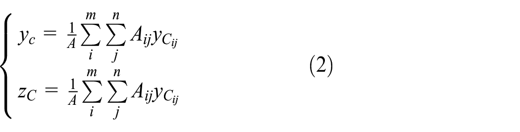
where
For arbitrary cross-sectional shape in Figure 3, the bending moment of inertia

So


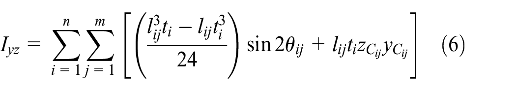
where


Arbitrary cross-sectional shape and its centroid coordinate.
In addition, the torsional moment of inertia can be obtained by solving the following differential equation

where

For thin-walled cross-section, differential equation (9) can be transformed as algebraic equation by using finite element (FE) method. The procedure for calculating the torsional moment of inertia depends on the number of cells. So the torsional moment of inertia of an open section can be written as
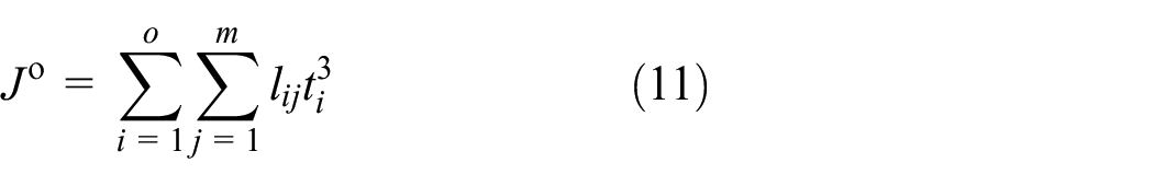
where
The torsional moment inertia of signal-cell section

As shown in Figure 5, the torsional moment inertia of double-cell section
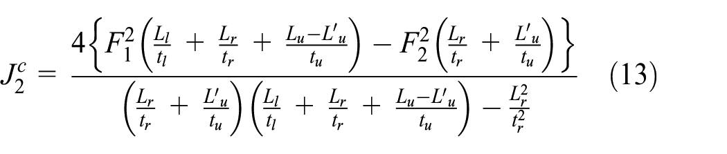
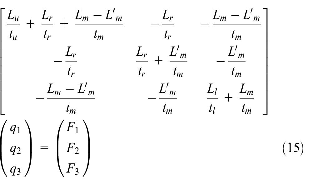
As shown in Figure 6, the torsional moment inertia of three-cell section

where

Single cell.
Double cells.

Three cells.
The torsional moment inertia of four-cell section

where

where

Four cells.
In addition, when a more complex section consists of open and close sections, the torsional moment inertia can be expressed as

where
For rectangular hollow section (RHS) tube, its cross-sectional shape is shown in Figure 8. There are three design variables—breadth, b; height, h; and thickness, t—to describe the RHS. According to the three size design variables, the cross-sectional properties—area, A; bending moments of inertia, Iy and Iz; and torsional moments of inertia, Ix—are then calculated as follows


RHS tube and its centroid coordinate.
It can be seen from equations (20)–(22) that it is more efficient to modify b or h for increasing

Cross-sectional shape of: (a) RHSDC, (b) RHSTC, and (c) RHSQC.
Equivalent stiffness substitution
The bending deformation of tube can be expressed as

where
When conducting the equivalent stiffness substitution, the steel tube and aluminum tube should both sustain the same external load, that is,

Equation (24) can be further rewritten as

Equivalent stiffness substitution indicates

Substituting equations (20) or (21) into equation (26) and only considering the thickness variable t, the thickness ratio between aluminum and steel can be obtained by
where
Likewise, the height ratio between aluminum and steel RHS tubes can be obtained by

Equation (28) indicates that the height of aluminum tube should be 1.7 times as high as steel to meet the equivalent stiffness design. Meanwhile, the aluminum tube is more lightweight than steel tube. Therefore, the substitution of height can achieve the lightweight design.
Equivalent strength substitution
The bending deformation of tube can be expressed as

where
When conducting the equivalent strength substitution, the aluminum tube and steel tube should both sustain the same external load, that is,

Equation (30) can be further rewritten as
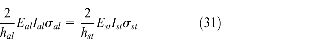
Substituting equations (20) or (21) into equation (31) and only considering the thickness variable t, the thickness ratio between aluminum and steel can be obtained by

where
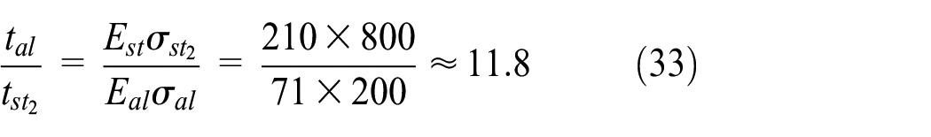
Likewise, the height ratio between aluminum and steel RHS tubes can be obtained by


Then, the height of aluminum tube should be 1.8 times as high as mild steel tube to meet the equivalent strength design. Therefore, the aluminum tube is more lightweight than mild steel tube, and the substitution of height can acquire the lightweight design. On the contrary, it is invalid for high-strength steel tube according to equation (35).
Equivalent substitution criteria of large deformation
As shown in Figure 10, the bending moment
where

Bending mode of thin-walled circular tube.
When the bending moment of two types of tubes are equal and only considering the thickness variable


Then, the thickness of aluminum circular tube should be 1.1 and 1.6 times as thick as mild steel and high-strength steel tubes under the equivalent substitution criteria of large deformation. Therefore, the aluminum circular tube is more lightweight than two types of steel tubes, and the substitution of thickness can achieve the lightweight design.
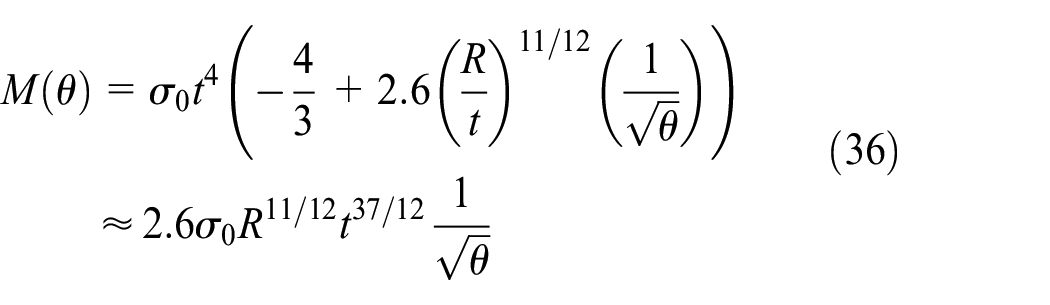
As shown in Figure 11, the mean crushing force

where

Bending mode of thin-walled channel section tube.
When the mean crushing force of two types of tubes are equal and only considering the thickness variable
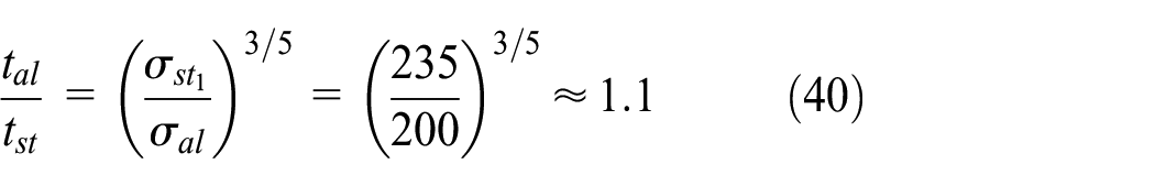
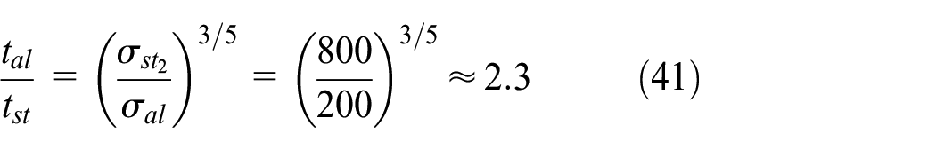
Equations (40) and (41) indicate that the thickness of aluminum channel section tube should be 1.1 and 2.3 times as thick as two types of steel tubes under the equivalent substitution criteria of large deformation. Therefore, the aluminum channel section tube is more lightweight than two types of steel tubes, and the substitution of thickness can achieve the lightweight design.
By tensile test of specimen, as illustrated in Figure 12(a), we obtained the stress–strain curve of aluminum (AA6063), which is shown in Figure 12(b).

(a) Tensile test, and (b) stress–strain curve of AA6063.
As shown in Figure 13, the relationship between the force and deflection can be tested by the three-point bending test,57,58 by which one can measure the bending properties of aluminum tube indirectly.

Schematic diagram of the three-point bending.
As shown in Figure 14(a), the three-point bending of RHS aluminum tube was carried out. Meanwhile, the velocity of indenter was set to be 10 mm/min. The initial cross-sectional shape is shown in Figure 15(a), while Figure 14(b) shows the RHS cross-sectional shape after plastic deformation. Meantime, Figure 14(c) and (d) shows the RHSDC cross-sectional shape and RHSTC cross-sectional shape after plastic deformation, respectively.

(a) Three-point bending test, (b) section configuration of RHS, (c) section configuration of RHSDC, and (d) section configuration of RHSTC.
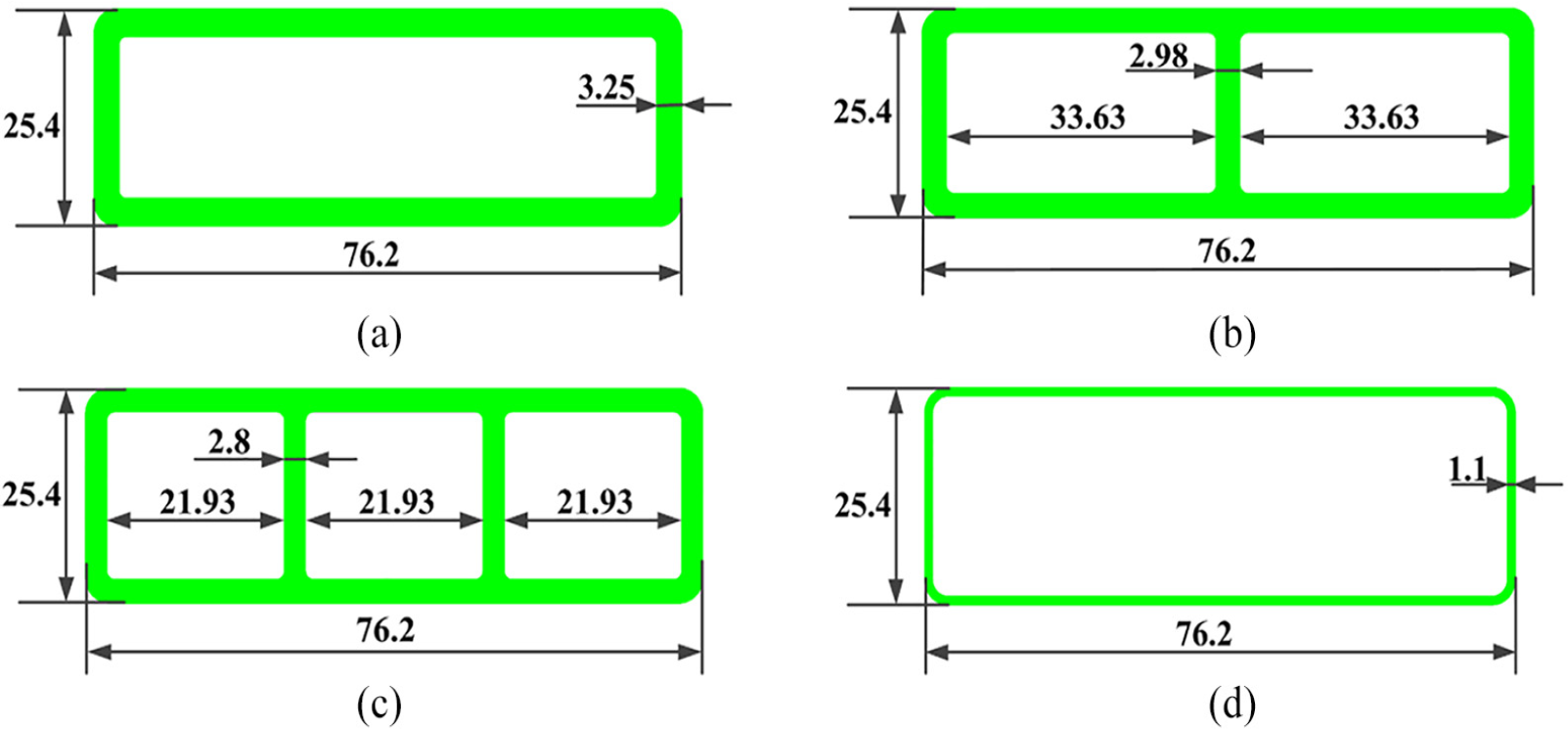
Cross-sectional configurations: (a) RHS aluminum tube, (b) RHSDC aluminum tube, (c) RHSTC aluminum tube, and (d) RHS steel tube.
To contrast with the experiment, the FE analysis is conducted by nonlinear explicit code LS-DYNA, as shown in Figure 16, and solid elements are employed to discretize the aluminum tube. The force–displacement curves of simulation and experiment of aluminum RHS tube are plotted by the solid line and the dot line in Figure 17, respectively. From this figure, the force increases in the early time and then decreases with the indenter moving down. RHS aluminum tube loses stability after the force reaches peak value.

FE model of three-point bending.

Aluminum RHS tube.
It can be seen from Figure 17 that the peak force of RHS aluminum tube of simulation and experiment are 9.762 and 9.862 kN, respectively. The maximum error of peak force is within 1%. There is good consistency between the experimental result and simulation data, so the FE model can well predict the deformation and force response of the tubes under bending mode.
Likewise, aluminum RHSDC and RHSTC tubes are analyzed, and the curves are plotted as shown in Figures 18 and 19. The maximum errors of peak force are within 1% and 7%, respectively. This proves further that there is good consistency between the experimental result and simulation data of aluminum RHSDC and RHSTC tubes, so the FE model can well predict the deformation and force response of the tubes under bending mode.

Aluminum RHSDC tube.

Aluminum RHSTC tube.
In the following, we, respectively, replace the RHS aluminum tube with RHSDC in Figure 15(b) and RHSTC aluminum tube in Figure 15(c) by the way of equal mass substitution. The force–displacement curves are illustrated in Figure 20. The peak force of RHSTC and RHSDC aluminum tubes are 11.988 and 11.214 kN, respectively, which are both larger than that of RHS aluminum tube. Among three types of aluminum tubes, the RHSTC has the strongest ability of bending resistance, followed by RHSDC, and the last RHS aluminum tube.

Force–displacement curves for five types of tubes with equal mass.
Finally, RHS steel tube with equal mass is shown in Figure 15(d). There are two types of steel tubes which made of mild steel and high-strength steel, respectively. According to the curves displayed in Figure 20, it can be concluded that the peak force of mild steel and high-strength steel RHS tube are 2.835 and 6.741 kN, respectively, which are far less than RHS aluminum tube of equal mass. This proves that the bending resistance of RHS aluminum tube obviously exceeds steel tube.
Engineering example
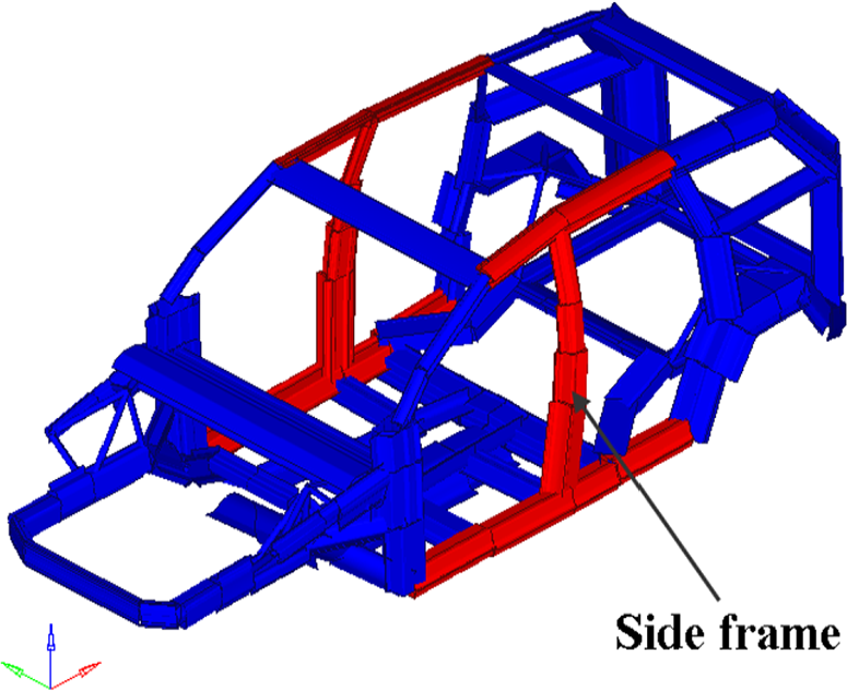
Side frame of automobile structure
As illustrated in Figure 21, side frame of automobile structure can protect the passengers from injury in automobile side impact. Therefore, by using the above theoretical and experimental results, the equivalent mass substitution of aluminum for steel is applied into the side frame to improve its crashworthiness.
Components of Kuga’s frame.
As shown in Figure 22(a), the shell FE model of steel side frame consists of three types of RHS tube. The shape and thickness of components are marked near side frame. Comparatively, aluminum side frame in Figure 23(b) consists of one RHSTC aluminum tube and two RHSDC aluminum tubes. In addition, the two FE models have equal mass.

Side frame of automotive structure: (a) steel, and (b) aluminum.

Marked nodes A, B and C of B-pillar for side frame.
The two FE models are both solved by the commercial software LS-DYNA. The initial velocity of rigid pillar and impact time are, respectively, set to be 8.3 m/s and 0.04 s, which are obtained from the occupant protection regulations for the pole side impact. 59 The displacement and acceleration of these nodes, which are labeled in Figure 23, are plotted in Figures 24–26. Then, Figure 27 shows the deformation of two models and the results are listed in Table 2.

Comparison of (a) displacement and (b) acceleration for Node A.

Comparison of (a) displacement and (b) acceleration for Node B.

Comparison of (a) displacement and (b) acceleration for Node C.

Deformation of side frame: (a) steel, and (b) aluminum.
Comparison of displacement and acceleration responses.

According to Table 2, it can be concluded that the intrusion of three nodes in aluminum side frame is less than that of steel one. So the aluminum side frame can provide bigger living space for passengers in vehicle side crash. Meanwhile, the acceleration of those three nodes in aluminum side frame is far less than steel. So it can effectively decrease the injury of passengers in automobile side impact. Therefore, by using the equivalent substitution criteria of aluminum for steel under the large deformation, the side frame can realize lightweight and crashworthiness design.
Chassis frame of automobile structure
The chassis frame of automobile structure, which consists of two transverse beams and eight longitudinal beams, is used to resist small deformation under bending and torsional conditions. Figure 28 shows the chassis frame with bending and torsional conditions. For transverse beams and longitudinal beams, their cross-sectional sizes, including width, height, and thickness, are uniform, respectively. By using the above equivalent substitution criteria of small deformation, the steel chassis frame is substituted for the equivalent mass aluminum chassis frames with increased thickness and increased height, respectively. The cross-sectional sizes for these three types of chassis frames are listed in Table 3. The material parameters for steel and aluminum are listed in Table 4.

Chassis frame with bending and torsional conditions: (a) bending condition, and (b) torsional condition.
Cross-sectional sizes for various chassis frames.

Material parameters for steel and aluminum.
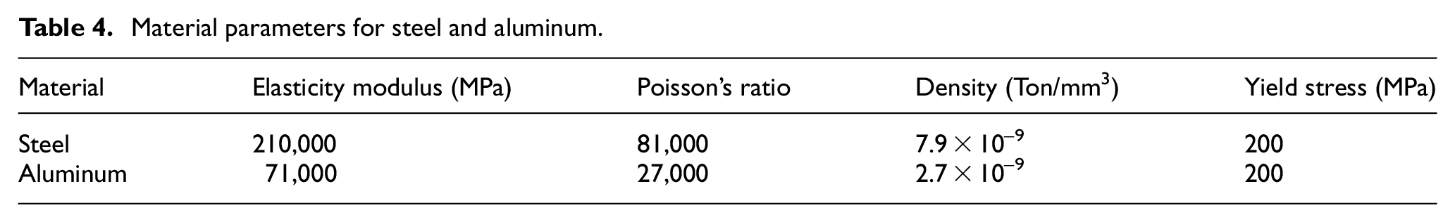
The commercial software OptiStruct is used to solve the stiffness and strength of three chassis frame models. The maximum displacements and stresses of these three models are listed in Table 5. According to Table 5, it can be concluded that (1) for the aluminum chassis frame with the increased thickness under bending and torsional conditions, the maximum displacements are larger than that of the steel one and the maximum stresses are less than that of the steel one. Especially, the steel and aluminum have the same yield stress. So the aluminum chassis frame with the increased thickness cannot improve the stiffness and can improve the strength. (2) For the aluminum chassis frame with the increased height under bending and torsional conditions, the maximum displacements and stresses are less than that of steel one, so the aluminum chassis frame with the increased height can improve the stiffness and strength. Therefore, by using equivalent substitution criteria of aluminum for steel under small deformation, the structure can realize lightweight and improve its stiffness or strength.
Comparison of displacement and stress for various chassis frames.

Conclusion
Equivalently structural substitution of aluminum for steel under bending mode is researched by considering small and large deformation. The following conclusions can be summarized from this study:
Formulations of cross-sectional properties, including open, single-cell, double-cell, three-cell, and four-cell cross-sections were derived to evaluate the stiffness of thin-walled beam.
In the case of small deformation, equivalent stiffness design and equivalent strength design are both considered. In terms of equivalent stiffness design, only the substitution of aluminum tube’s thickness cannot acquire the lightweight design. The substitution of aluminum tube’s height can achieve the goal but demands more design space. In terms of equivalent strength design, the substitution of aluminum tube’s thickness cannot acquire the lightweight design, compared with two types of steel: mild steel and high-strength steel. But it is effective for the substitution of aluminum tube’s height, compared with mild steel tube. At the same time, it has no effect on high-strength steel tube.
In the case of large deformation, the steel thin-walled circular tube and thin-walled channel tube are substituted by aluminum tube under equivalent stiffness. Then compared with steel tubes considering crashworthiness under equal mass, aluminum tubes with multi-cell configurations have a great advantage in the aspect of resisting bending. Among those tubes, the RHSTC aluminum tube has the strongest ability of bending resistance.
Finally, the side frame example verified that aluminum model has better ability to resist large deformation and can improve crashworthiness. The chassis frame example verified that by increasing the height, the aluminum model can improve strength and stiffness, but by increasing the thickness, the aluminum model can improve strength and cannot improve stiffness. This study can provide effective guidance to develop high performances and lightweight of aluminum structure. Meanwhile, the proposed method is universal and can also be applied in aerospace structures.
Footnotes
Appendix 1
In addition, the centroid coordinates of rectangular hollow section with double-cell (RHSDC) cross-section z and y can be calculated as
The bending moment of inertia
The torsional moment of inertia
Appendix 2
In addition, the centroid coordinates of rectangular hollow section with triple-cell (RHSTC) cross-section z and y can be calculated as
The bending moment of inertia
The torsional moment of inertia
Appendix 3
In addition, the centroid coordinates of rectangular hollow section with quadruple-cell (RHSQC) cross-section z and y can be calculated as
The bending moment of inertia
The torsional moment of inertia
Handling Editor: James Baldwin
Declaration of conflicting interests
The author(s) declared no potential conflicts of interest with respect to the research, authorship, and/or publication of this article.
Funding
The author(s) disclosed receipt of the following financial support for the research, authorship, and/or publication of this article: This work was supported by the Science and Technology Research Project of Education Department of Jilin Province (grant number JJKH20190013KJ).