
Abstract
Meshing power loss is one of the most important parts in power loss calculation of planetary gear set. However, most of the conventional methods assumed the friction coefficient between gears as a constant value in the meshing power loss calculation, and most importantly, the influence of gear tooth surface geometry is usually ignored, for example, roughness. Therefore, a new meshing power loss calculation model for planetary gear set that considers tooth surface roughness is proposed on the basis of elasto-hydrodynamic lubrication method. With the proposed model, a planetary gear set dynamic model that considers friction force between gears is first established to study the time-varying meshing forces, sliding speeds, and curvature radii of the gear pairs. Then, an elasto-hydrodynamic lubrication model of the gear pair contact interface is constructed to investigate and modify the friction force distribution in the gear meshing process of the dynamic model iteratively until the meshing forces converge to stable values. Furthermore, the relationship between the tooth surface roughness and film thickness is studied in the elasto-hydrodynamic lubrication model. After that, the meshing power loss is calculated based on the obtained meshing forces, friction coefficients, sliding speeds, and so on. The results show that there is a sudden growth of the meshing power loss at the end of the meshing cycle, which has a good agreement with the meshing force impact. And, it is found that tooth surface roughness has a direct influence on the meshing power loss of sun–planet gear pair, which yields an increasing tendency as the surface roughness growing.
Introduction
Due to the requirement of reducing carbon emissions and environmental issues, machine efficiency improvement has become a critical research topic in the past decades. Planetary gearbox is one kind of popular transmissions in machinery, which has been widely used in aerospace, wind turbine, automobile, helicopter, and so on.1–5 Therefore, it is of significance to investigate the main factors of power loss in planetary gearbox to help improve its efficiency.
Oil churning, gear meshing, and bearing rotating are the main reasons of the power loss in planetary gearbox. 6 Among these power loss reasons, gear meshing is one of the most important parts in power loss, and it has a close relationship with the meshing force, friction coefficient, rolling speed, and skidding speed.7–9 Thus, the power loss calculation method of gear meshing has attracted lots of attention. For instance, Marques et al. 10 established a simplified gear dynamic model for spur and helical gear system, and gear meshing power losses for different gear geometries at different operating conditions are studied based on two distinct coefficients of friction formulations. Baglioni et al. 11 investigated the influence of the addendum modification on spur gear efficiency, and two kinds of friction coefficient calculation methods are analyzed and compared in their study, and it is found that the differences in terms of efficiency using a global mean friction coefficient or a local friction coefficient are around 0.5%. Diez-Ibarbia et al. 12 proposed a frictional power loss calculation method on spur gears with tip reliefs; sliding friction between teeth in presence of lubricant was studied based on Coulomb’s model, and the results show that tip relief improves the efficiency of the system due to the reduction of effective contact ratio. Nutakor et al. 13 developed a composite power loss model combining a non-uniform load distribution model with a local friction coefficient at any point of contact, and a sensitivity study was carried out to examine how the design parameters of planetary gear sets and bearings and lubricant properties influence performance. Above all, the state-of-the-art studies mainly focus on parallel axis gear systems, and most of the teeth meshing surfaces are supposed as smooth. However, it is known that the manufactured tooth surface are indeed not smooth, which has a significant influence on the film distribution between meshing teeth. Furthermore, the tooth surface roughness has a dynamic influence on lubrication conditions between in the meshing cycle, that is, friction coefficient, sliding speed, and contact radius between teeth will change dynamically.
Therefore, elasto-hydrodynamic lubrication (EHL) model is employed to investigate the lubrication condition and friction characteristics between gear teeth in this article. EHL and EHL-based methods are widely used to study the lubrication condition at the contact area. For instance, Li 14 constructed a coupled model of a 6-DOF (degree-of-freedom) motion equation set and the thermal mixed EHL governing equations to predict the mechanical power loss under the condition where the gear dynamics and tribology disciplines interact. Liu et al. 15 proposed a thermal starved EHL model to study the effect of starved lubrication on the contact performance of a spur gear pair. Talbot et al. 16 presented an experimental study on power losses of planetary gear sets, and the test matrix consisted of gear sets having three to six planets under loaded and unloaded conditions in order to separate load independent (spin) and load-dependent (mechanical) power losses. Ziegltrum et al. 17 developed a transient elasto-hydrodynamic lubrication (TEHL) simulation model based on a finite element formulation to study the TEHL contact along the path of contact of spur gears with a focus on load-dependent gear loss of different lubricants, and the simulated result has a good agreement with the measured load-dependent gear power losses in the Gear Research Centre (FZG) experimental bench when taking mixed lubrication into account. Marques et al. 18 introduced some gear load sharing models for spur and helical gears with the elastic and frictional effects taken into consideration to do more refined estimations of gear friction losses, and the results indicated that elastic effects indeed have some influence on gear power loss. Martins et al. 19 investigated the influence of oil formulation on the protection against gear micropitting and also its influence on gear efficiency, and the results showed that the base oil, the additive package, as well as their combination have a significant influence on the efficiency and micropitting performance. Fatourehchi et al. 20 studied the effect of tooth crowning and tip relief on system efficiency; the proposed method included an analytical elasto-hydrodynamic analysis of elliptical point contact of crowned spur gear teeth, and the results show that better surface finish with both crowning and tip relief modifications reduces the gear contact power loss. Nutakor et al. 13 developed a composite power loss model combining a non-uniform load distribution model with a local friction coefficient at any point of contact and oil drag formulations, and the influence of design parameters of planetary gear sets and bearings and lubricant properties on power loss performance were investigated.
In summary, there exist many literatures on mechanical power loss of parallel axis gear systems through a modeling or experimental method, as well as the influence of design parameters and lubrication parameters on power loss. However, there is no efficient mechanical power loss calculation method that considers surface roughness of tooth surface in the planetary gear set. Furthermore, the relationships between tooth surface geometry, lubrication condition, friction characteristics, and power loss performance have not been investigated in the existing the literature works. In order to settle this problem, a new meshing power loss calculation method is proposed in this article. The time-varying meshing forces, sliding speeds, and curvature radii of the gear pairs are first calculated based on a newly established dynamic model of planetary gear set considering EHL. An EHL model is established to study the dynamic lubrication condition of the tooth pair in the meshing cycle, and the friction force distribution is then iteratively calculated when the meshing force becomes stable. Finally, the meshing power loss is obtained based on the calculated parameters of the proposed method, for example, sliding speed, friction force, and rolling force.
The rest of the article is organized as follows. The influence of elastic deformation and lubrication on meshing power loss calculation is explained in section “Problem formulation.” Section “Meshing power loss calculation of planetary gear set” introduces the proposed meshing power loss calculation method. The result and discussion are given in section “Result and discussion.” Finally, concluding remarks are drawn in section “Conclusion.”
Problem formulation
Efficiency is one of the important indexes in the assessment of a planetary gear set. A power loss calculation model with higher computational accuracy is necessary in the evaluation of efficiency. However, tooth surface roughness, elastic deformation, and lubrication conditions are usually ignored in the conventional power loss calculation methods for planetary gear set. Figure 1 illustrates the contact characteristics and elastic deformation of planetary gear set during gear meshing—where fs1, fs2, fp1, and fp2 represent the friction forces of sun-planet gear tooth pair; δθs, δθp, and δθr represent the deformation rotating angles of sun gear, planet gear, and ring; and ωs, ωc, and ωp are the rotating speeds of sun gear, planet gear, and ring, respectively. It is shown that the tooth surface roughness and deformation have a direct influence on the oil film parameters, such as contact curvature radius, which will further affect the friction forces, sliding speeds, and so on. For example, the curvature radius of the contact area of the gear pair will change due to the elastic deformation, which can be rewritten as

where ρ1 and ρ2 are the ideal curvature radii of the driving gear and driven gear, respectively. δz, δf, and δh are the elastic deformations along action line of gear tooth, gear base, and Hertz contact, respectively. Besides, the rotation angle between the actual meshing point and the vertical line of the meshing line is affected, which will yields a changed sliding speeds between the gear pair in turn. The rotation angle can be obtained as

where rb1 and rb2 are the base circle radii of the gear pair, respectively. α1 and α2 are the rotation angles between the theoretical meshing point and the vertical line of the meshing line of the gear pair.
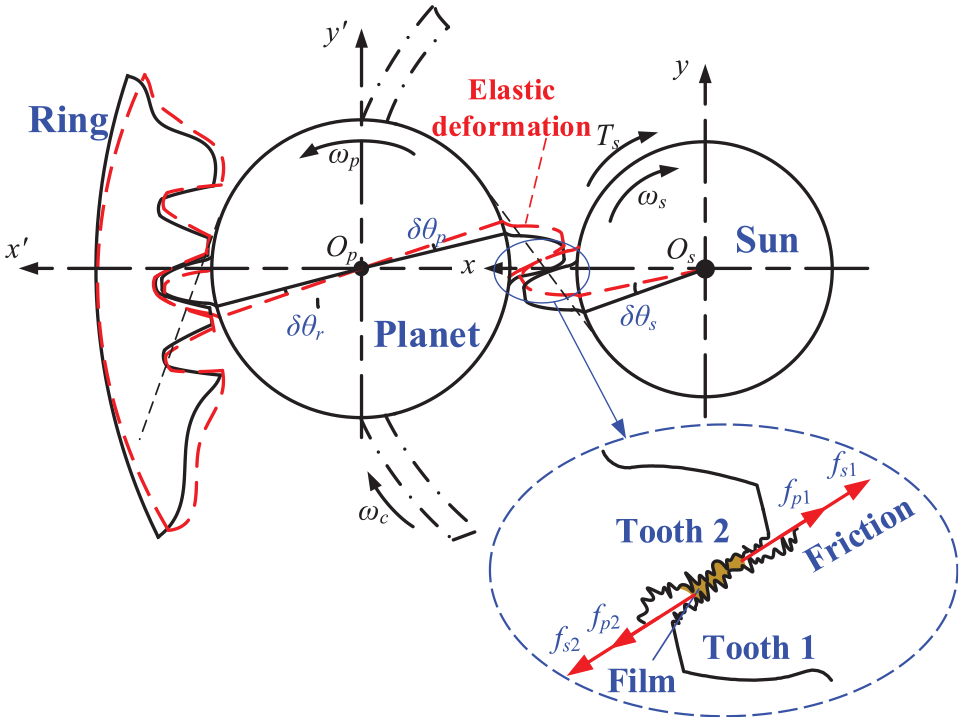
Problem formulation in power loss calculation of planetary gear set.
Furthermore, the tooth surface roughness yields a time-varying film thickness, as shown in Figure 2, which is usually neglected in the above-mentioned methods.
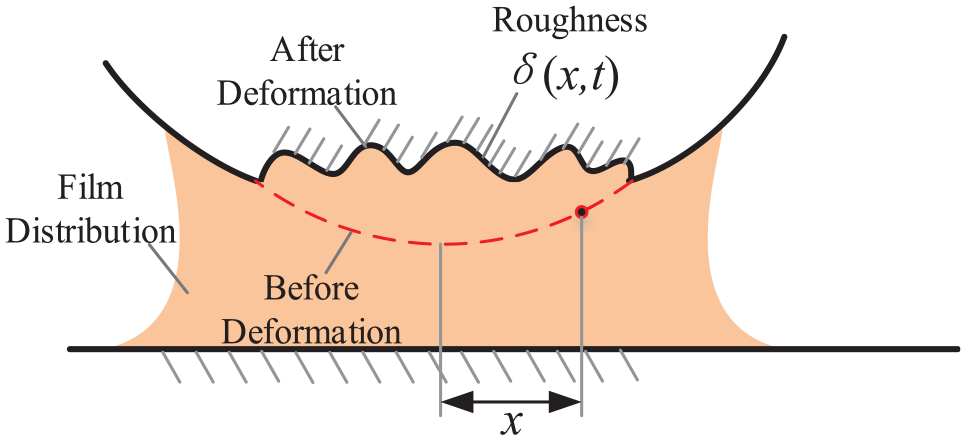
Effect of tooth surface roughness on film thickness.
Aiming to obtain a more accurate meshing power loss, a new meshing power loss calculation model of a planetary gear set that considers elastic deformation, tooth surface roughness, and lubrication conditions is established in this article.
Meshing power loss calculation of planetary gear set
Figure 3 illustrates the overall process of the meshing power loss calculation of planetary gear set. There exist three main steps in the proposed algorithm; first, the dynamic model of the planetary gear set that considers friction force on the tooth surface is presented and established, and the input boundary parameters and the initialized friction coefficients are substituted into the dynamic model to obtain the meshing force, contact radius, sliding speed, and so on. After that, an EHL model of the gear pair contact interface is constructed to investigate the friction force distribution in the gear meshing process, and the effect of the roughness of the gear surface is also studied in this step, which is described by fractal geometry and its two-dimensional (2D) surface profile height according to the Weierstrass–Mandelbrot (W-M) function due to the properties of continuity, non-differentiability, scale invariance, and self-affinity.21–23 The 2D surface profile height can be obtained by the W-M function

where Ra represents the root mean square roughness of tooth surface; ω stands for the spatial frequency of the profile; ωL and ωU are the starting frequency and the upper limit of frequency, respectively; and D represents the fractal dimension. All these parameters can be obtained in Qin et al. 22 Thus, the relationship between the statistical values of roughness and fractal geometry profile is established.
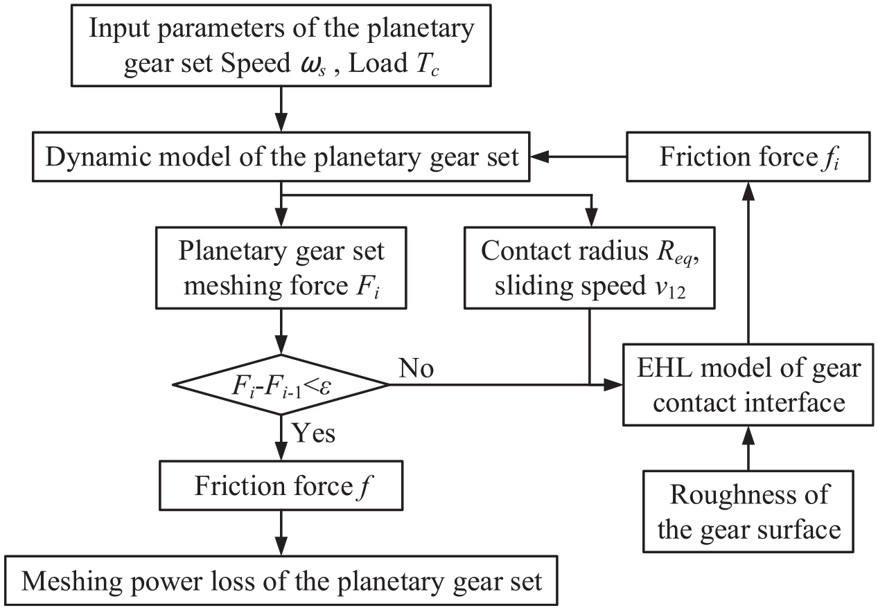
Overall process of the meshing power loss calculation of planetary gear set.
Finally, because there are two meshing types in the planetary gear set: external and internal meshing, the meshing power loss calculation method is also discussed based on the two meshing types, and the meshing force, friction force, contact radius, and sliding speed of the gear pair obtained in step 1 and step 2 are applied to derive the meshing power loss.
Dynamic model of planetary gear set considering friction
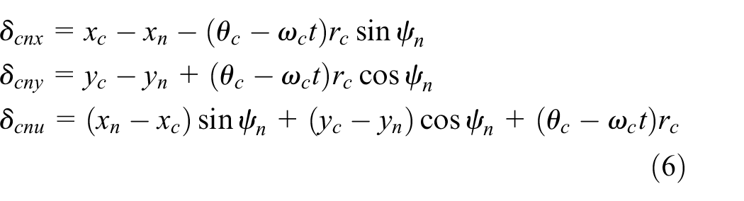
Aiming to obtain the boundary conditions for EHL model, such as meshing forces and speeds between gears, the dynamic model of planetary gear set that considers friction is established in this section, which consists of one sun gear (s), one carrier (c), one ring (r), and N planets (p) with the rotational motion of the ring gear constrained,24–26 as illustrated in Figure 4. Each element has 3 DOFs with one rotation uj and two translations xj, yi (j = c, r, s, 1, 2, …, N). The total number of DOFs is 3(N + 3). Bearings are considered as linear springs. Without loss of generality, kjx and cjx are set equal to kjy and cjy, respectively. ksn and krn refer to the gear meshing stiffness of sun–planet and planet–ring gear pairs, respectively. esn and ern represent the transmission errors of sun–planet and planet–ring gear pairs, respectively. kjt and cjt represent the rotating stiffness and damping. fsn and frn denote the friction forces of sun–planet and planet–ring gear pairs, respectively. Hsn and Hrn are the corresponding friction arms of fsn and frn, respectively. θj refers to the rotation angle of each component in planetary gear set. The relative displacements along the lines of action of sun–planet and planet–ring gear pairs can be expressed as

where

Dynamic model of the one-stage planetary gear set.
By applying the Lagrange formulation, the global equation of the motion of the planetary gear set that considers friction can be obtained. The motion equation of carrier, ring, sun gear, and the nth planet can be written as


where mj represents the component’s mass, ksn/krn and csn/crn can be calculated based on analytical method according to Liang et al. 27 λ stands for the direction of friction, and it is equal to 1/−1 before/after the meshing point passes through pitch point, and it is equal to 0 when the meshing point coincides with the pitch point.
EHL model of gear contact interface
In the gear meshing process of planetary gear set, there is a non-Newtonian fluid flow in the contact areas of the gear pairs, which is governed by the transient Reynolds equation

where ρ, p, and h represent the density, pressure, and thickness of the fluid at coordinate x in the direction of rolling at time t, respectively. ur represents the rolling speed, and it can be obtained as ur = 1/2(vg1(t) + vg2(t)), where vg1 and vg2 refer to the rolling speeds of gear 1 and gear 2, respectively. η* denotes the equivalent viscosity of the fluid, which can be obtained based on Ree–Eyring model28,29

where τ0 and τm denote the lubricant’s reference shear stress and the viscous shear stress, respectively. η refers to the viscosity of the fluid.
Because the EHL model mainly focuses on the contact area of the gear pair, a simple equivalent model is proposed to describe the contact area of the gear pair before the calculation of the fluid thickness, as shown in Figure 5.

Gear equivalent contact model.
In the figure, K is the meshing point of pinion and gear.

where μ1 and μ2 are Poisson’s ratio of the gear pair. Thus, the film thickness and elastic deformation relationship can be obtained, as illustrated in Figure 6. There are four parts in the film thickness: reference film thickness h0(t), the unloaded geometric gap between two tooth surfaces g0(x, t), the elastic deformation v(x, t), and the geometric gap caused by tooth surface roughness δ(x, t).

Film thickness and elastic deformation relationship.
The EHL film thickness can be calculated as


And, the elastic deformation can be obtained based on discrete convolution–fast Fourier transform (DC-FFT) method30,31

where ξ is the additional coordinate at coordinate x. ξs and ξe are the limits of the computational domain of the contact zone.
As known, the fluid viscosity will increase with the growth of pressure, and a two-slope viscosity–pressure model of Allen et al. 32 is applied in this article

where γ1 and γ2 are the viscosity–pressure coefficients for the low (p < pa) and high (p > pb) pressure ranges, respectively. c0, c1, c2, and c3 are determined by the continuity constraint of η and dη/dp. pt is the transition pressure value between pa and pb. Furthermore, the density–pressure relationship is obtained based on Dowson–Higginson model 33

Besides, because the numerical solution of the EHL problem is performed under a given load condition, a balance equation of the film pressure and load is needed to check whether the solution is right or not. The line contact load balance equation is given as

where Ω denotes the contact area. Then, the numerical solutions of the above EHL equations are calculated based on Thomas et al.’s 34 model.
Meshing power loss calculation
Based on sections “Dynamic model of planetary gear set considering friction” and “EHL model of gear contact interface,” the time-varying meshing forces and friction coefficients of planetary gear set can be calculated. Furthermore, the instantaneous meshing power loss function of planetary gear set is obtained

where
The external and internal meshing types exist simultaneously in planetary gear set, and the meshing relationship of the two types is illustrated in Figure 7.

The meshing relationship of (a) external and (b) internal meshing types in planetary gear set.
In the figure, rbx denotes the radius of the base circle, αx refers to the rotating angle, K is the meshing point, ρx denotes the equivalent radius at the meshing point K, M1M2 is the friction direction at meshing point K, and x = 1, 2. Thus, the relative sliding speed between gear 1 and gear 2 can be obtained

Because the planet gears are not only rotating around their own centers but they are also rotating around the sun gear center with the planet carrier, vsp and vpr can be obtained based on equation (12)


where ωs, ωc, ωp, and ωr represent the rotating speeds of sun gear, carrier, planet gear, and ring, respectively. Because the ring is set as standstill, ωr = 0. It is noted that the above parameters are calculated with the consideration of elastic deformation.
Result and discussion
The detail simulation parameters of the planetary gear set and the lubrication conditions are listed in Tables 1 and 2; sun gear is taken as the input, and the input speed and load are set to 1000 r/min and 800 N m, respectively, as an example. And, the dynamic and kinetic viscosities in other temperatures can be obtained based on Table 2 by linear interpolation algorithm. The roughness of the tooth surface Ra is set to 0.1 as an example for study.
Detail parameters of the planetary gear set.

Detail parameters of the lubrication conditions.

The calculated meshing stiffness and meshing force of the sun–planet and ring–planet gear pairs are illustrated in Figures 8 and 9, respectively. The meshing stiffness of sun–planet gear pairs fluctuate from 6.6 × 10⁸ to 1.2 × 10⁹ N/m, and the meshing stiffness of ring–planet gear pairs fluctuate from 1.2 × 10⁹ to 2.1 × 10⁹ N/m, as shown in Figure 8. The corresponding meshing forces are illustrated in Figure 9, and it is found the meshing forces of sun–gear pairs fluctuate from 1826 to 4859 N and the meshing forces of ring-gear pairs fluctuate from 1844 to 4256 N, respectively. Besides, it is found that there is a sudden shock of the meshing forces when the meshing cycle goes into single tooth zone or double tooth zone in both sun–planet gear pairs and ring–planet gear pairs. And, the impulsive shocks generated when the meshing cycle goes into double tooth zone from single tooth zone is larger than the shocks generated when the meshing cycle goes into single tooth zone for the sun–gear pairs, which means there is a large mesh impact.
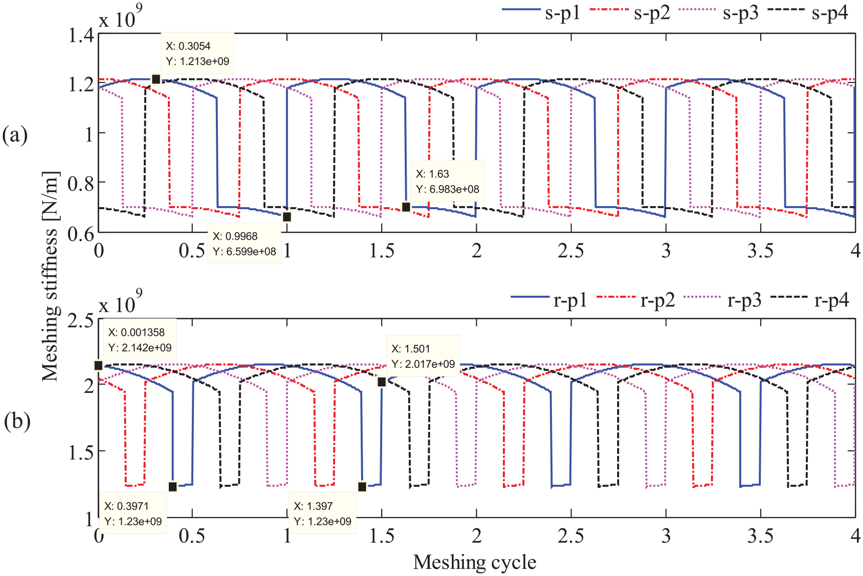
The meshing stiffness of (a) sun–planet gear pairs and (b) ring–planet gear pairs.
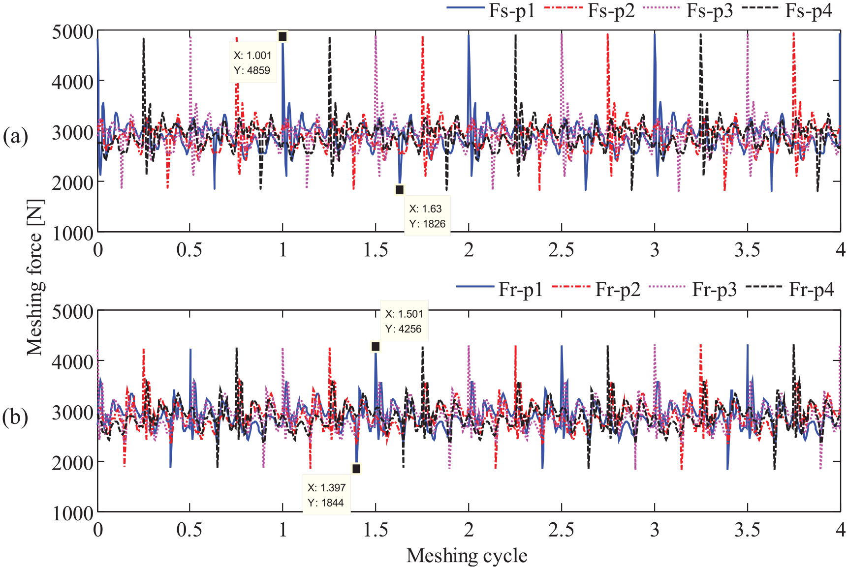
The meshing force of (a) sun–planet gear pairs and (b) ring–planet gear pairs.
The lubrication film thicknesses and pressures of the sun–planet gear pair and ring–planet gear pair at pitch circle are illustrated in Figure 10(a) and (b), respectively, and the smooth gear tooth surface is also calculated for comparison, where the red solid line and dashed line represent the oil film pressure distributions with and without the surface roughness taken into consideration, respectively. And, the blue solid line and dashed line represent the oil film thicknesses with and without the surface roughness taken into consideration, respectively. As predicted in section “Problem formulation,” the tooth surface roughness has a direct influence on film thickness and film pressure. There are some obvious fluctuations in the film thickness and pressure caused by surface roughness in both sun–planet gear pair and ring–planet gear pair. In general, the film pressure of the sun–planet gear pair is higher than the ring–planet gear pair, and the maximum film pressures in sun–planet and ring–planet gear pairs are 2.23 × 10⁸ and 1.567 × 10⁸ Pa, respectively. And, the sun–planet gear pair yields higher fluctuations in terms of film pressure and thickness than ring–planet gear pair, which may be due to the different meshing forces of sun–planet gear pair and ring–planet gear pair, as demonstrated in Figure 9, namely, the oil film of the sun–planet gear pair withstand higher load than the ring–planet gear pair at pitch circle.

Film thicknesses and pressures of (a) sun–planet gear pair and (b) ring–planet gear pair at pitch circle.
The first meshing cycle of the sun–planet 1 and ring–planet 1 is taken as an example to calculate the sliding friction and the meshing power loss. The friction coefficients of the sun–planet and ring–planet gear pairs are shown in Figure 11. The ring–planet gear pair yields a higher friction coefficient than the sun–planet gear pair with the highest friction coefficient almost equal to 0.05, which may be due to the higher relative sliding speed. Besides, both the sun–planet and ring–planet gear pairs achieve higher friction coefficients when taking the surface roughness into consideration. In addition, there is a sudden drop of the ring–planet friction coefficients when the meshing cycle goes into single tooth zone, which may be due to the sudden change of gear meshing stiffness, as shown in Figure 8.
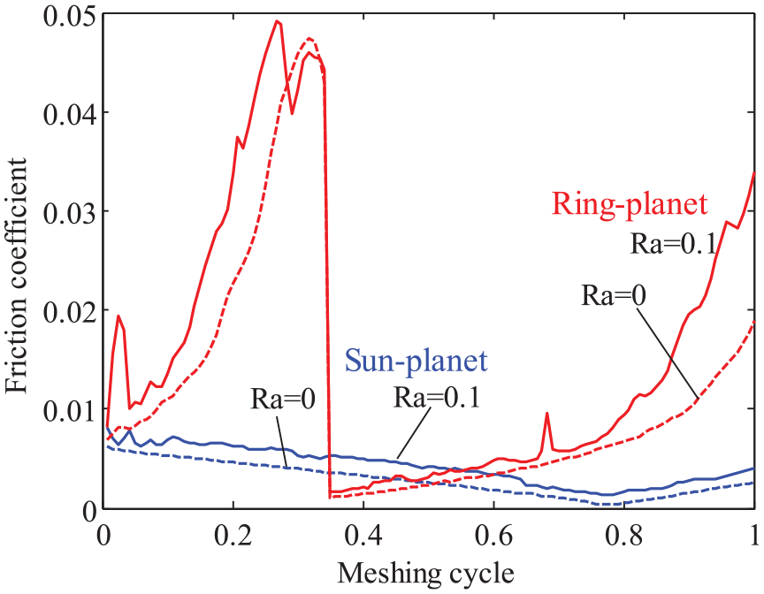
Friction coefficients of the sun–planet and ring–planet gear pairs.
Figure 12 illustrates the meshing power losses of the sun–planet and ring–planet gear pairs. The proposed method with roughness and elastic deformation, the proposed method with smooth surface and elastic deformation, the conventional method without EHL, and the conventional method without elastic deformation are compared. It is found that the proposed method with the roughness and deformation taken into consideration yields a higher power loss than that of other methods when the meshing cycle goes into single tooth zone or double tooth zone. And, this phenomenon is in agreement with the mesh impact of gear pair at the moment of single and double tooth alternation. The conventional method without EHL taken into account achieves lowest power loss, which is because the friction coefficient remains a constant value in the whole meshing cycle. The power loss curves for the conventional method without elastic deformation taking into consideration are smooth, and this is because the meshing forces are smooth when there is no elastic deformation of the gear tooth. Above all, conclusion can be drawn that the proposed method taking roughness and elastic deformation into consideration can predict the meshing power loss for planetary gear set with a higher accuracy, especially in the prediction of the sudden growth of the power loss at the moment when single and double teeth alternate.

Meshing power losses of (a) sun–planet and (b) ring–planet gear pairs.
In order to investigate the effect of tooth surface roughness on meshing power loss of planetary gear set, four kinds of tooth surface roughness with Ra ranges from 0.1 to 0.4, three kinds of input speed with 1000, 1200, and 1400 r/min, and three kinds of input torque with 600, 800, and 1000 N m are calculated for study. Furthermore, the ratio of the maximum instantaneous meshing power loss and the input power (RMIP) is applied to illustrate both the influence of tooth surface and working conditions, and the RMIP can be obtained as

where Pmi denotes the maximum instantaneous meshing power loss in one meshing cycle, Pin refers to the input power, and n and Tin represent the input speed and input torque, respectively.
The effects of tooth surface roughness on RMIP in different working conditions are shown in Figure 13. It can be obviously found that the RMIP values of both sun–planet and ring–planet gear pairs yield increasing trend with the growth of surface roughness, which has a good agreement with the research results in Fatourehchi et al. 20 And, the reason for this phenomenon relies on that the oil film is more easily broken as the roughness increases. The RMIP values has a maximum 3.187‰, 3.170‰, and 2.707‰ increments of the sun–planet gear pair as the roughness increasing from 0.1 to 0.4 at 1000, 1200, and 1400 r/min, respectively. And, the RMIP values has a maximum 3.191‰, 1.932‰, and 3.075‰ increments of the ring–planet gear pair as the roughness increasing from 0.1 to 0.4 at 1000, 1200, and 1400 r/min, respectively. In the working condition of 1000 r/min and 1000 N m, the RMIP values of sun–planet and ring–planet gear pairs reach the maximum values of 3.892‰ and 5.241‰, respectively. Furthermore, the ring–planet gear pair achieves higher RMIP values than the sun–planet gear pair. Besides, the RMIP increases as the input torque increases in both the sun–planet and ring–planet gear pairs. In addition, the input speed has a smaller effect on RMIP than the input torque.

Effect of tooth surface roughness on RMIP: (a) with 1000 r/min of sun–planet, (b) with 1000 r/min of ring–planet, (c) with 1200 r/min of sun–planet, (d) with 1200 r/min of ring–planet, (e) with 1400 r/min of sun–planet, and (f) with 1400 r/min of ring–planet (“Blue” for 600 N m, “Green” for 800 N m, and “Red” for 1000 N m).
Conclusion
This article presents a new meshing power loss calculation model for planetary gear set with the EHL taken into account, based on which the effect of tooth surface roughness is further studied. In the proposed model, a planetary gear set dynamic model—that considers friction force—is first established to investigate the dynamic responses and offers boundary conditions for the constructed EHL model of gear pair contact interface. Finally, the meshing power loss is calculated based on the obtained results from dynamic model and EHL model. The results show the following:
There is a sudden increment or decrement of the meshing stiffness and meshing forces in the beginning or the ending of one gear mesh in both sun–planet and ring–planet gear pairs, and the meshing force tends to yield a larger impulsive shock in the beginning of a double tooth mesh.
Gear tooth surface roughness has a direct influence on lubrication film pressure and thickness, and some secondary peaks occur in both the film pressure and thickness due to the roughness; sun–planet gear pair yields a higher film pressure than ring–planet gear pair at the pitch circle because the different meshing forces.
The proposed method that taking roughness and elastic deformation into consideration yields a large increment of the meshing power loss when single teeth and double teeth alternate, which has a good agreement with the mesh impact of the gear pair at the moment of single and double tooth alternation.
The surface roughness has a direct effect on the maximum instantaneous meshing power loss, with a maximum 3.187‰ and 3.191‰ increments of the sun–planet and ring–planet gear pairs as the roughness increases from 0.1 to 0.4 in the discussed working conditions.
The RMIP values of sun–planet and ring–planet gear pairs reach the maximum values of 3.892‰ and 5.241‰ in the discussed working conditions, and the ring–planet gear pair achieves higher RMIP values than the sun–planet gear pair in most of the situations.
Footnotes
Handling Editor: Anand Thite
Declaration of conflicting interests
The author(s) declared no potential conflicts of interest with respect to the research, authorship, and/or publication of this article.
Funding
The author(s) disclosed receipt of the following financial support for the research, authorship, and/or publication of this article: The authors are grateful for the financial support provided by the National Natural Science Foundation of China (grant nos 51475053 and 51705052) and the China Postdoctoral Science Foundation (grant no. 2019M653335).