
Abstract
This article reports a conceptual study of a new micro-electromechanical power system using elastic leaf piston rotating engine rather than conventional engines as the main component. The proposed innovative elastic rotating micro-electromechanical power system adopts two leaf pistons to substitute the traditional rigid piston for establishing elastic combustors and operates with a novel Humphrey thermodynamic cycle, which brings about high power density and energy conversion efficiency. The motion model of leaf piston is carried out by using the Euler–Bernoulli theory, and a novel calculation method of trial and error is presented to iteratively simulate the motion of elastic piston. The effects of the piston length and installation position on the combustor variation are also investigated. Results indicate that the contact point of piston and cylinder is not the piston end and keeps moving, and the combustor is periodically compressed and expanded by the rotor and piston motion to perform the intake, compression, expansion, and exhaust. Besides, the minimum combustor volume lasts an amount of time, which provides a possible realization of full isovolumetric combustion. A larger installation phase angle of pistons means a longer compression and expansion, larger combustor volume and shorter constant-volume duration.
Introduction
In recent years, there is a growing trend in the miniaturization of mechanical and electromechanical engineering devices, which followed the path about microelectronics, biomechanics, and molecular biology, that was tremendous account of the progress of micro-fabrication techniques. 1 The development of micro-electromechanical system (MEMS) technologies also speeds up the microminiaturization of power system. Based on multiple macro engine prototypes, a variety of micro-electromechanical power systems (MEPSs) are presented, which commonly transform the chemical energy of fuel into mechanical energy or electrical energy, thus providing the power for various micro aircraft, automatic robot, portable computer, wireless electronic device and almost all domains.2–4
Honeywell Company and University of Minnesota presented a concept of micro free-piston engine MEPS, aiming to develop a micro power system sources that contained 10 W/c. 5 Aichlmayr et al. 6 developed the model of micro free-piston engine MEPS first, which has a power of about 10 W, and calculated and analyzed the gist of choosing reasonable parameter of the prototype. Specifically, the micro-scale power generation owns more opportunities to realize high density of hydrocarbon fuels. As an underlying power device, the free-piston engine MEPS gains great superiority, including simple construction with one moving part, and possesses the capability to optimize steady-state combustion along with variable compression ratio. 7 The main challenge with such engine MEPS is the control of the piston motion, and this has not yet been fully resolved for all types of free-piston engine MEPS.
The rotary engine is an ideal power device because it can directly convert energy into driving power without transmission mechanism. Especially, the Wankel rotary engine has been successfully applied to the automobile industry. Under this background, Fu et al. 8 at Berkeley University of California designed a Wankel rotary engine MEPS capable of delivering power on the order of milli-watts. The MEPS was simply arranged for the fabrication techniques developed in the integrated chip community and refined by the MEMS field which embraces the well features such as planar construction, high specific power, and self-valving operation. It used an epitrochoidal-shaped housing less than 1 mm3 in size and has a rotor swept volume of 0.08 mm3. Moreover, the data from Beijing Institute of Technology showed that the minimum cylinder volume of rotary engine based on present technology is 0.1 cm3,9 and presented the different cylinder volumes, which range from 0.348 to 5 cm3, and the output power was 3.8–805 W and the engine speed was 9300–17,000 r/min.
Some MEPSs using micro turbine as power source were also developed rapidly as a promising technology for distributed power generation due to their compact size, low emissions, low maintenance, low noise, high reliability, and multi-fuel capability. 10 The Gas Turbine Laboratory and Microsystems Technology Laboratories of Massachusetts Institute of Technology fabricated a turbine MEPS capable of delivering 10–50 W of power in a combustor, the volume of which was less than 1 cm3, and the fuel consumption is about 7 g in 1 h. Besides, the turbine MEPS with hydrogen fuel operates with a peak gas temperatures of 1800 K, and the combustion efficiency is greater than 90%. The power density of the turbine MEPS is over 1100 MW/m3. 11 Similarly, Spearing and Chen 12 designed a turbine-generator MEPS which can produce 50 W of electrical power. The package of the MEPS is less than 1 cm3 in volume, and the silicon is the main material to form the MEPS structure. Savoulides et al. 13 also introduced an MEPS which uses a micro turbine as power source. The speed of turbocharger can reach 480,000 r/min, and the pressure ratio is 1.21 of compressor to produce about 5 W of power.
Bardaweel et al. 14 presented an external combustion MEPS of cavity encapsulated between two membranes, and the working cycle is nearly rectangular in shape and consists of two constant-temperature processes and two constant-volume processes. Cheng et al. 15 introduced a novel and an efficient non-ideal adiabatic theoretical model for beta-type Stirling engine MEPS and its power could reach 300 W. Nakajima et al. 16 also designed a Stirling engine MEPS with a smaller than a few cubic centimeters, and this engine has about 0.05 cm3/sup/ in a piston swept volume so that the power release is about 10 mW for 10 Hz vibration. Moreover, Dahm et al. 17 developed a new concept micro-swing engine MEPS, which is composed of four combustors in one base plate, where each operating cycle includes four strokes. Inspired by the swing engine MEPS, a new micro free-piston swing engine MEPS was developed at Tsinghua University. 18 The MEPS can move freely without the constraint of the mechanical mechanism. Similarly, Zhang and Wang 19 also illustrated a micro free-piston swing engine MEPS, and the thickness of the swing arm is 15 mm, while the width and radius of the transfer port are 8 and 7 mm, respectively. Significantly, a swing engine MEPS was presented by Mijit, 20 and it shows several thousand times greater energy density compared to the theoretical capacity of the best conventional battery, and the generating power is over 175 W.
The various MEPSs mentioned above adopted rigid combustor and the most thermodynamic cycles are traditional Otto or Diesel cycles; therefore, a majority of drawbacks still existed in these MEPSs. The efficiency and cost are still the main challenges for the large-scale utilization of this technology, and the compact structure and small volume of MEPS make them more vulnerable to internal leakages compared to the large-scale electromechanical power system. 21 This study aims to illustrate a new elastic rotating micro-electromechanical power system (ER-MEPS) which has a volume of approximately 1.2 cm3 in one combustion chamber with two leaf pistons, and the engine of this MEPS is beneficial to solve the shortcomings of micro engines mentioned above and realizes the transition from a fully rigid combustion to a flexible combustion. Furthermore, two opposite combustors were installed on the spindle and the volume of combustor changed along with the movement of spindle, from which motion curve emerged as organized. Meanwhile, a novel operation cycle, the Humphrey cycle, 22 was used in this engine with a length of isochoric combustion time existed in the expansion and compression strokes based on the calculated motion curve, which owns massive improvement on combustion efficiency.
Fundamentals and characteristics
Basic structure
A conceptual structure of the ER-MEPS is described in Figure 1, which is composed of an elastic rotating engine, a micro generator, an output shaft, a motor and a flywheel. The rotating engine is a new flexible combustion device, which converts fuel chemical energy into the mechanical energy of the output shaft. The micro generator is a permanent magnet electric machine, which can not only be used as a generator to transform mechanical energy into electrical energy through external electromagnetic load, but also is the starting device of the MEPS. The flywheel is a circular inertia disk, which aims to absorb energy fluctuation and maintain steady speed. The most prominent difference between the ER-MEPS and conventional MEPS is that the former does not use the typical rigid combustor, crank link mechanism, unbalanced rotor, and so on; instead, it introduces two opposite elastic combustors and specially designed four circular cylinder blocks with different radius of curvature for novel Humphrey thermodynamic cycle.

Basic configuration of the ER-MEPS: (a) sketch of ER-MEPS and (b) structure of elastic energy converter.
The elastic combustor is formed by combining a cylinder block, front and rear cylinder covers, a rotor and two leaf pistons. One end of the leaf piston is fixed in the groove of the rotor and the other end depends on the elasticity of the piston to contact with the cylinder. The rotor profile is surrounded by two symmetrical arcs, and the profile of air inlet is superimposed with the reverse side of rotor, so that the air inlet is closed during the non-intake stage and the combustion gas has no chance to get into the inside of the cylinder. The sparking mode is electric plug ignition. The intake mode of naturally aspirated or externally pressurized can be used flexibly. The leaf piston fits closely with the cylinder due to the elasticity of piston so that it obtains the radial seal of combustor. The rotor and the end cover can be sealed by improving the machining and assembly accuracy of the parts and minimizing the error between the width of the rotor and the width of the cylinder. The seal between leaf piston and the front and rear end cover is formed by adding to fuel the right proportion of castor oil as lubricating oil; when the mixture enters into the combustion chamber, the lubricating oil forms the oil film in the combustion chamber between the top and back end cover, and bending deformation of leaf piston occurs in the process of compression to the rotor surface close to the fired area. Moreover, modern spring steel is a good material for leaf piston, which can meet the requirements of high mechanical load and gas temperature.
Operation mechanism
The operation of ER-MEPS has three stages: the starting, generator mode switching, and power output stages in turn. In the starting process, the electric generator works as a motor and produces a torque to rotate the output shaft and the rotor in the anticlockwise direction, which causes the leaf piston to slide along the cylinder wall and bend under the action of the cylinder profile, so that the volume of combustor is alterable and the gas mixture in it can be compressed to reach the required condition for ignition. After ignition, the electric machine mode is switched as a generator, and then combustion at alternating combustor drives leaf piston fixed on the rotor rotating, that is, the ER-MEPS begins power output stage.
The combustion thermodynamic of the ER-MEPS is closely similar to the conventional four-stroke internal combustion engine. The leaf piston is rotated along the fixed self-centering rotor and deformed under the action of the cylinder profile, which forms the volume variation of combustor. As a result, the intake, compression, expansion, and exhaust strokes are realized. The operation of each cycle on ER-MEMS is plotted in Figure 2, and the detailed procedures are as follows (taking combustor 1 as an example):
Intake stroke (H→B): the power of constringent piston is released and the gas expansion of combustor 2 provides enough energy to drive the rotor; the volume of combustor 1 increases gradually and creates negative pressure on this situation, so this special differential pressure would impel combustor 1 to suck up sufficient fresh charge.
Compression stroke (B→D): the rotor continues to rotate and the elastic piston is bent gradually due to the driving of the inertial flywheel, leading to the compression of fresh charge of combustor 1 to storage energy while the waste gas of combustor 2 is exhausted.
Expression stroke (D→F): the compressed fresh charge is ignited when the first leaf piston achieves the down dead center (point D), and then high pressure gas expands and the leaf pistons release compressive energy to rotate the rotor and output shaft. Meanwhile, combustor 2 assimilates fresh charge and performs the intake stroke. Moreover, the maximum expansion volume of the combustor is larger than the volume of combustor in compression stroke due to the peculiar cylinder profile, which means that the expansion ratio is larger than the compression ratio, aiming to achieve the sufficient expansion of Humphrey thermal cycle.
Exhaust stroke (F→H): the combustor 1 rotates to exhaust port position under the drive of inertia flywheel, and the burned gas flows out through exhaust port because of the differential pressure. Moreover, the leaf piston is deformed and bent to empty the exhaust gas by the cylinder profile. Meanwhile, the compression stroke of combustor 2 is proceeding in this course.

Working processes of the ER-MEPS: (a) intake stroke, (b) compression stroke, (c) expansion stroke and (d) exhaust stroke.
Peculiarities
The special configuration and operation mechanism of the ER-MEPS bring about some peculiarities. The ER-MEPS realizes the direct conversion from energy to power without the corresponding transmission mechanism, which simplifies the geometry of the system. Compared with Wankel triangular rotor engine, this system has a smooth motion process and does not have the eccentric force of the Wankel engine during operation, which eliminates the unbalanced force during operation, reduces vibration of various components, and eliminates noise. Due to the flexible piston, the elastic action of the piston can make the rotor come close to the inner wall of the cylinder, thus solving the radial sealing problem. At the same time, due to its simple geometry, high machining accuracy can be achieved during design, which can solve the axial sealing problem. This system adopts the leaf piston, which realizes the conversion of the rigid combustion chamber to the flexible combustion chamber, makes this system run smoothly without obvious mechanical vibration, and achieves higher rotation speed. The ER-MEPS uses a novel Humphrey thermodynamic cycle, which achieves a certain degree of constant-volume combustion. Its expansion ratio is greater than the compression ratio, and the combustible mixture can expand sufficiently, which can improve the energy conversion efficiency of the system.
Design and motion modeling
Design of ER-MEPS
The motion and operation of the ER-MEPS are decided by the structural parameters of leaf pistons, cylinder profile, and outside profile of rotor, which are depicted in Figure 3. For this prototype, the width and length of leaf piston were designed to 15 and 6.3 mm, respectively, and the installation angle between the two leaf pistons was 36°. The cylinder profile and outside profile of rotor were specially designed to reach appropriate compression ratio and minimize rotational resistance.

Schematic diagram of combustor.
The rotor profile is designed to be centrosymmetric about the center of output shaft. The half of the rotor profile is surrounded by arc l1 and arc l2. The radius of arc l1 is 20 mm, and the radius of arc l2 is 21.28 mm, but their center interval is 1.76 mm in the horizontal direction. In detail, taking the center of output shaft as origin of coordinates, the center of arc l1 is (0, 0), and the center of arc l2 is (–1.76, 0). This design means that the rotor profile is slightly flattened, aiming to produce a tiny space for fuel combustion when the rotor rotates to top dead center. The arcs are described by the following equation

where x1 is the coordinate of abscissa axis and the outside profile of rotor arc; x2 is the abscissa of point about outside profile of rotor arc l2 and inside profile of rotor arc l1.
The cylinder profile is axially symmetric about the horizontal coordinates. The above half of the cylinder profile can be divided into two parts according to quadrant. The cylinder profile of second quadrant (from point H to B) consists of three parts, namely, the arc l3, arc l4 and line l5. The arc l3 is same as the arc l1 of the rotor profile, which aims to form a self-sealing for intake port, and its radius is 20 mm, while its center is point (0, 0). The line l5 is a straight line, which plays a smooth connection between the arc l3 and l4. The arc l4 provides the expansion space and regularizes exhaust process, which is a circular arc of 15.6 mm radius, and the center locates at point (–8, 0). The profile equations are as follows

The cylinder profile of fourth quadrant (from point D to F) is similar as that of second quadrant. The arc l6 is same as arc l3. The arc l7 is designed to regularize the intake process and compression process, and its radius is equal the l4, but the center locates at (10, 0), which is farther to the center of the rotor, so leading to a smaller space for combustion chamber variation in intake process and compression process. As a result, the compression ratio is lower than the expansion ratio. The function and shape of the line l8 are similar to the line l5. These profile equations can be expressed as follows
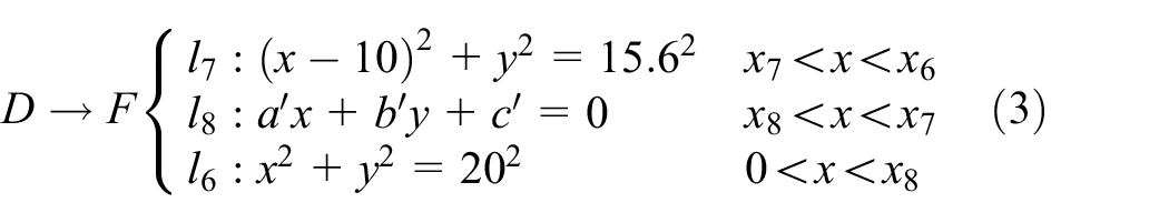
where x3 is the coordinate of left cylinder profile arc l4 and abscissa axis; x4 is the abscissa of point about common tangent l5 and left cylinder profile arc l4; x5 is the abscissa of point about common tangent l5 and upper cylinder profile l3; x6 is the coordinate of right cylinder profile arc l7 and abscissa axis; x7 is the abscissa of point about common tangent l8 and right cylinder profile arc l7; x8 is the abscissa of point about common tangent l8 and upper cylinder profile l6.
The air inlet lies on upper cylinder profile and next to the crossing point of common tangent and upper cylinder profile, ensuring that the air inlet is completely closed by rotor during compression stroke and prevents combustible mixture from going to noncombustible interspace; what is more, the cooperation of rotor and cylinder can avoid gas playing in the cylinder in the same time. Moreover, it is clear that when the designed rotary speed of rotor is below the intrinsic frequency of piston, it does not cause the torsional deflection of piston and has little influence on seal, because the width dimensions of piston is greater than length, and one side of piston is rooted in the groove of rotor and other side in contact with cylinder depends on deformation.
Motion model of rotor–piston assembly
The motion of rotor–piston system can be regarded as the movement of a rotating member which earns four wings that are rooted in the outside of rotor and rotating along with rotor and is regarded as a whole part. This research mainly focuses on the force analysis of flexible piston which is from the acting force of cylinder and rotor, and the movement of piston is analyzed when the rotor is operating under the actuation from the combustion of combustible mixture.
Force analysis of piston
The motion and deformation of the leaf piston can be simplified in Figure 4. The leaf piston is taken as a cantilever, whose one end is rooted in the rotor and the other is in contact with cylinder and moves with rotor. 23 It can be observed clearly that the force P is loaded on the free end and impels transformation so as to simulate the bend of piston. It is clear that the result of integrating about the bending line (A1→B1) is equal to the length of piston (L), so that the forcing situation can be obtained. Thereafter, the precise force P and horizontal displacement (Δ) of free end can be obtained by sufficient trial and error, and the precise deflection of piston can be gained.
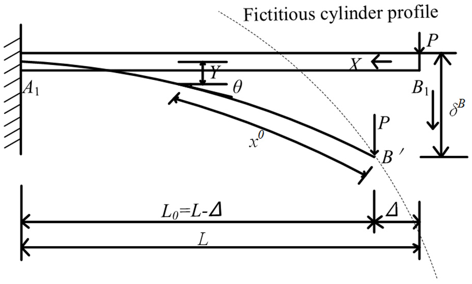
The load of leaf piston.
Motion equation
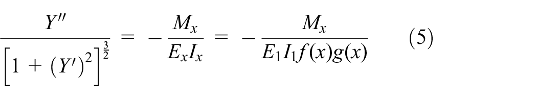
The rotor–piston assembly is regarded as cantilever structure and always keeps complete elasticity. Taking no account of the complicate dynamics trait during the working process, the deforming of the flexible piston is caused by a concentrated load which is imposed on the free end. The geometric nonlinear deforming of the flexible piston can be described by the Euler–Bernoulli equation. It is shown in equation (4)

Equation (4) is a second-order nonlinear differential equation; as the exact solution is extremely difficult to obtain and equation (4) indicates that deflection is not the linear function of bending moment or loading, superposition principle does not fit well. Therefore, it should be solved solely for each case of large deformation and it will become more complicated when the flexural rigidity upon the section is changing. Hence, in order to solve more conveniently, equation (4) can be converted to equation (5)
Making

Namely

It is obtained by integrating equations (6) and (7)


Binding with equations (8) and (9), it is easily determined
Then, the Y can be calculated by integration
Taking Figure 4 as the example to explain the solution of these equations, which took as cantilever that concentrated on the load imposed on the free end.
Supposing

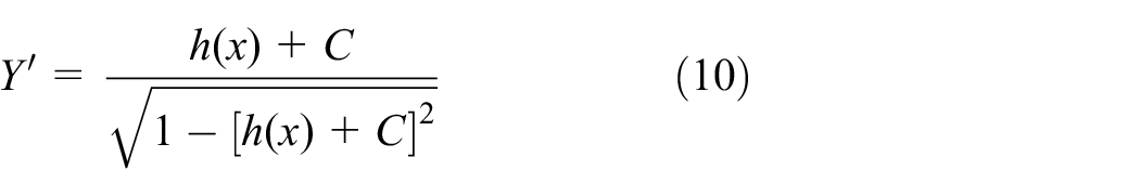
Equations (8), (10), and (11) can be replaced respectively as follows


The uniform cantilever beam of concentrated load on the rod end includes

Then, ensuring the integration constant C through the boundary conditions, when x = L0 = (L – Δ), Y′ = 0, C can be obtained by using equation (13)
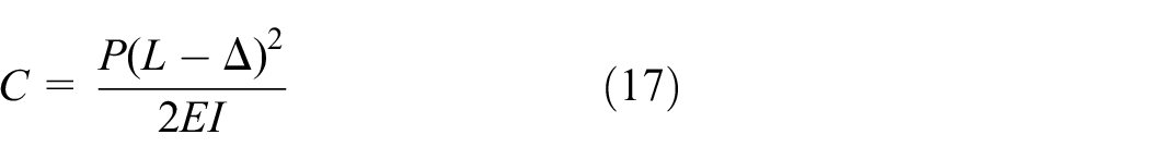
Namely

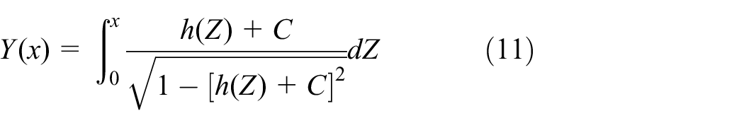
The deflection Y can be obtained from equation (15) when 0 ≤ x ≤ L0, as well as it should meet the boundary conditions that deflection is zero when x = L0, in which the integration constant C can be certain. However, equation (18) is the function of uncharted cantilever’s horizontal displacement of free end Δ, and Δ can be obtained from equation (19)

The eventual results are obtained by trial and error, that is, a constant Δ is substituted into equation (18), equation (18) is substituted into equation (14), equation (14) is substituted into equation (19) to obtain the value of L and it goes on until the calculated value L equals the actual length L of beam, and this illustrates that the constant Δ is the actual horizontal displacement, that is, after Δ is ascertained, the formula of Y′ can be known clearly, and the ultimate deflection y can be obtained from equation (15).
Where M is the bending moment of free end about flexible piston, P is the concentrated load of free end, EI is the bending rigidity of piston, l is the horizontal displacement of free end, L is the length of integral about suspension period of piston, L0 is the actual length of suspension period of piston, Y is the deflection of piston.
Calculation method
It is clear that the motion of piston is nonlinear, and the calculation of the motion of piston needs to be paid great attention on deflection of contact point between piston and cylinder. This segment introduces the scheme to analyze the motion of piston and find the regularities of the motion. The basic method is trial and error,24,25 and a MATLAB program is built to calculate the horizontal displacement l in every load step imposed on the free end. The flowchart of the MATLAB program is shown in Figure 5. The deflection curve of flexible piston was obtained by fitting the leaf piston length, and then defined the volume of combustion chamber by mathematical integration. The first portion illustrates the definition of the parameters in this calculation flowchart and how they would be changed with the cycle; the second portion presents the method with which to obtain the cross point of piston and cylinder; and the last portion indicates the result and conclusion of this flowchart, which is aiming to obtain the motion law of leaf piston.
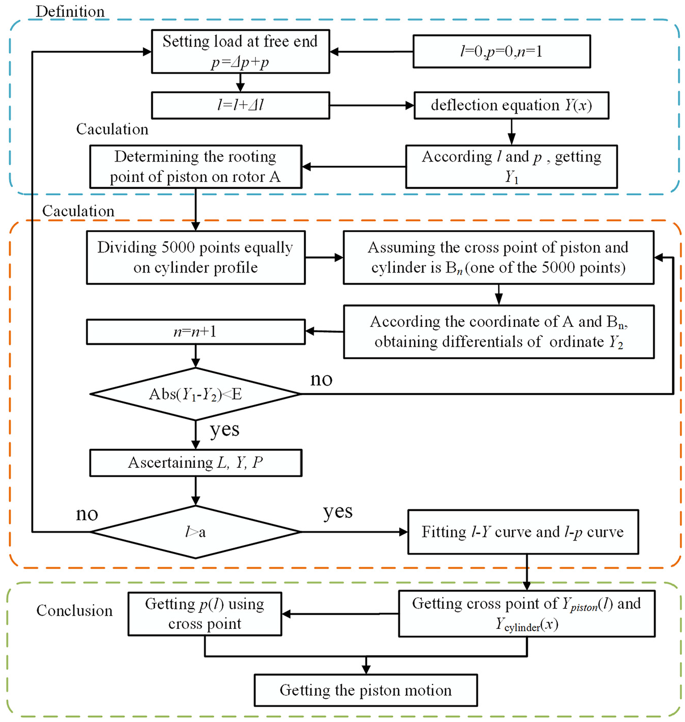
Calculation method of piston motion.
Results and discussion
Motion performance
Using the above-mentioned calculation method, the leaf piston motion of the ER-MEPS was obtained, including the changing of contact point on the leaf piston and cylinder, the horizontal shift of free end on the piston, and the altering of force imposed on the free end on piston. Moreover, the ER-MEPS has two opposite combustors, and each combustors consists of two pistons which are installed in the rotor, so the motion of the former piston differs from the latter piston. Furthermore, the distribution site of the two pistons on the rotor also influences greatly on the piston motion.
The research of the relationship between load and piston change is the premise of motion analysis. Figure 6 shows the deflection and horizontal displacement of free end of piston. It can be observed that the deflection of piston free end shows a linear relationship with the load. The horizontal displacement of piston free end is changing with the increase in load, and the variation trend grows steadily at first and then increases sharply, that is, the engine ignores the effect of horizontal displacement if the load is extraordinarily weeny. Besides, the contact point between piston and cylinder is not necessarily the end point of the leaf piston due to the constraint of the cylinder profile, which varies every moment. The calculation result of deflection and horizontal displacement of piston free end provides a convenient guidance to judge the contact point of piston and cylinder.

Relationship of piston deflection and load.
Figure 7 plots the variation of contact point of pistons and cylinder in a working cycle, in which the ordinate is the distance between free end and fix end (DBFF) and the abscissa is the rotation angle of rotor. Clearly, the former piston and latter piston show different DBFF due to their different installation site. Moreover, the rotor profile and cylinder profile play crucial role in the variation of DBFF, and the tendency of variation is not sharp as the contact point lies in the cylinder profile which is cambered. This demonstrates that the contact point lies in the upper portion of the cylinder profile when the imposed load comes from the inside face of cylinder. However, as known from the design, the cylinder profile consists of different arc trajectories, and the intersection of these arcs corresponds to the inflection of the shown curve in Figure 7.

The distance between free end and fixed end.
It should be noticed that the tagged alphabets correspond one-to-one to Figures 7 and 3 with the rotation of rotor. A→B, the back piston lies in the left-most cylinder profile finally so that the DBFF reaches a peak; B→C, the DBFF continues declining because the cylinder profile is close to the rotor profile until the contact point locates in C which is the crossing point of tangent line and downside arc trajectory in the third quadrant on cylinder profile; C→E, the DBFF is steady as arc l3 is rotating with the origin of coordinates and the rooted point of piston on the rotor profile is also twirling with the origin of coordinates, and the locus of rooted point of piston and arc l3 can be seen as a concentric circles, so that the DBFF stays invariant; E→F, the distance between cylinder and rotor is increasing until F which is the rightmost of cylinder profile, which increases DBFF; F→G, the distance between cylinder and rotor decreases, which shortens DBFF and G is the crossing point of tangent line and upper arc trajectory in the first quadrant on cylinder profile; G→I, just similar to the C→E; I→A, the distance between cylinder and rotor increases when contact point goes through I which is the crossing point of tangent line and upper arc trajectory in the second quadrant on cylinder profile, which leads to the augment of the DBFF. Besides, the motion of back piston is followed by front piston, and the difference is the site of contact point on cylinder profile, as presented in Figure 7. Therefore, it is easy to understand the motion of piston and make certain the variation of pistons, so that the further studying of this power system could be proceeded. In addition, the velocity and accelerated velocity of contact point can be shown in Figure 8. The variation of velocity and acceleration about contact point results from the displacement change. It significantly shows the process of compression and extension on leaf pistons and the velocity and accelerated velocity are not identical in the same angle but contain analogical motion characters.
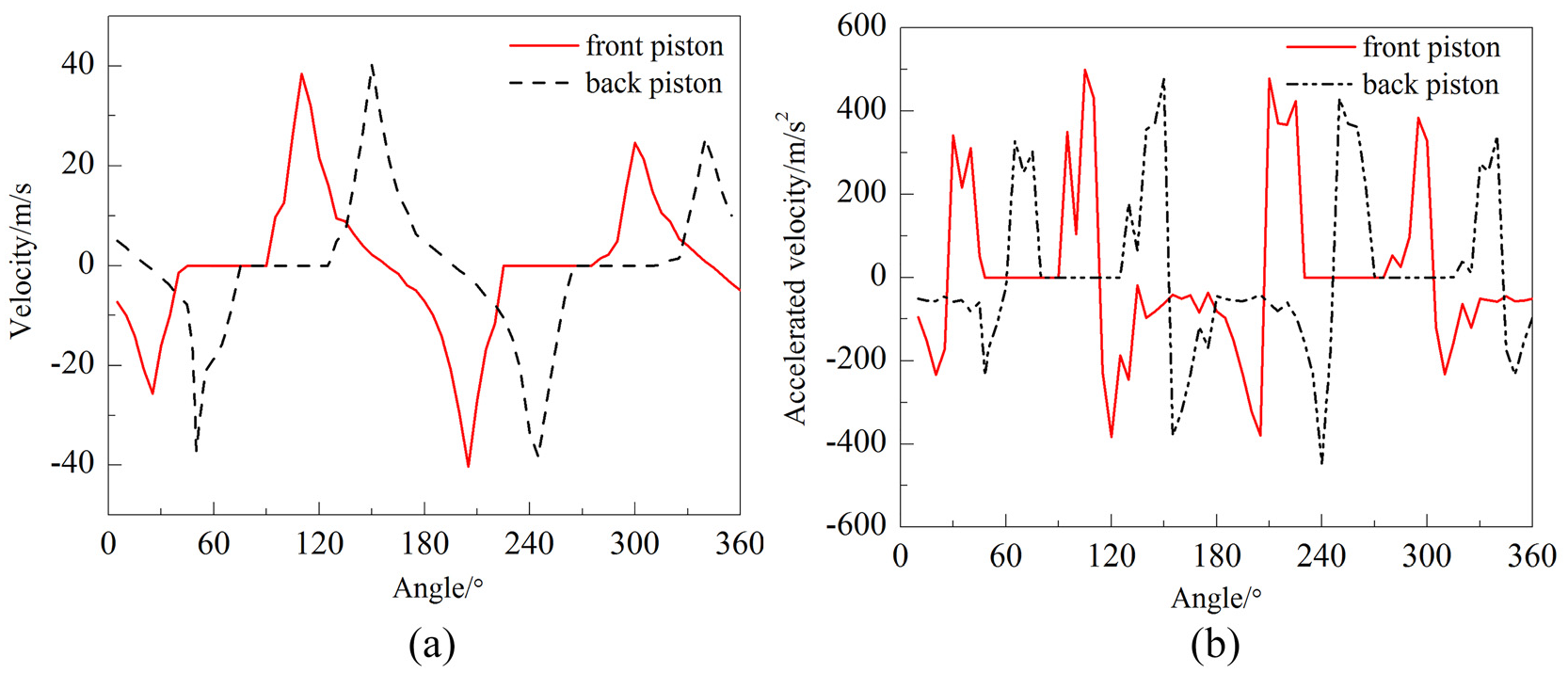
The velocity and acceleration of contact point: (a) velocity and (b) acceleration.
Volume variation of combustor
The combustor is the power source of the ER-MEPS, and its volume change is extremely significant to the work of this power system in terms of dynamics, combustion, and thermodynamics. The simulation result of piston motion can be used to calculate the volume of combustor. The volume variation of one combustion chamber with the rotating of rotor is plotted in Figure 9. Clearly, the combustor volume certainly obeys a definite regularity, which is crucial to further research such as the calculation of combustion. Moreover, the compression, expansion, exhaust, and intake strokes are clearly presented. Besides, the expansion volume is larger than compression volume, which means the expansion ratio is higher than compression ratio for this system. Furthermore, there are two constant-volume durations of the combustor, and one is after compression which implies a possible realization of true isovolumetric heating from combustion, meeting the requirement of Humphrey cycle. On one hand, the ER-MEPS can overcome the unreal constant-volume heating process of Otto cycle in combustion engine, greatly improving the conversion level of fuel chemical energy. On the other hand, the larger expansion ratio of the ER-MEPS makes that the more thermodynamics energy was converted to expansion work.
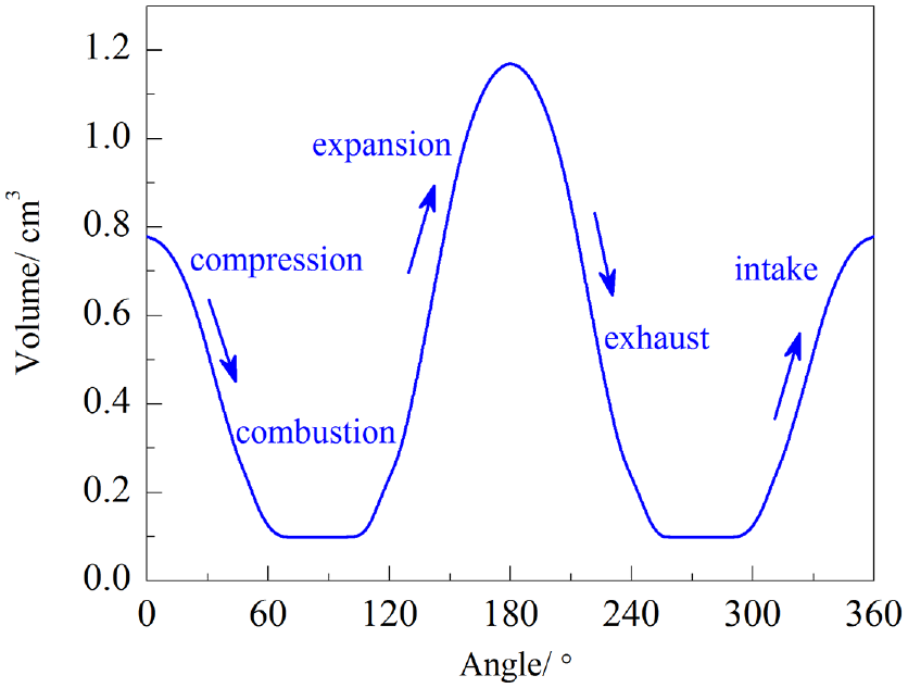
Volume of the combustion chamber.
Effect of piston length
In terms of the above discussion, the piston motion and variation of combustion chamber volume have been presented. However, the piston length and installation site have great influence on them. Figure 10 shows that the variations of deflection and horizontal movement of the free end are due to the different piston length. Observably, the deflection of different piston lengths grows steadily along with the increased load, and the deflection changes more distinctly with the gradual enhancive length of piston, which means the longer piston is more beneficial to find out the regularity of piston motion. Meantime, the horizontal movement of free end on the piston presents similar variation; the difference is that the horizontal movement rises sharply with the augment of load. Therefore, it is simple to investigate the motion of contact point if the variation of deflection and horizontal movement on free end is learned before.
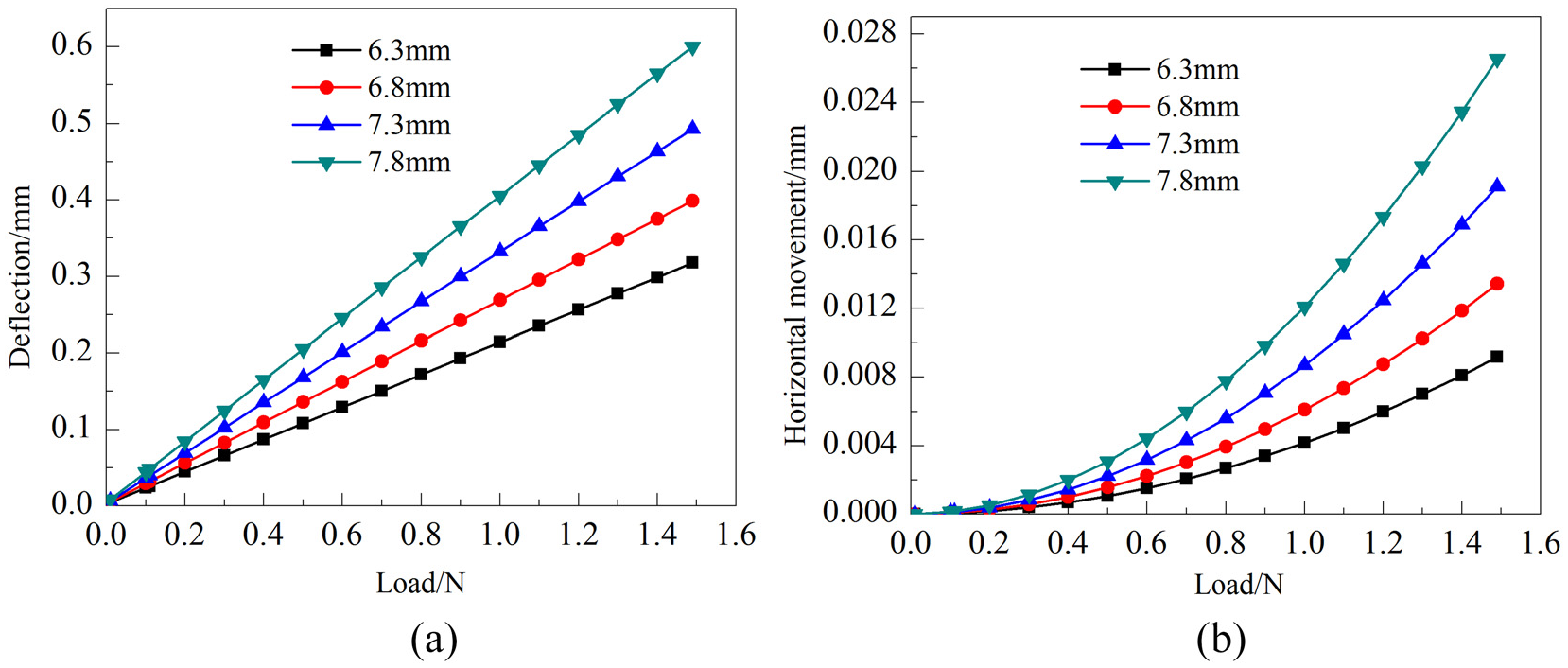
(a) Deflection and (b) horizontal movement.
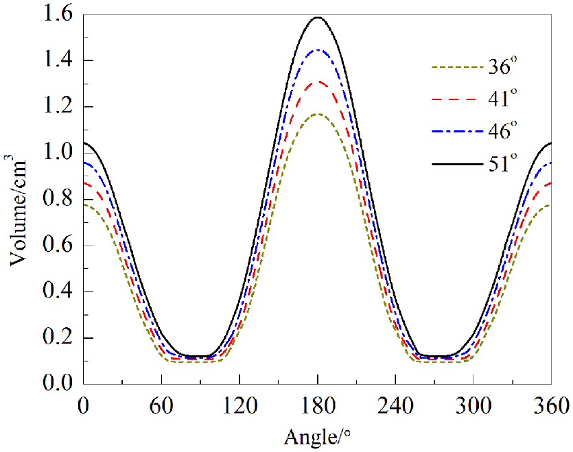
The combustion chamber volume changed with the rotation of rotor can gain easily, and the different length of pistons has influence on the volume, which is presented in Figure 11. The piston lengths are set to 6.3, 6.8, 7.3, and 7.8 mm and installation angle is 46°. However, the volume has not changed acutely, and it demonstrates an almost identical value in these conditions, but the utmost volume presents subtle variation, indicating that the disparate piston lengths have little influence on the volume of combustion chamber. The reason is the utmost distance between free end and fixed end of different pistons does not reach 6 mm, the longer piston length has little effect on the contact point between piston and cylinder profile.

Effect of piston length on combustor volume.
Effect of piston location
The installation site of pistons gives a great influence on combustor volume, although the piston motion is stable. Figure 12 shows the effect of installation phase angle of two pistons on the combustor volume. Observably, the variation tendency of the four volume curves is extremely analogical. However, the maximum and minimum volumes are affected by the piston location, which vary in positive correlation with the installation phase angle, that is, the larger installation phase angle leads to larger combustor volume. As a result, in order to gain the greater power and to keep engine work more smoothly, the installation angle of leaf pistons should be properly large for this new system.
The effect of pistons location on combustor volume.
In addition, the compression ratio and expansion ratio are also changed by the installation phase of pistons. Figure 13 makes clear that the compression ratio has a maximum value over the whole range of installation phase angle, suggesting that more high energy efficiency is expected by either shortening or enlarging from the certain installation phase angle of 50°. Meanwhile, the variation of expansion ratio shows similar tendency. The disparity of the expansion–compression ratio is not extremely distinct along with the augment of installation angle, which illustrates the compression ratio and expansion ratio have certain relation in various installation angles.

Variation of expansion–compression ratio.
Figure 14 shows the effect of piston installation site on the minimum volume duration, compression duration, and expansion duration. It is easily found that the compression and expansion last longer when the installation phase angle is larger and the constant-volume duration is shorter. Too short constant-volume period generally reduces the level of isovolumetric combustion, and too long period may lead to high heat loss transferred from the high temperature gas to cylinder wall. Therefore, the appropriate installation angle is extremely important to the operation of this novel ER-MEPS.

Effect of piston location on strokes.
Conclusion
This study presented a new MEPS and performed a research to analyze its motion characteristics. The effect of piston installation site and piston length on the combustor volume was also revealed. The main conclusion can be summarized as follows:
The ER-MEPS is featured potentially with balance operation, direct energy conversion, flexible combustion, new thermodynamic cycle, and true isovolumetric combustion heating.
The leaf piston motion of the ER-MEPS is decided by the cylinder profile rather than by some mechanisms like the crank-slider in convention crankshaft engine, and the contact point of piston and cylinder profile is not the piston end and it keeps moving with the rotation of rotor.
The combustor of the ER-MEPS is periodically compressed and expanded by following the rotor and piston motion, and its volume variation can be used to perform the intake, compression, expansion, and exhaust of a novel Humphrey thermodynamic cycle. Besides, the minimum combustor volume lasts an amount of time.
The length of leaf piston has little effect on the combustor volume and the contact point of piston and cylinder. However, the work volume of combustor varies in positive correlation with the installation phase angle of pistons.
The maximum compression ratio is achieved in an optimism installation phase angle. Moreover, a larger installation phase angle of pistons means a longer compression and expansion process, while the constant-volume duration is shorter for combustion process.
Footnotes
Handling Editor: Andreas Rosenkranz
Declaration of conflicting interests
The author(s) declared no potential conflicts of interest with respect to the research, authorship, and/or publication of this article.
Funding
The author(s) disclosed receipt of the following financial support for the research, authorship, and/or publication of this article: This work was sponsored by the National Natural Science Foundation of China (Grant No. 51805056), Natural Science Foundation of Chongqing, China (Grant No. cstc2019jcyj-msxmX0407), and the Open Fund of Chongqing Key Laboratory of “Human-Vehicle-Road” Cooperation & Safety for Mountain Complex Environment (Grant No. 2018HVRC03). The authors express their sincere gratitude to the sponsors.