
Abstract
Thermal energy storage has been considered as an important solution to extend the operation of a concentrated solar power plant by meeting the peak demand of power in the time period from sunset to night, or providing power during cloudy days. Discussed in this work is a thermocline thermal energy storage system with a solid filler material. For this reason, a one-dimensional single-phase model is developed and validated with experimental data to investigate the thermal behavior of such thermal energy storage. The described model is further applied to design a 100-kWhth thermocline thermal energy storage system with a packed bed of quartzite rocks and oil as the heat transfer fluid. A synthetic oil (Therminol VP-1) and a vegetable oil (rapeseed oil) are the two candidates to be used as the heat transfer fluid. Their thermal and economic performances are calculated and compared. The results show that rapeseed oil is more cost-effective than Therminol VP-1 offering a lower energy cost (€18.3/kWhth vs €92.925/kWhth for Therminol VP-1).
Keywords
Introduction
The increasing contribution of renewable energy sources like solar energy in power cycles mandates the use of thermal energy storage (TES) systems to solve the problem of the intermittent character of solar energy. By storing excessive unused energy and supplying it back when required, TES technologies help in balancing the energy generation and demand. Using an appropriate TES system can enhance the power plant profitability and reliability.
From all renewable technologies, concentrating solar power (CSP) is the only technology that can integrate a cost-effective TES. 1 TES systems are of three types: latent heat storage (LHS), sensible heat storage (SHS), and thermo-chemical heat storage (TCHS) systems. The SHS system has the advantages of low-cost storage material, ease of maintenance, and low degradation of heat transfer between the solid material and the heat transfer fluid (HTF). On the other side, the principal disadvantages of the SHS techniques are the large storage volume required and the temperature degradation due to the energy addition and extraction. 2 In fact, TES systems must meet several requirements in order to achieve high efficiency and storage capacity: good heat transfer between solid media and the HTF, high stability of the HTF and the solid media under high temperature (chemical and mechanical), high energy density, and low cost. 3
Single-tank TES using a packed bed of porous materials and HTF has received great attention by researchers in recent years. In fact, much research has been conducted dealing with different characteristics of sensible storage systems. Researchers investigated many filled materials (gravel, sand, concrete) and different HTFs (water, synthetic oil, gases, compressed air, and vegetable oils). They found that alumina, graphite, rocks, and high-temperature concrete are the most suitable filler materials for SHS systems.4,5 Iniesta et al. 6 and Diago et al. 7 proved experimentally that natural desert sand is a good material to store sensible heat up to 800°C.
Numerical modeling is used to better understand the thermal behavior of the storage tank and gives possible solutions to optimize thermal performances of the system. Different numerical models have been developed for this purpose. Some researchers consider the solid and fluid temperatures to be equal using a single-phase model. Others adapted the Schumann 8 model considering two different temperatures for solid and fluid. In this context, Beasley and Clark 9 reviewed all the two-phase models and the single-phase ones. Singh et al. 10 published a large list of research dealing with packed beds. Since then, one-dimensional models have been developed and then expanded to two-dimensional models11,12 and even three-dimensional ones 13 have been established. Non-homogeneous models have been then developed in order to examine the influence of particle shape and size on the thermal performances of packed beds. 14 Van Lew et al. 15 and Li et al. 16 developed a 1D two-phase model with constant solid and fluid properties and without taking into account heat losses and investigated the effect of different parameters on the TES performances and proposed charts storage system design. Wu et al. 13 studied storage systems with different concrete structures as the filler material and with various HTF velocities (thermal oil).
The HTF has a great influence on the thermal efficiency of the storage tank. In fact, various fluids have been used in packed bed storage tanks. Zanganeh et al. 17 designed a 7.2-GWhth TES system based on a packed bed of rock using compressed air as the HTF. It was found that initial charging of the storage system improves significantly its thermal performances. Bruch et al. 18 conducted experimental and numerical investigations of a pilot-scale packed bed using thermal oil for a CSP power plant. In this study, it was proved that the rock bed and the HTF have the same temperature and that the heat transfer is a 1D process. El Alami et al. 19 conducted a numerical study of a packed bed TES system using Moroccan rocks as the filler material and Therminol VP-1 as the HTF. They concluded that high HTF mass flow rate and high values of aspect ratio lead to greater thermal performances. Erregueragui et al. 20 proposed an eco-friendly storage system using quartzite as the filler material and palm oil as the HTF and found that palm oil could be used efficiently as the HTF for a packed bed storage system having a working temperature under 300°C. Hoffmann et al. 21 investigated the possible use of vegetable oil as the HTF in both solar field and TES systems. They found that it can be a good alternative to conventional oils with good thermal and economic performances.
In addition to the thermal performance requirements, a TES system should have a low capital cost. This cost depends on the HTF and solid cost and from other cost and performances factors. A TES system is considered cost-effective only when it reduces the cost of the energy. 22 Thus, a dedicated numerical model, validated with experimental data, is used to design a 100-kWhth storage tank. Synthetic and vegetable oils are used in this simulation and their thermal and economic performances are compared.
Model description
A 1D single-phase numerical (1D-1P) model was developed and computed with FORTRAN in order to investigate an SHS system. The considered system is a vertical cylindrical tank filled with porous solid material in which a HTF flows through its void fraction. During the charging phase, the hot HTF enters the tank from the top and leaves from the bottom. During the discharging phase, the cold HTF penetrates from the bottom and leaves from the top after being heated. Figure 1 presents the considered storage system.
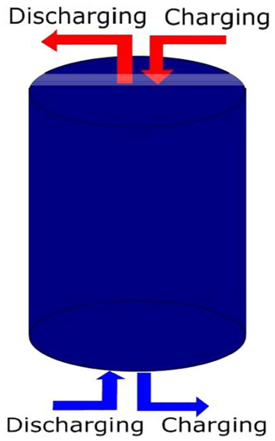
Schematic of the thermocline thermal energy storage system.
The fluid flow is considered 1D and uniform inside the tank. The proposed model focuses only on the thermal behavior of the tank, so that the fluid flow equations are not considered. The heat transfer conduction inside the solid particles is considered negligible because of a small Biot number (Bi < 0.1). The porous medium is a homogeneous, continuous, and isotropic solid. The numerical model takes into account the heat losses through the tank wall by the use of effective parameters. In order to be more accurate, only the variation of thermo-physical properties of the HTF with temperature is taken into account.
Development of a 1D-1P model
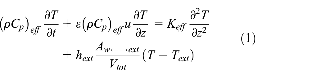
The developed model focuses on the thermal balance equation. The temperature of the HTF and the porous material is considered equivalent in all points inside the tank and during all the charge and discharge periods. In addition to the temperature distribution and evolution within the tank and over time, the model leads to the prediction of the thermal performances of the storage tank. The governing equation is expressed as follows
The HTF mass flow rate is calculated using equation (2)

The velocity of the HTF through the granular medium is deducted from the mass flow rate

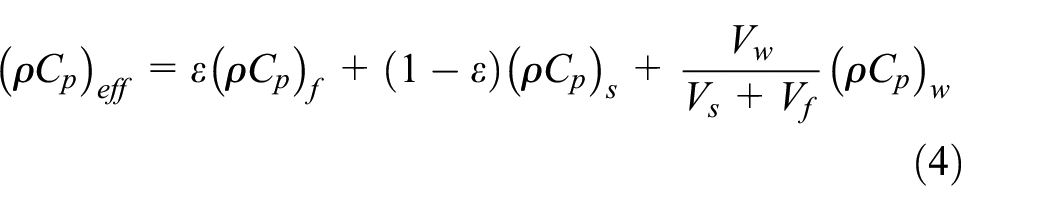
Equations (4) and (5) detail, respectively, the mathematical expression of the effective volumetric heat capacity (ρCp) eff and the effective conductivity keff

The heat loss coefficient hext is deduced from the expression of the thermal resistance

where hair is the convection coefficient for laminar incompressible flow over a flat surface and is determined using the following equation 23

Initial and boundary conditions
The determination of the initial and boundary conditions is an essential step to solve the thermal balance equation.
The initial condition for the discharge phase is

For the discharge phase, there are two boundary conditions: one in the top of the tank and one in the bottom. In fact, the cold HTF penetrates the reservoir from the bottom (z = 0)

and after being heated it leaves from the top (z = H)

Numerical method
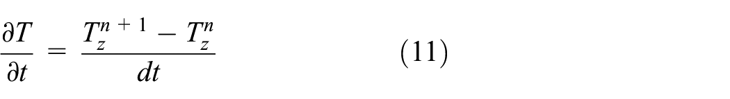
The thermal balance equation described above is solved using finite difference methods. The convective term is discretized using a first-order forward scheme (implicit scheme for time discretization). It is described as follows
The first-order spatial derivative term is solved using a backward differencing scheme

and the second-order central differencing scheme is used for the second-order spatial derivative

In order to check the stability of the discretization, we integrate the Courant–Friedrichs–Lewy coefficient. This coefficient is used to judge the divergence of the numerical results in any problem of displacement of fluid. In the case of convergence, its value must be less than 1. It is expressed as follows
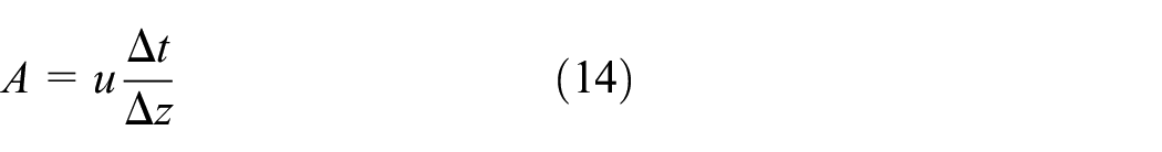
This coefficient compares the distance between two nodes and that traveled by the fluid during a fixed time step Δt.
Mesh sensitivity
Spatial mesh
The numerical results obtained are sensitive to the type of mesh and the number of nodes used in the field to be studied. For this reason, a precise study of the mesh must be elaborated. On the other hand, it is necessary in the simulation work to minimize the computational time. Hence, in order to make a compromise between a precise result and an optimized computational time, we studied the variation of the temperature profile at the end of the charge phase as a function of the number of nodes. The results are shown in Figure 2.
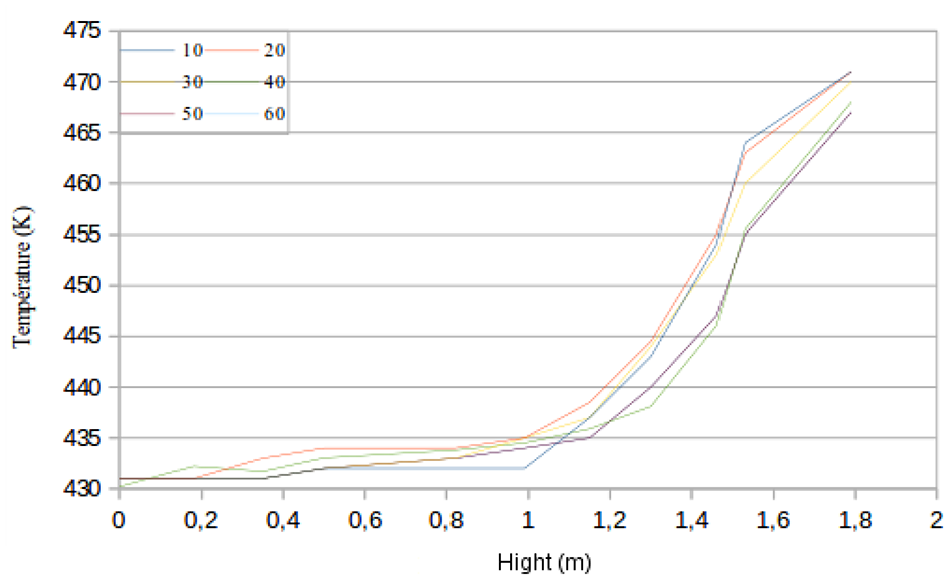
Temperature profile for a charge phase with different values of spatial nodes.
When comparing the results obtained, we notice a significant temperature difference between the results for low numbers of nodes (between 20 and 30 nodes). We find that, beyond a node number equal to 50, the results are identical and no differences are perceptible. So, for the rest of this work, and for a minimal calculation time and a good precision, a mesh of 50 nodes will be considered.
Temporal mesh
Once the spatial step is fixed, it is necessary to choose the time step for the simulation. Indeed, just like the spatial mesh, the choice of the fineness of the temporal mesh is a primordial question in numerical simulations: the more small the time step is, the less the differences between the simulation and the reality are, but the higher the cost of the calculation is. So, to make a suitable choice, it is necessary to respect the two constraints of time and precision. In addition, it is necessary to validate the conditions of convergence of the methods of discretization mentioned already.
Figure 3 shows the variation of the temperature profile at the end of the charge phase for different time steps. It is clear that below a time step value of 10–3 s no differences are noticeable in the results. So, for the rest of our work, a time step of 1 ms is chosen.

Temperature profile for a charge phase with different time steps.
Validation of the numerical model
In order to verify the accuracy of the simulation methods used by our computational code, the simulation results were compared with the experimental data provided by Hoffmann et al. 24
In the experimental work, the tank is made of steel. Its storage capacity is about 8.3 kWhth. Rapeseed oil is used as the HTF and quartzite as the filler material. The mass flow rate of the HTF was maintained at 0.29 kg/s in charge and 0.19 kg/s in discharge. Initially, the tank is almost completely heated to the high temperature of 483 K. The discharge phase started when the tank was almost entirely at 483 K, by sending oil at 433 K from the bottom of the tank.
The tank is a black steel tube of 400 mm inner diameter. Black or raw steel is preferred over stainless steel because it is less expensive and easier to manipulate. To minimize thermal losses of the tank, it was insulated with 20 cm of rock wool covered with aluminum foil. The tank contained two buffer sections to homogenize the downward or upward fluid flow. Table 1 summarizes the most important parameters of the reference tank.
Main characteristics for the reference tank.

HTF: heat transfer fluid; TES: thermal energy storage.
A 1D simulation of this tank was carried out in order to compare the experimental results to those obtained by the numerical code. Only the previously mentioned data are used as input parameters to the model (Table 1). No adjustment parameters were added. Thermal and thermo-physical properties of the different materials used in this work are summarized in Table 2.
Thermal and thermo-physical properties of the different materials.

The model validation is done by comparing the temperature distribution inside the tank for different heights and in various charge and discharge times as illustrated in Figure 4(a) and (b).
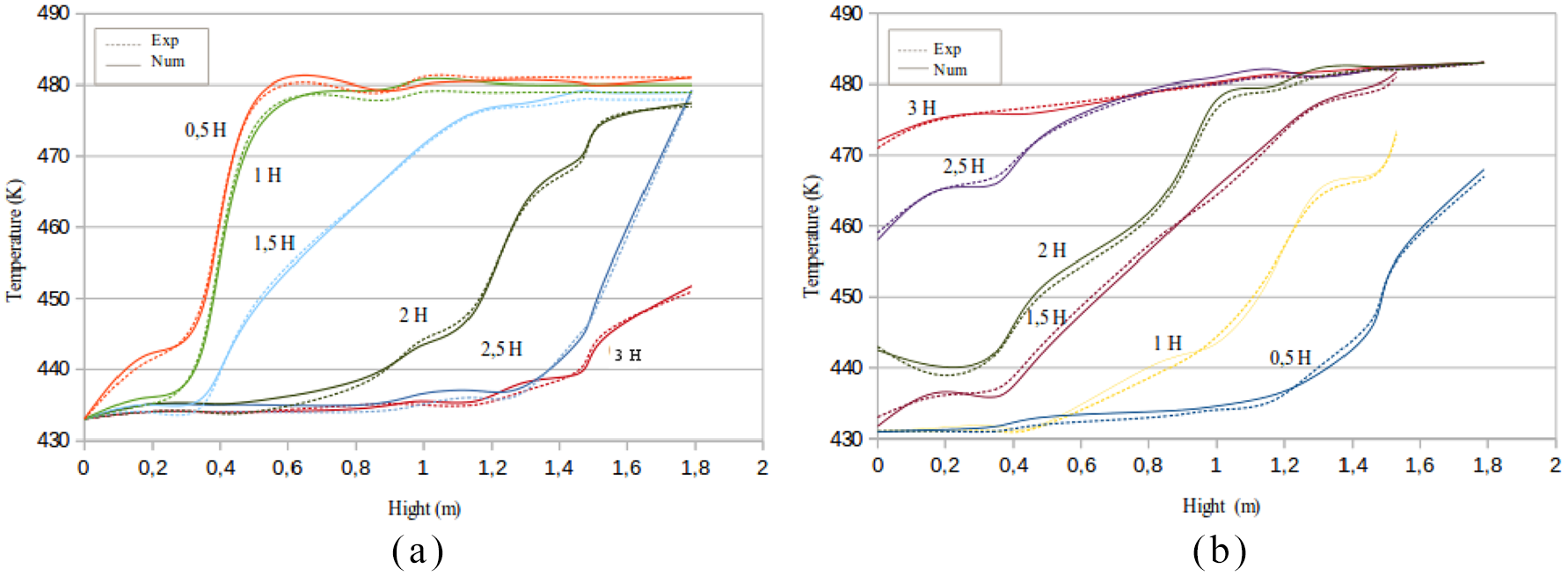
Comparison of the experimental and numerical results during (a) the charge process and (b) the discharge process.
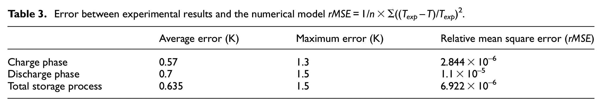
Different errors are summarized in Table 3. They have been calculated from the collected data of 12 experimental temperature profiles and the corresponding simulated results (six temperature profiles during the charging phase and six others during the discharging phase). The average error between the experimental data and our numerical model is about 0.57 K for the charging process with a maximum error of 1.3 K and the value is 0.7 K during discharge with a maximum error of 1.5 K. The numerical results provided by the code and the experimental results are in satisfactory agreement, which validates the accuracy of the simulation and the numerical code. The limit of accuracy of the model may be due to its inherent assumptions. In fact, the model assumes an identical temperature for both fluid and solid in any time and point of the tank. But this assumption can give inaccurate results, especially at the beginning of the discharge phase in the bottom of the tank where the cold fluid is in contact with the hot filled material. As a result, the predicted temperatures are higher than the experimental ones.
Error between experimental results and the numerical model rMSE = 1/n × Σ((Texp – T)/Texp) 2 .
Results and discussion
The objective of this article is to develop a numerical model apt to describe the thermal behavior of any storage tank filled with porous material. The developed model is used then to help in sizing and optimizing storage tanks according to a set of load specifications.
Procedures of sizing of thermal storage tanks
The design of a porous storage tank consists in defining a certain number of parameters that depends on a set of operational constraints. These parameters need to be chosen carefully to ensure an optimal operation and to satisfy the required energy.
The first step consists of the calculation of the tank size. In fact, the determination of the tank size (diameter and height for a cylindrical tank) is dictated by several operational constraints which are the total energy required, the period of the discharge process, the high and low temperatures of the HTF, the porosity of the storage tank, and the thermo-physical properties of the filler material and the HTF.
The ideal volume of the tank (the tank is considered as ideal tank) is calculated using equation (15)

In fact, to meet the requirement of minimizing the temperature degradation, a real volume taking into account the solid filler material should be calculated
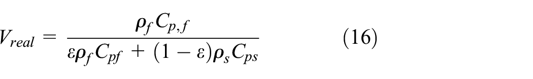
The next step consists in choosing the tank diameter and height that provide the optimal performance of the storage tank for the calculated volume.
After that, the required HTF and filler material masses are calculated using equations (17) and (18)


The thermal performances of the storage tank are calculated using equations (19)–(24)
Emax is the maximum energy that the tank can store

The stored energy is expressed as follows

where Sbed is the surface of the porous bed and Sw is the surface of the wall.
Equation (21) expresses the discharged energy

The thermal energy efficiency of the charge is

The thermal energy efficiency of the discharge is

The global thermal efficiency is

Technical sizing of the 100-kWhth storage tank
In this section, a 100-kWhth storage tank is designed according to a set of specifications. The storage tank is designed for a discharge period of 4 h and an operating temperature between 423 and 473 K. A packed bed of quartzite rocks is used to store the required energy. Two different configurations are proposed using two different HTFs. Table 4 summarizes the required features of the storage tank.
Required features of the storage tank.

HTF: heat transfer fluid; TES: thermal energy storage.
The technical sizing of the storage tank will be proceeded for two different HTFs: rapeseed oil and Therminol VP-1. Thermal performances of the two configurations will be presented and an economic approach will be realized in order to choose the most suitable fluid. The calculation of the real volume leads to Vreal = 3.54 m3 with rapeseed oil and Vreal = 4.06 m3 for Therminol VP-1.
Once the real volume is calculated, the couple H and D must be selected. In order to explore the effect of the geometry on the thermal performances of the storage process, we simulate the model with different H/D ratios for the same storage volume for both cases. Different H/D ratios are tested from 1 to 4 as illustrated in Table 5a and Table 5b.
Effect of the H/D ratio on the thermal performances of the storage tank (in the case of rapeseed oil).

Effect of the H/D ratio on the thermal performances of the storage tank (case of Therminol VP-1).

Figure 5(a) and (b) shows that the discharge efficiency and the discharged energy increase for the two configurations with higher values of H/D. These observations mean that, with a larger height and for the same tank volume, the temperature degradation is reduced and the efficiency is improved. The H/D ratio retained for both cases is equal to 2.5. This intermediate ratio is preferred to a higher ratio as it implies an outward exchange surface less important and then less expensive tank foundations. Then it can be seen from the same figure that variations of the discharged energy and the discharge efficiency for both cases (rapeseed oil and Therminol VP-1) become less pronounced from an H/D ratio equal to 2.5.
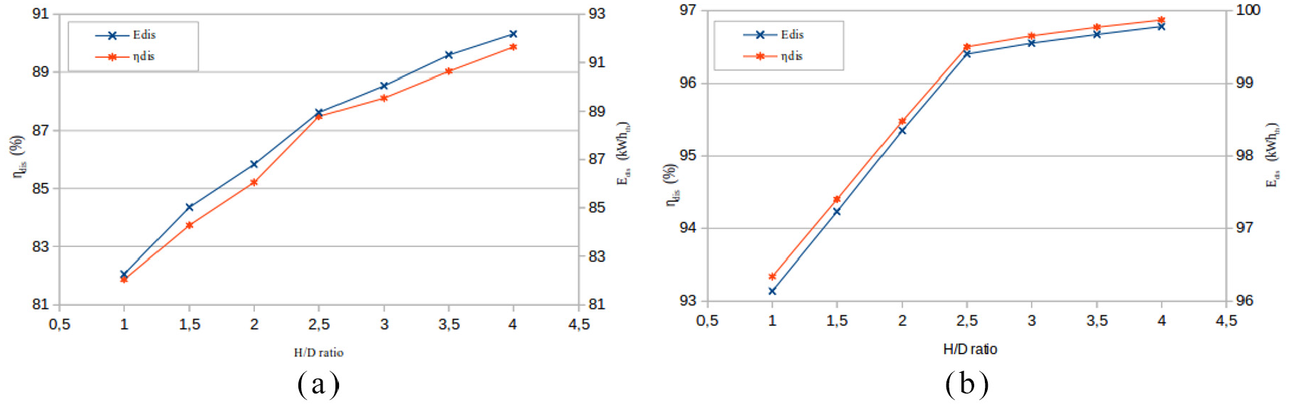
Variation of the discharged energy and the discharge efficiency versus the H/D ratio for the case of (a) rapeseed oil and (b) Therminol VP-1.
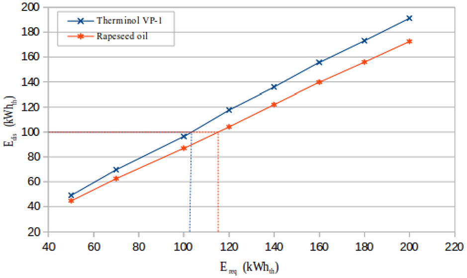
Variation of the discharged energy versus the required energy.
It is clear from Table 5 that the two initial selected configurations do not afford the required storage capacity fixed in advance, that is why initial stored capacity should be oversized in a way to give back the desired energy. At the first attempt, when trying to improve the design, we should always pay attention not to deteriorate the thermal efficiency of the system. Figure 6 presents the variation of the discharged energy versus the required energy. Linear interpolations give the following results: in the case of rapeseed oil, the storage system should be designed for a storage capacity of 115 kWhth, whereas Therminol VP-1 needs a lower capacity of 102 kWhth to give back the same energy (100 kWhth).
Table 6 provides the design parameters of the final configurations for both cases. We see that after oversizing the two systems we obtained the required energy while improving the thermal performances of the first two configurations. It is clear that the thermal performance of the storage system with Therminol VP-1 is higher than that of rapeseed oil (ηg = 94.77% using Therminol VP-1 and ηg = 83.409% with rapeseed oil).
Design parameters for the two configurations.

HTF: heat transfer fluid; TESM: thermal energy storage system.
Economic analysis
The numerical model allows us to evaluate and compare the thermal performances of the two proposed configurations. But the choice of the appropriate one should be supported also with an economic approach. For this reason, a financial analysis is realized comparing the cost of the two configurations. In order to estimate the general costs, the unit prices shown in Table 7 are adopted.25–29
Unit prices of different used materials.

The comparison of the two general costs shows a great difference between the two configurations. In fact, a reasonable economic approach should be based on the kWhth cost. As shown in Table 8, in the first configuration, the kWhth costs about €18.3. The second configuration is more expensive, that is, €92.925/kWhth. On the other hand, it can be seen that the fluid cost represents the greatest part of the total charges. Therminol VP-1 represents 92% of the general costs, while rapeseed oil represents only 56% of the total charges. Thus, using rapeseed oil seems to be much more economically profitable despite its lower thermal efficiency. Then, rapeseed oil is more eco-friendly than synthetic oils. In fact, Therminol VP-1 emits a larger amount of greenhouse gases (GHG; 3 kg CO2 eq/kg vs less than 2 kg CO2 eq/kg for rapeseed oil) 30 and rapeseed oil is highly available.
Economic analysis results.

Conclusion
Thermal performances of an SHS system with quartzite rocks as the filler material and oil as the HTF were analyzed using a 1D-1P model. The parametric study was elaborated in order to optimize the design of a 100-kWhth storage system. A detailed study of the thermal behavior of the tank was conducted by studying the effect of the H/D ratio on the thermal performance of the system. Two optimal configurations using two different HTFs (Therminol VP-1 and rapeseed oil) were presented. Finally, rapeseed oil was found to be more cost-effective than Therminol VP-1.
It was found that the themal performance (discharge efficiency and discharged energy) of the storage tank increases with a higher H/D ratio.
An intermediate H/D ratio of 2.5 is chosen for both configurations.
Therminol VP-1 gives better thermal performance with a global thermal efficiency of ηg = 94.77% versus ηg = 83.409% for rapeseed oil.
Footnotes
Appendix 1
Acknowledgements
The authors are particularly grateful for the valuable and supportive views of Mr. Mahmoud Hammadich.
Handling Editor: James Baldwin
Declaration of conflicting interests
The author(s) declared no potential conflicts of interest with respect to the research, authorship, and/or publication of this article.
Funding
The author(s) received no financial support for the research, authorship, and/or publication of this article.