
Abstract
Heat exchangers capable of withstanding high temperature and pressure are required to achieve increased thermal efficiency and compactness. A welded plate and shell heat exchanger, developed for applications involving pressures up to 150 bar and temperatures up to 600 °C, has exhibited advantages that allow a more wide use of heat exchangers. However, few studies have tested the structural integrity of the plate pack of this design. In this paper, the structural integrity of the heat transfer pack was tested using finite element analysis. Elastic and elastic-plastic models were applied for one set of heat transfer plates, while layers of two and four plates were used to verify the effect of the boundary conditions. The plate results were evaluated according to the ASME Boiler and Pressure Vessel Code, Section VIII Division 2. Finally, the function of the end plate in the plate packs was numerically studied.
Keywords
Introduction
Plate heat exchangers are commonly used in a wide range of industrial applications including chemical processes, energy, refrigeration, and cryogenic fields. 1 Gasketed plate heat exchangers with operating temperatures ranging from −50 to 350 °C and pressures ranging from full vacuum to 40 bar have been developed for high thermal efficiency and compactness. 2 However, these heat exchangers are subject to many temperature and pressure constraints. Welded plate heat exchangers, however, have a wider range of use compared with gasketed plate heat exchangers.
Blomgren et al. 3 described the structure of a welded plate heat exchanger, where the edge portion of each heat transfer plate is welded to that of a first adjacent heat transferring plate along an outer line, and to the edge portion of a second adjacent heat transfer plate along an inner line.
The plate and shell heat exchanger (PSHE) shown Fig. 1 was first commercially produced by Vahterus. 4 The PSHE, which is a welded heat exchanger, was developed for applications at pressures up to 150 bar and temperatures up to 600 °C. 5 Owing to these advantages, it is being used in more fields. However, few studies have tested the structural integrity of the plate pack of the PSHE.

Configuration of PSHE. (a) Assembly and flow direction. (b) Exploded view.
In this paper, the structural integrity of the heat transfer pack of the PSHE is tested through finite element (FE) analysis. Elastic and elastic-plastic models are applied for a set of heat transfer plates. Analysis results are evaluated according to the ASME Boiler and Pressure Vessel Code, Section VIII Division 2. 6
Finite Element Modeling
Material properties
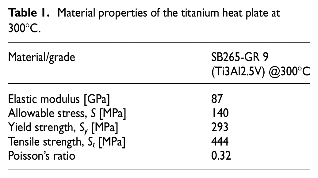
The working fluid in a PSHE is pressurized water, and the design temperature is 300°C. The material properties of the titanium heat plate at 300°C were obtained from ASME Section II, Part D 7 and are given in Table 1. Fig. 2 shows the stress–strain curve used in the elastic-plastic analysis.
Material properties of the titanium heat plate at 300°C.
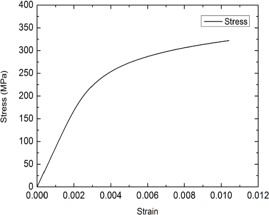
Stress–strain curve used in the elastic-plastic analysis.
Design criteria
The allowable stresses for the elastic and elastic-plastic design are provided in Part 5 of the ASME 2017 Boiler and Pressure Vessel Code. 6 In the elastic design, the primary von Mises limits are as follows:


where S is the allowable stress; Pm is the general membrane stress; PL is the local membrane stress; Pb is the bending stress; and σ1,σ2, σ3 are the principal stresses. Eq. (1) is the criteria to evaluate the protection against plastic collapse, and Eq. (2) is the criteria to provide an approximation of the protection against local failure based on elastic analysis.
In the elastic-plastic design, the local failure is evaluated based on the triaxial strain. The limiting triaxial strain εL is determined using

for an acceptable strain of

where
According to Table 5.7 of Ref. [6],

for titanium, where Sy and St are the yield and tensile strengths of the material, respectively.
Finite Element Modeling and Analysis
To reduce computation time, one quarter of a heat transfer plate was modeled, as shown in Fig. 3. To evaluate the effect of boundary conditions, a stack of two and four adjacent plates were chosen as the analysis regions as shown in Fig. 4. The plates were modeled as both a solid and a shell in FE analysis because the plate thickness is significant compared with groove radius, as shown in Fig. 5.

Quarter-plate model and analysis region.

FE modeling schemes for a (a) two-layer solid, (b) two-layer shell, and (c) four-layer shell.

Shape of the corrugated grooves on the plate.
The nodes on the symmetrical section were fixed in a direction normal to the section surface. Contact between the two- or four-layer plates placed back-to-back was considered as a separation (i.e., two independent pieces touching each other). Because the plate pack is confined longitudinally at both ends, it was assumed herein that the apex of the outer plate in the analysis region was not deformed in the vertical direction of the plate (Fig. 6 and Fig. 7). A pressure of 11.8 MPa was applied in the high-pressure area, as shown in Fig. 7(b). Figure 8 shows the configuration of the shell element with an element size of approximately 0.5 mm.

Displacement boundary condition in two-layer solid considering (a) vertical constraint, and (b) symmetry.

(a) Boundary condition and (b) applied pressure in a four-layer shell.

Shell element configuration.
Results and Discussion
Herein, six cases were considered to obtain the stress and strain on the heat transfer plate under the high pressure of 11.8 MPa, tabulated as CASES 1–6 in Table 2. The number of elements in the solid model (CASE 1) was much larger than that of the shell model (CASE 2 and 3).
Descriptions of analysis cases.

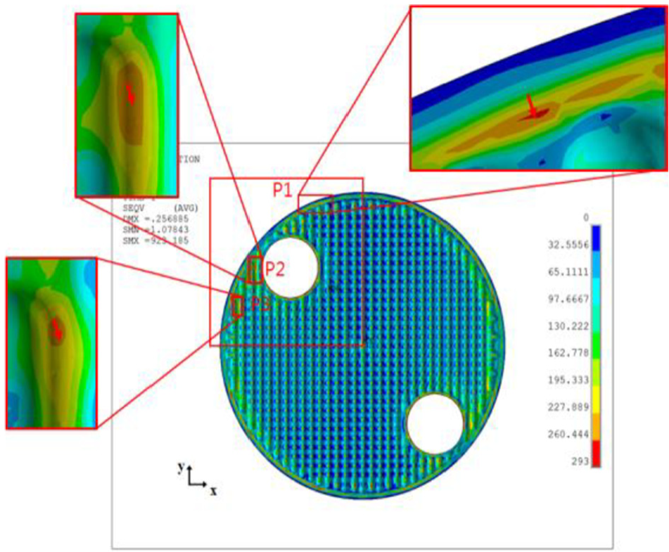
Figure 9 shows the von Mises stress distribution of CASES 1–4, where the stress distributions and magnitudes are similar for all cases excepting the peak stress in the elastic analysis. Points P1 and P2 in Fig. 9(a) represent the weld region at the outer boundary of the plate and porthole, respectively; while Point P3 represents the back-to-back contact region of the plate groove apexes. The stresses present are the local membrane stress (PL), and the local membrane stress plus bending stress (PL+Pb), and both stress types are within allowable stress limits. 6 Figure 10 shows the von Mises stress distribution in the whole-plate four-layer shell model to allow comparison to that in the quarter-plate four-layer shell model (Fig. 9).

Comparison of von Mises stress distribution for CASE 1, CASE 2, CASE 3, and CASE 4.
von Mises stress distribution in the whole-plate four-layer shell model of CASE 6.
In the results shown in Table 3, the stresses of the two-layer solid (CASE 1) and two-layer shell (CASE 2) models are relatively lower than those of the four-layer model (CASES 4–6) owing to the boundary restraint. Also, the validity of the quarter-shell four-layer model was confirmed when comparing the quarter models (CASES 4 and 5) and the whole model (CASE 6) of the plate.
Stress values at locations P1 and P2 (Fig. 9) and the allowable limits.

PL: local membrane stress; Pb: bending stress.
The equivalent stress in the elastic solid analysis at P3 given in Table 4 is unrealistically high because P3 is the restrained contact point. In the elastic-plastic model, the calculated equivalent plastic strain of 0.407% in CASE 5 is much smaller than the strain limit of 7.86%.
Analysis results at location P3 of Fig. 9.

The porthole weld region (red circle) in Fig. 11 shows the plastic deformation for which the von Mises stress exceeds the yield strength of 293 MPa. From Tables 3 and 4, it is seen that the stress distribution in the case of the elastic-plastic shell model using four-layer plates is more realistic to eliminate the effect of the boundary conditions in the analysis of the plate pack of a PSHE.

Elastic-plastic deformation region.
Concluding Remarks
The structural integrity of the heat transfer plates for PSHE under a high pressure was evaluated and the following results were obtained:
The validity of shell modeling was confirmed by comparing solid modeling and shell modeling.
The analysis region yielded more accurate results using four-layer plates, because the two-layer plates were affected by the boundary conditions. Additionally, the validity of the quarter four-layer model was confirmed.
Elastic-plastic analysis was more appropriate because local abnormal peak stress occurred in the elastic analysis.
It was confirmed that the PSHE is safe even in a high-pressure environment in excess of 118 bar, according to the ASME code.
Footnotes
Handling Editor: James Baldwin
Declaration of Conflicting Interests
The author(s) declared no potential conflicts of interest with respect to the research, authorship, and/or publication of this article.
Funding
The author(s) received no financial support for the research, authorship, and/or publication of this article.