
Abstract
With the development of electronics and optical industry, the high-efficiency ultra-precision polishing technologies of flat and curved surfaces are in high demand. The traditional magnetorheological polishing technology, using flexible polishing head, has the disadvantages of low polishing efficiency and small processing area. In this study, a novel tray-type magnetorheological polishing process using low-frequency alternating magnetic field excitation was developed to improve the efficiency of magnetorheological polishing for large surfaces and to make polishing magnetorheological cluster generate a cyclical fluctuation up and down, and then improve the cross-cutting effects of abrasives. With the developed excitation system, a large bowl-shaped varying magnetic field was generated in the working area, and the effects of current frequency, working gap, trough rotation speed, and workpiece rotation speed on the improvement rate of surface roughness and material removal rate were systematically investigated. A series of experiments were conducted on K9 glass specimens to verify the polishing performance. Experimental results show that the surface roughness of K9 glass was improved from 567.08 to 9.63 nm in 120 min.
Keywords
Introduction
With the development of electronics and optical industry, the high-quality and high-efficiency polishing technologies of flat and curved surfaces are in high demand.1,2 Magnetorheological finishing (MRF) is a flexible polishing technology in which material is removed by mutual friction between the workpiece surface and the hardened MR fluid in the presence of a magnetic field. MRF is regarded as a high-quality, non-damage, ultra-precision polishing process based on viscoplastic MR polishing tool. 3 Based on the contact type between the MR polishing cluster and the workpiece, the contact type can be divided into three types, including “spot,”“line,” and “surface,” as shown in Figure 1. The “spot” contact type utilizes a flexible polishing head to realize the polishing by constantly changing the contact point of the workpiece (Figure 1(a)). The “line” contact type MR polishing usually adopts a permanent magnet, and the polishing wheel is attached with axle vertical milling machine or lathes, which functions similarly to a flexible ball-end milling cutter applied on the polishing workpiece surface. Many studies on these two polishing types have been reported in recent years.

MRF modes: (a) spot, (b) line, and (c) surface.
Barman et al. 4 developed a Mu-metal MR polishing tool connected to a four-axis vertical computer numerical control (CNC) milling for finishing bio-titanium alloy, and the surface roughness (Ra) reduced to 10 nm from the initial 70 nm. Parameswari et al. 5 designed a multi-magnetic-pole polish tool using CNC milling to realize the MR nano-finishing of Ti6Al4V flat disk, which improved the rotational MR abrasive flow finishing (R-MRAFF) process of freeform surface (femoral component).6,7 Liu et al. 8 developed a small ball-end permanent magnet MRF machine tool for concave surfaces with small radius of curvature and the finished spherical surfaces with Ra less than 18 nm. Singh and colleagues9,10 realized nano-polishing of 52100 steel using MR solid core rotating tool and designed a tray wheel gear profile MR polishing tool for EN-24 steel spur gear teeth surface. Wang et al. 11 developed an oblique axis polishing machine using MR to finish concave aspheric tungsten carbide molds, presented a simple pre-thinning technique by MRF, and demonstrated that the production of electron transparent single crystal silicon can be realized by MRF. 12 Wang et al. 13 and Peng et al.14,15 studied a multi-axis MR polishing tool for finishing sphere workpiece, and the identification accuracy was improved effectively by reducing the quantity of controlled axes. Saraswathamma et al. 16 and Alam and Jha 17 developed a ball-end MRF process to polish two-dimensional (2D) and three-dimensional (3D) surfaces and established the modeling of finishing mechanism associated with ferromagnetic material. 18 Wang et al. 19 improved dual rotation MRF and studied the formation mechanism of surface texture.
We know from previous research that the “spot” and “line” contact type MRF can realize the nano-finishing of flat and curved surfaces. However, the instantaneous contact areas between polishing head (wheel) and workpiece surface is relatively small. The “spot polishing” mode and “line polishing” mode have lower polishing efficiency, so they are not applicable to mass production and continuous working. To improve processing efficiency, some researchers proposed “surface” contact type MRF (Figure 1(c)). Pan et al. 20 developed a tray-type MRF device based on multiple cylindrical permanent magnets and established a material removal rate (MRR) model. Meng et al. 21 studied the effect of magnet arrangement on polishing efficiency based on the phyllotactic pattern and achieved high-efficiency wafer polishing using tray-type MRF process. A tray-type MR polishing process for large surfaces was developed in our previous work, of which the MRR for K9 glass can reach 0.313 mm3/min. 22 “Surface” contact type MRF has a high mirror polishing efficiency, but it is only applicable to flat surface. It remains a problem to realize the high-efficiency polishing for both large flat and curved surfaces using MRF process.
A novel tray-type MR polishing using low-frequency alternating magnetic field (LFAMF) was developed in this study. This polishing process is expected to be applicable for flat surfaces, micro-structure surfaces, and curved surfaces. First, we used a large-sized groove-shaped magnetic pole instead of conventional flat magnetic pole. The large-sized groove pole can generate a bowl-shaped magnetic field, which has a higher magnetic flux density and a more homogeneous distribution compared with magnetic fields in other shapes. A full bowl-shaped MR cluster can be created under a bowl-shaped magnetic field, which can better compensate the workpiece surface with different curvature and then realize the high-efficiency polishing. Second, alternating magnetic field excitation was used to make the polishing MR cluster produce a fluctuation so as to increase the cross-cutting effect of the micro-abrasives and enhance the polishing efficiency.
This study investigated the magnetic flux density distribution of polishing region under LFAMF excitation and fabricated a set of MR polishing devices to investigate the effect of fluctuating MR cluster on polishing behavior. This work aims to validate the polishing performance of the proposed process and study the influences of key process parameters such as current frequency, working gap, trough rotation speed, and workpiece rotation speed on the improvement rate of surface roughness and MRR for flat surface.
Processing principle
The forces applied on iron particles under the action of LFAMF are shown in Figure 2. An iron particle along the direction of magnetic force line and magnetic equipotential line generates force

where

Force diagram of iron particles in LFAMF: (a) direction on and (b) direction down.
Figure 3 shows a schematic diagram of the tray-type MR polishing process using LFAMF. The experimental apparatus mainly includes workpiece clamping system, polishing system, and excitation system. In the clamping system, the fixture is made of non-magnetic material and installed under the workpiece shaft. A soft magnetic plate is fixed between the fixture and the workpiece shaft. The workpiece is attached to the lower end of the fixture. Workpiece shaft, soft magnetic plate, fixture, and workpiece constitute as a whole system, which can rotate and move up and down simultaneously.

External view of MR polishing apparatus: (a) MR polishing apparatus and (b) polishing region expanding.
As a key component of the polishing system, the trough carrying MR fluid can rotate around the A-axis. To enhance the adhesion between the MR fluid and the polishing trough, a polishing mat is installed at the top of the polishing trough. Excitation system, consisting of AC variable frequency power supply, electromagnet coil, and groove magnetic pole, is installed under trough, which can move up and down to adjust excitation clearance.
During processing, the magnetic pole and workpiece are set close to each other, and the soft magnetic plate is magnetized gradually. The polishing trough drives the MR fluid to rotate. When it is facing the magnetic pole processing area, the MR fluid is solidified into a bowl-shaped polishing cluster. With the rotation of workpiece shaft, a relative friction between the workpiece surface and MR cluster is generated to realize polishing. When the MR fluid leaves the magnetic pole and then faces the processing area, it returns to liquid state, so as to realize fluid circulation renewal. After processing, the MR fluid in polishing trough flows back into containers by a reflux pump, which is to be used in the next processing.
Experimental setup
Magnetic sources
The magnetic field distribution in working region has an important effect on the shape of MR cluster formed and the polishing performances. The magnetic flux density B can be estimated according to formula (2) 23

where
It has been found that the magnetic flux density has a relation with coil turns, excitation current, and flux path. The AC variable frequency power with the type of PWR2000 is produced by ZLG Electronics Company, which can output the current frequency between 1 Hz and 1 KHz. The supplied alternating current input sinus waveform with the peak value is 4 A. The theoretical error value of AC equipment is 0.1 V, and the allowable error value is 0.36 V under the condition that voltage range is below 150 V and the output frequency is below 10 Hz.
The groove-shaped magnetic pole is made up of electrical pure iron DT4 and the size is shown in Figure 4 (dimater is 65 mm, height is 265 mm, and width and depth of the groove are 2 mm). The 3500-turn coil with the wire diameter of 1.5 mm has been wind along the pole.
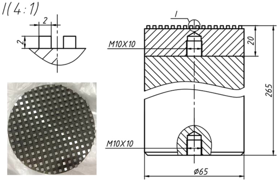
Magnetic pole size.
Polishing conditions
A parametric study was conducted to investigate the influences of current frequency, working gap, trough rotation speed, and workpiece rotation speed on the improvement rate of surface roughness and MRR. The experimental conditions are shown in Table 1. Four tests were carried out and the experiments were designed according to the one-factor-at-a-time rule, that is, in case of one parameter was varied, the other parameters were kept constant. The influence of the current frequency was studied in test 1. It can be seen that the fluctuation of MR cluster was not obvious when the frequency was greater than 4 Hz. As a consequence, the current frequency was varied from 1 to 4 Hz. The effect of the working gap was researhed in test 2. The working gap refers to the distance between the workpiece surface and the top surface of trough pad. Since the smallest hardening height of the MR fluid was 2.5 mm, the working gap was limited below 2.5 mm, namely, working gaps of 1,1.5, 2, and 2.5 mm were selected. In the previous experiments, it was found that MR fluid was thrown out of trough in case of trough rotation speed was faster than 30 r/min. Therefore, trough rotation speed was set between 5 and 40 r/min in test 3. In test 4, the workpiece rotation speed was controlled between 100 and 800 r/min to decrease the centrifugal effect during polishing. Finally, the material removal, improvement of surface roughness, and surface topography were investigated under trough speed of 30 r/min, workpiece rotation speed of 600 r/min, working gaps of 1 mm, and current frequency of 1 Hz. The detailed parameters are shown in Table 2.
Experimental conditions.

MR: magnetorheological.
Detailed parameters.

Sample
The square K9 glass workpiece with the size of 51 × 51 × 4.6 mm3 was used as the polishing sample. The K9 glass is used widely in optical industry because of its high transparency and high temperature resistance performance. 24 The initial surface roughness of K9 glass samples was Ra 580 ± 15 nm.
Measurements
The magnetic flux density in work area was measured by a tesla probe (model type: LZ-630 H) to investigete the performance of the developed groove magnetic pole. The dimension of the tesla probe was 1.8 ×3 mm2. The measuring error was 0.1% when measuring range was below 500 mT. To obtain the greastest possible magnetic field strength in the condition of ensuring trough rotate freely without any jam, a gap between the bottom of trough and the workpiece surface was set to 1, 1.5, 2, and 2.5 mm, respectively. The measure height is equal to the sum of nominal excitation distance from the top surface of the magnetic pole and the thickness of trough (16 mm), namely, the measure height was 17, 17.5, 18, and 18.5 mm from the pole top surface. A total of 17 points were arranged from the pole center to edge, with the interval of 5 mm.
The material removal of polished workpiece was measured by electronic scales (BSM-220) with the measuring accuracy of electronic scale of 0.1 mg. The MRR was calculated as shown in equation (3)

where Δm (mg) is the material removal amount, which was calculated by the initial material weight
The surface roughness (Ra) and form accuracy (PV) were measured using Zygo non-contact white light interferometer. We used the ×5 objective with the field of view of 1.88 × 1.41 mm2. We measured five points in processing region. The measuring points are shown in Figure 5. The improvement rate of surface roughness (SIR) can be calculated as shown in equation (4)
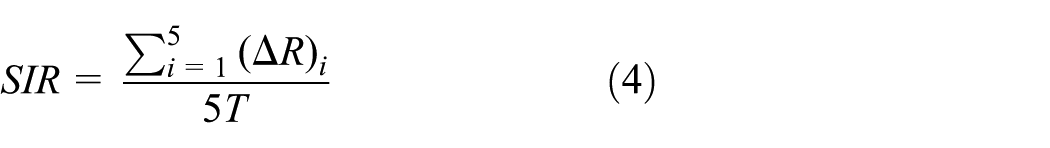
where ΔR (nm) is the improvement of surface roughness at measure point, which is equal to the initial surface roughness value subtracting the polished surface roughness value; T (min) is the polishing time; and SIR (nm/min) is the corresponding improvement rate of surface roughness.

Surface roughness measuring position.
Results and discussion
Magnetic sources
Figure 6 shows the distribution of magnetic flux density. Since the pole was cylindrical and head face was round with even distribution of grooves, the magnetic field distribution across the head face of pole can be predicted by measuring the diameter of a pole. In alternating magnetic field, the value and direction of current showed a periodic change with time, and the magnetic flux density was changing constantly between a peak value and valley value. Therefore, the measured results reflect the peak value (– valley value) at each measuring point. It was found that the produced magnetic field was the most powerful at the edge of the magnetic pole. The magnetic flux density gradually decreased from the magnetic pole circular to center. Moreover, the magnetic flux density decreased with the increase in excitation gap. The greatest value of magnetic flux density in working area was 363, 339, 310, and 290 mT, respectively, as the excitation gap changed from 17 to 18.5 mm.

Magnetic field distribution in polishing region.
As shown in Figure 7, a varying bowl-shaped MR cluster can be created under the alternating magnetic field. This MR cluster can better compensate the workpiece surface with different curvature in the process of processing, so that the processed surface is in full contact with the polishing tool and the overall polishing of the workpiece can be realized. The MR cluster presented a dispersing state and abrasives float above MR cluster when the force of the magnetic field was downward. The MR cluster was transformed into a contracting state while abrasives were converted into polishing surface as the force of the magnetic field turned upward. The variation of polishing MR clusters realized replacement of contact angle between abrasive particles and workpiece, which increased utilization of abrasives.

Movement change of MR cluster in alternating magnetic field.
Effect of parameters on polishing performance
Current frequency
The MRR and SIR in a tray-type MR polishing using LFAMF can be affected by parameters such as current frequency, working gap, trough rotation speed, and workpiece rotation speed. Figure 8 shows the influence of those parameters on the SIR and MRR. As shown in Figure 8(a), the corresponding SIR is 10.68, 9.63, 9.39, and 9.35 nm/min, and the MRR is 0.69, 0.63, 0.58, and 0.57 mg/min when the current frequency is 1, 2, 3, and 4 Hz, respectively. In this test, we observed that the fluctuating amplitude and range of polishing MR cluster increased with the decrease in current frequency. The greater the fluctuating amplitude, the more flexible the MR cluster, and the better the cross-cutting effect and stirring effect. With the decrease in frequency, the duration of the magnetic field strength showed an increasing trend while eddy current effects showed a decreasing trend, which increased the duration of abrasive action on workpiece surface. Therefore, the MRR and SIR increased with the decrease in magnetic field frequency.
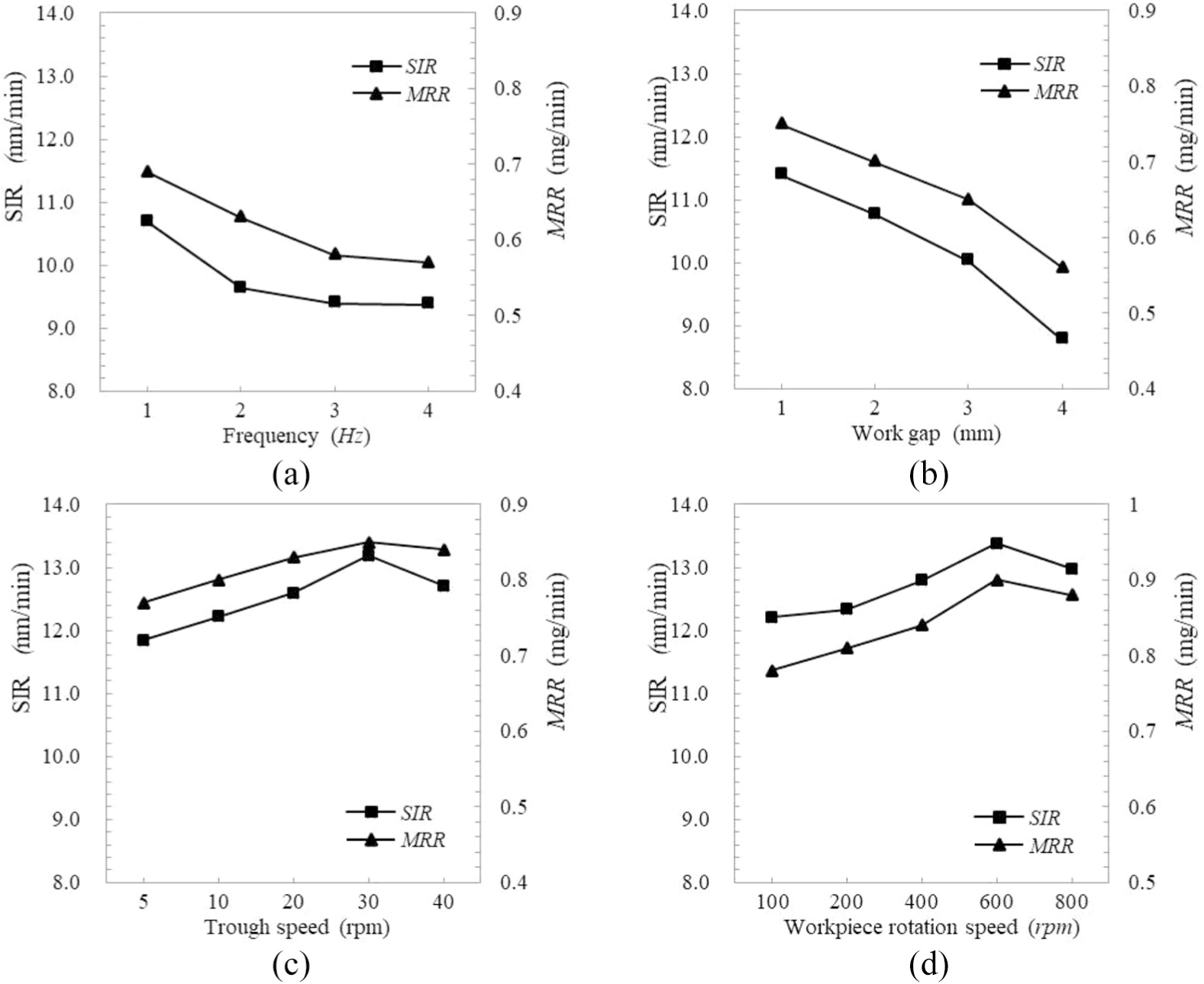
Effect of parameters on SIR and MRR: (a) frequency, (b) work gap, (c) trough speed, and (d) workpiece rotation speed.
Working gap
The effect of working gap on the SIR and MRR is shown in Figure 8(b). The results of test 2 show that the SIR increased from 8.78 to 11.39 nm/min and MRR increased gradually from 0.56 to 0.75 mg/min with the decrease in working gap. In the processing area, iron powders mixed with abrasives were hardened into an MR cluster of certain thickness under the action of alternating magnetic field. With the rotation of the polishing trough, the MR fluid of processing area kept flowing and constantly updated. The smaller the working gap, the higher the extrusion strength of MR cluster, the greater the shear force in contact with the workpiece surface, and the greater the MRR and SIR. In addition, the magnetic field intensity of the processing area decreased with the increasing working gap. Therefore, the strength of MR fluid hardening into MR cluster decreased, which resulted in the decrease in mutual friction force, MRR, and SIR.
In MR nono-polishing, the MR cluster has a high hardness due to the too small working gap, which will scratch the workpiece surface and affect the surface quality. In addition, a too small working gap will affect the flow of MR fluid, which to some extent hinders the update of abrasive and thus reduces the MRR and SIR.
Trough rotation speed
As shown in Figure 8(c), as the trough rotation speed increased from 5 to 30 r/min, the surface roughness increased from 11.84 to 13.19 nm/min, and MRR increased from 0.77 to 0.85 mg/min. The MRR and SIR in a polishing process is proportionally related to the relative speed between the workpiece and MR cluster. A greater trough rotation speed can produce a higher polishing efficiency. However, it was observed that the SIR was 12.71 nm/min and the MRR was 0.84 mg/min when trough rotation speed was 40 r/min. This is due to the fact that large amounts of MR fluid under the action of excessive centrifugal force would rush to the outer periphery of the trough if the trough rotation speed was too high. In consequence, the MR cluster passing through the processing area would become smaller, leading to reduction in MRR.
Workpiece rotation speed
Figure 8(d) shows that the SIR and MRR increassed with the workpiece rotation speed under present test conditions. As the workpiece rotation speed changed from 100 to 600 r/min, the SIR increased from 12.21 to 13.38 nm/min, and MRR increased from 0.78 to 0.9 mg/min. The SIR was 12.98 nm/min and the MRR was 0.88 mg/min when workpiece rotation speed was 800 r/min. The higher the workpiece rotation speed, the higher the relative motion speed, the more the contact times between the workpiece surface and the MR cluster in unit time. Moreover, the coagulation degree of MR fluid and frictional force acting on workpiece surface also became greater with the increase in workpiece rotation speed. It generates a higher resultant force coming from varying magnetic force and rotational frictional force, and then causing rapid material removal. However, when the workpiece rotation speed was 800 r/min, a mass of MR fluid spattered out of the processing area, which results in the decrease in MRR. Therefore, the workpiece rotation speed is usually controlled below 600 r/min.
MR fluid volume and abrasive
MR fluid is mainly composed of carbonyl iron powder with micron diameter, abrasive, and base carrier fluid. In this study, we made two kinds of MRF, namely, diamond abrasive MR fluid and cerium oxide abrasive MR fluid. The content of abrasives accounted for 8% of the total volume. Figure 9 shows the state of two MR fluids under electron microscope. As shown in Figure 9(a), the diamond abrasives had a relatively smooth surface, which presented a uniform distribution and adsorbed on iron powder. The mean diameter and Mohs hardness of diamond abrasives was 3.5 μm and 10, respectively. The Mohs hardness of cerium oxide abrasive was 7. The size distribution of cerium oxide abrasive was similar to 3–5 μm, which blends in base fluid, as shown in Figure 9(b). The viscosity of diamond abrasive MR fluid and cerium oxide abrasive MR fluid was 0.68 and 0.59 Pa·s, respectively. The MR fluid changed into MR cluster under the action of a magnetic field. Based on ferromagnetic fluid mechanics theory, high-intensity magnetic field on the non-magnetic polishing powder particles exhibited buoyancy effect, which made abrasive particles float on the workpiece surface, thus realizing the material removal. The mechanical removal effect was significant and the surface flow effect was not obvious in the condition of using diamond abrasive, while the surface flow effect was significant when cerium oxide abrasive was used.

SEM image of MR fluid: (a) diamond MR fluid and (b) cerium oxide MR fluid.
Figure 10 shows the effect of MR fluid volume and abrasive on SIR and MRR. Under the same test conditions, it was found that the SIR and MRR were approximately 1.32 times and 1.25 times of CeO2 in the case of using diamond abrasives. This is because the hardness of diamond abrasives and the viscosity of diamond MRF are greater than those of CeO2, so the diamond MRF produced a more significant mechanical cutting effect, and then obtained a higher polishing efficiency. However, the SIR and MRR increased with the increase in MR fluid volume, but the increased amplitude decreased from 700 to 900 mL, which indicates that the SIR and MRR almost remained unchanged when the MR fluid volume reached 900 mL.

Effect of MR fluid volume and abrasive on SIR and MRR.
The material removal, surface roughness, and surface topography were investigated under trough speed of 30 r/min, workpiece rotation speed of 600 r/min, working gaps of 1 mm, and current frequency of 1 Hz. As shown in Figure 11, the material removal reached 93.6 mg, the average value of surface roughness (Ra) decreased from 567.08 to 9.63 nm, and the flatness error (PV) of K9 glass decreased from 66.43 to 2.63 μm after 120 min of polishing. Figure 12 shows the 3D profile image of K9 glass surface before and after polishing. The surface roughness of K9 glass was improved to 11.71, 11.48, 7.7, 9.06, and 8.21 nm with five measurement points. It can be seen that the initial surface was rugged with scratch and dent, which was probably due to the previous machining process. After polishing, the surface became smooth, with the scratch and dent removed effectively. With the improvement in surface quality in MR polishing, the glass surface become more transparent, which is clearly shown in Figure 13. Experimental results demonstrate that the nano-polishing for glass surface can be realized by MR polishing using LFAMF.
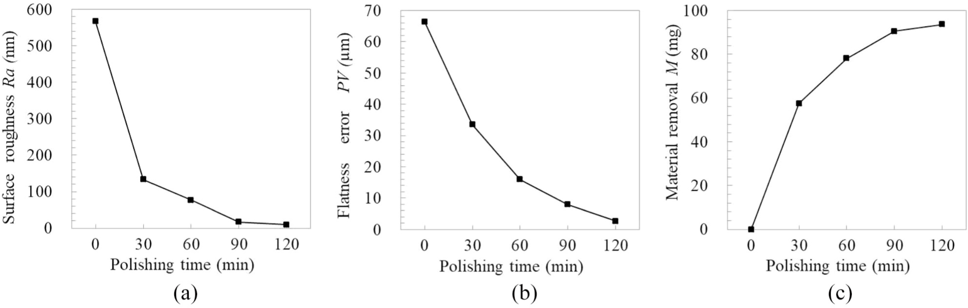
Change of surface roughness and material removal with polishing time: (a) improvement in surface roughness, (b) improvement in flatness, and (c) material removal.

3D profile images of polishing surface.

Photographs of polishing surface: (a) before polishing and (b) after polishing.
Conclusion
This study proposed a novel tray-type MR polishing process by LFAMF, and the conclusions can be summarized as follows:
A large, varying, bowl-shaped magnetic field could be generated using groove magnetic pole under LFAMF excitation. The most powerful magnetic field was produced at the edge of the magnetic pole. The magnetic flux density gradually increased from the magnetic pole center to circular, but decreased with the increase in excitation gap.
The SIR was 10.68, 9.63, 9.39, and 9.35 nm/min, and the MRR was 0.69, 0.63, 0.58, and 0.57 mg/min when the current frequency was 1, 2, 3, and 4 Hz, respectively.
As the working gap decreased from 2.5 to 1 mm, the SIR increased from 8.78 to 11.39 nm/min and MRR increased gradually from 0.56 to 0.75 mg/min.
The SIR and MRR increased with the increase in trough rotation speed when the speed was smaller than 30 r/min.
As the workpiece rotation speed changed from 100 to 600 r/min, the SIR increased from 12.21 to 13.38 nm/min, and MRR increased from 0.78 to 0.9 mg/min. When the workpiece rotation speed was 800 r/min, a mass of MR fluid spattered out of the processing area, resulting in the reduction of material removal.
In the case that diamond abrasives were used, the SIR and MRR were approximately 1.32 times and 1.25 times of CeO2.
Experimental results indicate that the proposed process can realize ultra-precision flat surface polishing. The MRR reached 93.6 mg, the surface roughness (Ra) decreased from 567.08 to 9.63 nm, and the flatness error (PV) of K9 glass decreased from 66.43 to 2.63 μm after 120 min of polishing.
Footnotes
Handling Editor: James Baldwin
Declaration of conflicting interests
The author(s) declared no potential conflicts of interest with respect to the research, authorship, and/or publication of this article.
Funding
The author(s) disclosed receipt of the following financial support for the research, authorship, and/or publication of this article: This work was financially supported by the National Key R&D Program of China [Grant No. 2017YFE0116900]; National Natural Science Foundation of China [Grant No. 51805159]; the Science and Technology Planning Project of Hunan Province [Grant No. 2019JJ50089 and 2018JJ3046].