
Abstract
On cutting coal, the cutting resistance of a shearer may change suddenly due to uneven coal quality. It can lead to sudden acceleration of the cutting motor, deceleration, overload shutdown, and even burnout of the motor. We studied the dynamic, static, and working characteristics of the torque shaft of a typical shearer to ensure that the torque shaft of the cutting unit can transfer the torque from the cutting motor to the gear reducer in the rocker under rated conditions and be turned off immediately to protect the motor in case of overload. A method of radial size design of the relief groove of torque shaft based on combining positive, reverse reliability with unloading coefficient has been presented, and the flow chart using this design method has been provided. The positive and reverse reliability torsional test of strength of the experimental torque shafts without relief grooves using three different materials and the measurement test of unloading coefficient of various types of relief grooves were performed. The experimental results obtained through our investigation achieve and even surpass the design purpose. More importantly, to serve the industry it is designed for, the torque shaft designed using this method has high reliability.
Introduction
Background
The cutting unit is the working mechanism of shearer. As shown in Figure 1, the function of the transmission device of the cutting unit is to transfer the power of the cutting motor to the picks of the drum, which consumes more than 80% of the total power of the shearer. 1 In the process of cutting coal, the cutting resistance of shearer will change suddenly due to uneven coal quality, especially due to the entrained gangue. The maximum cutting resistance may be several times to more than 10 times of the minimum cutting resistance. 2 The impact caused by these sudden changes of load will lead to sudden acceleration of the cutting motor, deceleration, overload shutdown, and even burnout of the motor. 3 Therefore, in a shearer with large mining height, the connecting shaft between the cutting motor and the reducer in rocker adopts a partially hollow elastic shaft, the position shown in Figure 1. This hollow elastic shaft is called the torque shaft. Its function is to effectively transfer the torque of the cutting motor under rated conditions and break immediately when the load exceeds the allowable value in order to protect the motor.

Transmission system of the cutting unit of drum shearer.
Figure 2 shows an actual photograph of the torque shaft used in the cutting unit of some shearers. It can be seen from Figure 2 that there are splines at both ends of the torque shaft, and there is an obvious groove near the left splines. This groove is known as the relief groove.

Torque shaft of the cutting unit.
When installed, the external spline, where the torque shaft is near the end of the unloading slot (at left in Figure 2), is connected with the internal spline at the end of the hollow hole of the cutting motor shaft in Figure 3(a). The external spline, where the torque shaft is far from the end of the unloading slot (at right in Figure 2), is connected with the internal spline in the bearing hollow shaft in Figure 3(b).The torque of the motor is transferred to the transmission system in the reducer of the cutting unit while working.
Installation position of torque shaft: (a) installation position in motor shaft and (b) installation position in gear shaft.
Literature survey
Torque shaft is one of the important parts in the cutting unit. However, considering that the structure is relatively simple compared with the whole machine, it does not attract extensive research. Liu Chunsheng et al. 4 and Jin Lihong et al. 5 conducted research on the working mechanism of a torque shaft. They established the dynamic simulation model of the transmission system of the cutting unit including the torque shaft, conducted the dynamic simulation analysis to the torque shaft by taking the specific parameters of the cutting part of the shearer as an example, analyzed the torsional characteristics of the torque shafts with different effective lengths under impact load, 6 and presented the functional design method of the torque shaft based on torsional static strength and fatigue strength. 7 Li-Juan Zhao et al.8,9 carried out statics analysis on the torque shaft of shearer for thin coal seam and simulated the working process of torque shaft clutch using ANSYS/LS-DYNA and ADAMS softwares. Furthermore, they calculated the variation law of stress and strain value of torque shaft at work and presented the parametric design method. 10 Ping Gao et al. 11 studied the material characteristics of the torque shaft of shearer of different models and different manufacturers. Xiaochao Li simulated the characteristic law of the load on the drum transferred to the torque shaft by MATLAB/Simulink and ADAMS. 12 Some scholars have carried out finite element analysis (FEA) on the relief groove of different shapes on the torque shaft and made suggestions on the selection of relief groove shapes by comparing the analysis results.13–18 The above research results reflect the characteristics and design ideas of the torque shaft from different perspectives, which provide a theoretical basis and reference for the new design method proposed in this article.
Scope and contribution of this study
Torque shaft with high reliability is the most important characteristic of a shearer to ensure proper energy transfer and protect the cutting motor. Accurate selection of the size and shape of the relief groove is the key to the design of the torque shaft. The working principle of the unloading tank is using the “crack technology” 19 to make the crack propagate to the tip of the notch and finally to realize the rapid and regular separation of the continuous interface of solid material at the bottom of the relief groove of the torque shaft. The contribution of this study is to propose a design of the relief groove of torque shaft based on combining positive, reverse reliability with unloading coefficient. The unloading coefficients of triangular, ladder, circular arc, and U-shaped relief grooves of different shapes, angles, and size ratios were measured through the torsional tests of several groups of specimens. The flow chart of determining the radial size of torque shaft based on combining positive, reverse reliability with unloading coefficient was obtained. The torque shaft designed by this method can transfer the torque of cutting motor effectively and protect the cutting motor reliably.
Analysis of the dynamic characteristics of the torque axis
Figure 4 shows one of the most widely used structures of the torque shaft in the cutting unit of the shearer, and it is a partial hollow elastic shaft.

Torque shaft structure diagram.
In Figure 4, the torque Tg from the cutting motor is input to L1 at the left end of the torque shaft, and energy is transmitted to the transmission system through L4 at the right end of the torque shaft. When the shearer works, the driving equation of the torque shafting is as follows 20

where TL is equivalent load torque at L4, Jg is equivalent moment of inertia at L4, JL is equivalent moment of inertia at L1, θ1 is angular velocity at L1, and θ2 is angular velocity at L4.
When the drum suddenly encounters gangue in the process of rotating, the sudden change of load increases the cutting resistance moment on the drum, which is equivalent to a TL superimposed step signal. The dynamic characteristics of the motor shaft were simulated, when the drum encounters larger gangue. For example, when the step of TL is larger, the hollow shaft section and the solid motor shaft are located at L1 of the torque shaft. The response curves shown in Figure 5 can be obtained.

Dynamic characteristics of torque shaft: (a) angular displacement of the motor shaft, (b) angular speed of the motor shaft, and (c) angular acceleration of the motor shaft.
Curve 1 in Figure 5(a)–(c) shows the relationship among angular displacement, angular velocity, and angular acceleration of the motor shaft with time, respectively, when the torque axis at L1 was hollow. Curve 2 represented their relationship, when the torque axis at L1 was solid. The mathematical relationship of the three parameters is differential in turn. It can be seen in Figure 5(c) that the extreme value of curve 1 is obviously smaller than that of curve 2. Therefore, the hollow shaft can play a role of vibration reduction and overload protection for cutting motor. Therefore, the hollow shaft section is the key for the torque shaft to reduce the vibration of the transmission system of the cutting part.
The static analysis of the torque shaft
During operation, the torque shaft transmits the rotating mechanical energy from the cutting motor to the gear system in the rocker. No other torque input/output parts are installed in the middle of the torque shaft, so the torque diagram shown in Figure 6 can be obtained.

Torque diagram of the torque shaft.
It can be seen from Figure 6 that the torque is the same at every point on the shaft. Therefore, it is the material, shape, and size of the torque shaft that determines whether the torque shaft can act as overload protection, that is, whether the cutting resistance moment can be broken when the cutting resistance moment increases.
The calculation method of shear stress at the hollow circular shaft with outer diameter d and inner diameter di (at the relief groove) is as follows

In Figure 7, the outer diameter at the intersection of L1 and L2 at the left end of the torque shaft is d, and the diameter value is the smallest in all the outer diameters on the shaft, and this position on the shaft is the hollow; so, the groove experiences the maximum stress in the entire shaft. The shape of the ring groove may have stress concentration, and it is the most easily twisted place on the shaft; so, it is called the relief groove of the torque shaft. The static simulation results of stress distribution on torque shaft are shown in Figure 7 by FEA.

Stress distribution in the torque shaft.
It can be seen from Figure 7 that the stress at the groove is very concentrated and much larger than in the surrounding areas; therefore, proper design of the relief groove is the most important factor in determining whether the torque shaft can carry out effective overload protection for the cutting motor of shearer.
When the rotation angle of the torque shaft
Reliability design of relief groove for torque shaft
Basic idea of reliability design of torque shaft
When the cutting motor works under the rated torque TN, the torque shaft should transfer the energy to the drum, and the torque shaft must be twisted off at relief groove before the cutting motor reaches the blocking torque Tst (that is 2.2 times of the rated torque TN). It can be seen that the reliability design of torque shaft is not only the probability design that the load stress is greater than the material strength but also the probability design that the load stress is less than the material strength.
In the process of transferring torque, the external load will produce shear stress τ on the shaft and the material of the torque shaft has a certain shear strength τs. These two values follow the normal distribution in the normal working process of the shearer. If

If the power of the cutting motor is P, the inner diameter of the torque shaft can be determined as di by the tool that pulls it out of the shaft. The calculation method of shear stress at the outer diameter d of relief groove has been obtained by equation (2).
Positive reliability design of torque shaft strength
Here, the positive reliability design is the probability design that the torque shaft does not break when the rated torque works. When the coal mining machine is operated at a rated power, the value of the cutting resistance moment
The dangerous section of the elastic torque shaft, that is, the section of the relief groove, is the hollow shaft section, and the value of the torsional cross-section coefficient

Because both di and d follow normal distribution, the value of the torsional cross-section coefficient,

In equation (6), the standard deviation of the inner and outer diameters of the dangerous section of the torque shaft can be obtained from the statistical data of the manufacturing tolerance,
25
From equations (5) and (6), the mean and standard differences in shear stress on the torque shaft can be calculated as follows


Assuming that the mean value and standard deviation of the shear strength of the material used in the torque shaft are
The statistical values of the outer diameter, inner diameter, and standard deviation of the dangerous section and the mean value and standard deviation (which can be calculated as 8% of the mean value 26 of the shear strength of the material) are substituted into equation (9), and equation (10) can be obtained as follows

The mean value
Reverse reliability design of the torque shaft strength
Equations (9) and (10) can be expressed as “the reliability that the torque shaft cannot be twisted off under the rated torque of the cutting motor.” However, when the torque on the torque shaft is 2.2 times of the rated torque, TN, of the cutting motor, it must be twisted off immediately. The concept of reliability is used to explain that “the reliability that the torque shaft can be twisted off when the torque on the torque shaft is 2.2 times the rated torque of the cutting motor,” that is, “the reliability that the torque shaft can be twisted off when the stress is greater than the strength,” which is called the reverse reliability design of the torque shaft strength. The connection coefficient of “the probability that the stress is greater than the strength” can be obtained by exchanging the mean and standard deviation of the stress and strength in equation (3)

The reverse reliability design of torque shaft strength is still the problem of strength and stress. Therefore, the torsional section coefficient, mean value, and standard deviation of the cross section of the relief groove are still the same as those in equations (4), (5), and (6), respectively. Assuming that the standard deviation of the locked rotor torque of the motor is

From this, the mean value and standard difference of the maximum shear stress on the elastic torque shaft can be obtained as follows

Assuming that the mean value and standard deviation of the shear strength of the material used are

Same as the forward reliability design of the torque shaft strength in section “Positive reliability design of torque shaft strength,” the mean allowable maximum torque of the cutting motor is two times of the rated torque. At this time, the standard deviation of the blocking torque of the motor is 10% of the mean maximum torque. Then, equation (16) can be obtained by replacing the statistical value of the mean value and standard deviation of the outer and inner diameter of the dangerous section and the mean value and standard deviation of the shear strength of the material with equation (15) as follows

Similarly, for the selected torque shaft material, the rated power of the cutting motor, and the reliability coefficient,
Design results and reliability analysis
Equations (10) and (16) are similar multinomials with the same exponents. Squaring both sides of equations (3) and (11), we arrive at different solutions for the outer diameter in equations (10) and (16). The outer diameter value, d, in equation (10) is obtained when the reliability coefficient is

Reliability design for the theoretical size of the relief groove.
It can be seen from Figure 8 that when the value of reliability coefficient is 0, the size of the outer diameter d of the cross section of the relief groove is the same as that of the inner diameter of the cross section of the relief groove, and that the diameter d increases rapidly with the increase of the reliability coefficient
Unloading coefficient of relief groove
The value of

Various shapes of relief grooves: (a) triangular groove, (b) ladder groove, (c) circular arc groove, and (d) U-shaped groove.
For torque shafts with the same outer diameter but different shapes of relief grooves, their torque values are different when they are twisted off. For torque shafts with the same outer diameter but with the same shape and different size of the relief groove, their torque values will be different when they are twisted off. The influence of the shape and size of the relief groove on the twisting characteristics can be expressed by the unloading coefficient

where
Experimental setup
Experimental scheme
The experiment includes two parts: the reliability test of torque shaft strength and the unloading coefficient test of the relief groove.
If the power of the shearer is different, the size of the torque shaft required is different, and, therefore, the shape of the relief groove required on the torque shaft is also different. The actual length of the torque shaft varies from 1 to 1.4 m, and the diameter dimension varies from 50 mm to more than 90 mm. Assuming that the subscript y is used to represent the original dimension parameters of the actual torque shaft and the symbol s represents the relevant dimension parameters of the test piece, the matching relationship between the size and the shape of the relief groove of the test piece and the actual torque axis can be determined according to the following calculation rule. 27 The dimensional matching relationship between the test piece and the actual torque shaft can be derived from geometric similarity. Through the torque shaft structure diagram of Figure 4, the dimensional relationship between the two should satisfy the following formula

When the size ratio of the specimen to the relief groove of the actual torque shaft is kept at
From equation (2), for a selected material with allowable stress, the matching relationship between the power ratio of the specimen and the motor selected by the actual torque shaft is as follows

According to equation (19), for the torque shaft twisted off by strength failure, the power needed for failure is proportional to the cube of the diameter ratio of the specimen to the actual torque shaft and proportional to the rotational speed and the ultimate stress of the material’s shear strength. Since the torque shaft is mainly destroyed by shearing force because of excessive torque, and the stiffness has little effect on the destruction of the torque shaft, the radial size and shape of unloading groove are considered mainly in selecting the specimen. 11 At present, most of the relief grooves for torque shaft of shearer are circular arc and U-shaped, and a small number of triangle and ladder grooves are also used. Therefore, five types of torque shafts are selected as specimens for this experimental research: (a) without any relief groove using different materials, (b) with circular grooves of different sizes and fillets, (c) with triangular grooves of different sizes and angles, (d) with ladder grooves of different sizes, and (e) different angles and U-shaped grooves of different sizes but same bottom width. Taking the external dimensions of the torque shaft used in MG500/1200-WD shearer as a reference, the size was reduced by 3.5 times. Its overall appearance, dimension, and structure of the different specimens are shown in Figure 10.
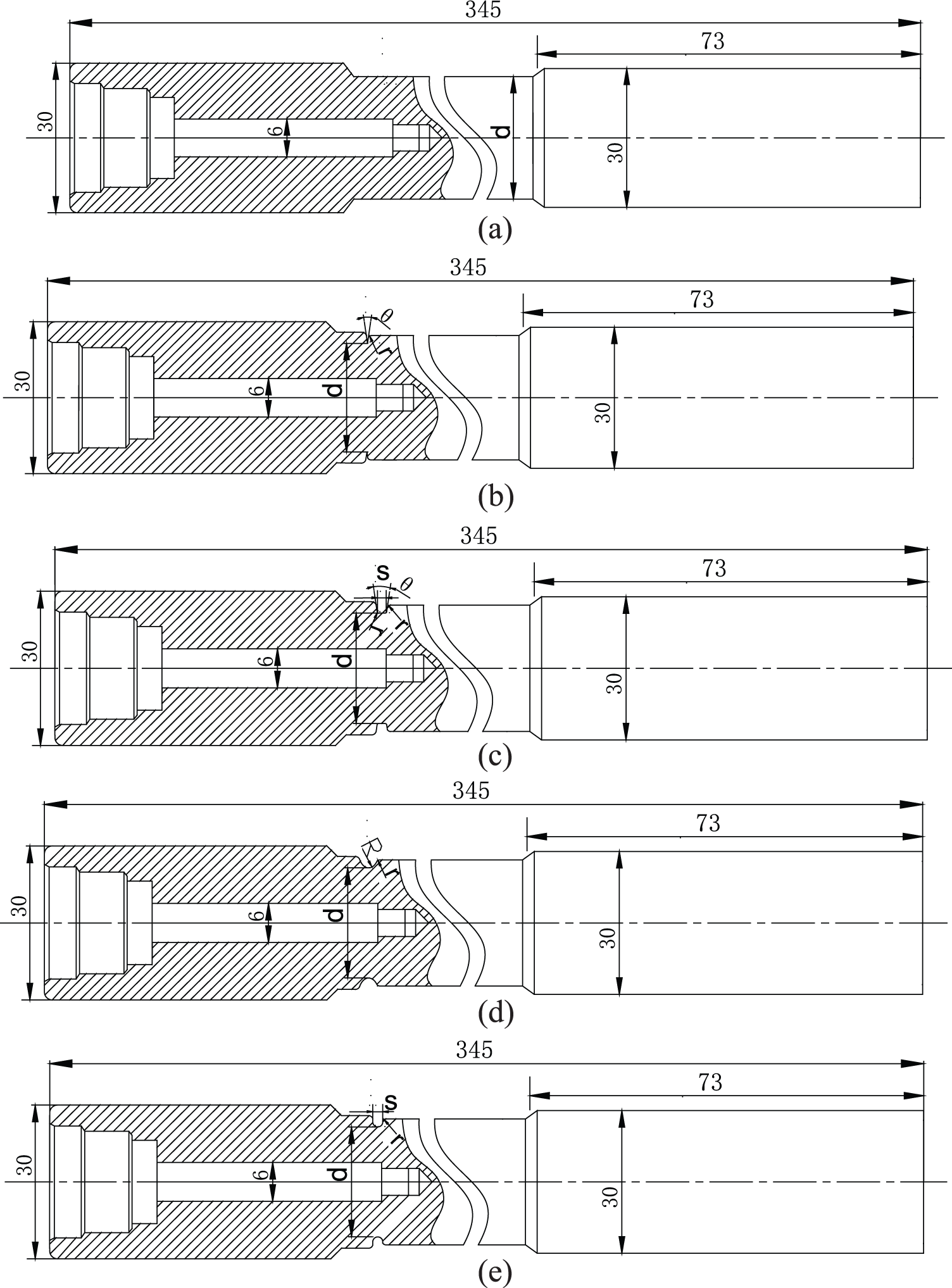
Structural diagrams of different types of torque shafts for experiment: (a) torque shaft without any relief grooves, (b) torque shaft with triangular grooves, (c) torque shaft with ladder grooves, (d) torque shaft with circular arc grooves, and (e) torque shaft with U-shaped grooves.
The value of diameter d of the specimen without any relief groove is calculated according to the reliability design method based on combining positive with reverse reliability presented in this article. The value of diameter d of the specimen with relief groove is the same as that of the corresponding specimen without any relief groove. The specific shape parameters of the four types of relief grooves are shown in Table 1.

where T is the torque value when the experimental torque shaft without the relief groove is twisted off, and TX is the torque value when the inner diameter of the relief groove is the same as the diameter
Torque values of test shaft twisted off (N m).

In the experiment, the torsional experiments of the specimen without relief groove were first carried out, and the torque values of T were obtained when they were twisted off. Then the torsional experiments of the specimens with relief groove were carried out, and the torque values TX were obtained with different shapes and parameters when they were twisted off. Finally, the unloading coefficients of relief groove with different shapes and sizes can be obtained using equation (20).
Selection and preparation of experimental samples
Based on the reliability design and analysis of the torque shaft strength in section “Design results and reliability analysis,” according to the scaling factor mentioned above/before, the specimens’ inner diameter di and outer diameter d were calculated as 6 and 13 mm, respectively. At present, A3 and 40Cr are more used in torque shaft materials. In order to increase the effectiveness of the experimental results, the specimens were made of A3, 45, and 40Cr steel. The tensile shear test shows that the shear strength limits of the three materials are 456.8, 556.8, and 630.1 MPa, respectively. The machining accuracy of the machine tool used for processing the specimens was calculated according to the standard deviation and manufacturing tolerances discussed in sections “Positive reliability design of torque shaft strength” and “Reverse reliability design of the torque shaft strength.” The strength reliability of the specimen can be calculated from equations (8), (10), and (16). The torque ranges of the specimens from the three materials were 169.4–207.0 N m, 206.5–252.3 N m, and 233.6–285.4 N m, respectively. These shafts’ pictures are shown in Figure 11.

Materials of specimens used in the experiment: (a) specimens without any relief grooves and (b) specimens with relief grooves.
Selection of experimental equipment and system design
The experimental device shown in Figure 12 was used in the experiment. One end of the tested torque shaft is connected with the output end of the motor shaft through the coupling, and the other end is connected with one end of the torque sensor through the coupling. The other end of the torque sensor is connected to the output of the CZ-50 magnetic powder brake (the device at the right end of Figure 12(a)) through a coupling. The motor, torque sensor, and magnetic powder brake are fixed on the dovetail base through the specially designed motor base, sensor support, and magnetic powder brake base, respectively. In order to prevent overload damage to the motor, the experimental platform is equipped with motor overload power off protection device. In order to prevent the torque shaft from flying out of the testbed when the torque shaft is cut out of the test, a safety cover is installed on the outside of the test shaft. The selected motor model was Y200L-4, and its maximum torque was 428.8 N m. The maximum torque of the selected motor and the rated torque of the magnetic powder brake are more than 285.4 N m which is the maximum torque in all the specimens to damage. This torque can meet experimental requirements. The rated torque value of the magnetic powder brake is 500 N m, connected to the WLK-3A controller (the device at the left end of Figure 12(b)) through the control line. The required torque value can be obtained by adjusting the knob of the controller. The torque value generated by the magnetic particle brake is measured using an ORT-803 digital torque sensor. The measured torque value of the sensor is transmitted to ORT-N1 intelligent torque meter (the device at the middle end of Figure 12(b)) through the data wire. The measured torque value can be displayed in real time through the display screen on the torque meter. The torque meter has the function of recording peak value, and the data in the torque meter can be displayed and stored in the computer through RS232 interface line.

Structural diagram of the experimental station: (a) mechanical part device and (b) test system device.
At the beginning of the test, the test torque shaft without the relief groove was first installed as shown in Figure 12. The magnetic powder brake was set to zero so that it does not produce braking torque. Then the motor was started and the braking torque of the magnetic powder brake was increased gradually. The torque on the test shaft, especially in the event of fracture, can be read out by the torque monitor or the computer monitor connected to it. The tested torque shaft was replaced and retested to obtain the torque data when each shaft broke. When the instantaneous increase of the load of the drum is transmitted to the cutting motor, it reaches the blocking torque so that the torque shaft of the cutting part is broken before it burns out. This is the process for the torque shaft to protect the cutting motor. The load added in the test needs to be similar to the fracture of the torque shaft when the torque shaft is actually working, so the loading mode of the sudden change load is selected for the magnetic powder brake in the test. Considering the maximum torque of the motor used in the experiment, the braking torque applied to the magnetic powder brake is an impulse signal of 300 N m.
Experimental results and discussion
Reliability test of torque shaft strength
The photo of the test shaft broken is shown in Figure 13, and the torque value of the test shaft measured by the experiment is shown in Table 1.

Test shaft without relief groove twisted off.
From the experimental data shown in Table 1, it can be seen that the torque shaft of the tested torque shaft is not only within the designed torque value range but also concentrated when the torque shaft is twisted off. Therefore, the design method based on positive and reverse reliability for torque shaft presented in section “Design results and reliability analysis” can fully realize the purpose of transmitting torque, especially for the protection of the cutting motor. Moreover, it has a very high degree of reliability. At the test motor speed of 1470 r/min selected for the experiment, the average cutting power that can be transmitted during normal operation (i.e. the rated power value of the supporting cutting motor of the tested shaft) is 14.5, 17.7, and 20.0 kW, respectively. At the same time, the motor power which should be matched according to the principle of geometric similarity, motion similarity, and dynamic similarity can be calculated using equation (19), and the value of the torque axis reliability under the machining accuracy and the selected material can be calculated according to the method described in section “Design results and reliability analysis.”
Test for unloading coefficient of relief groove
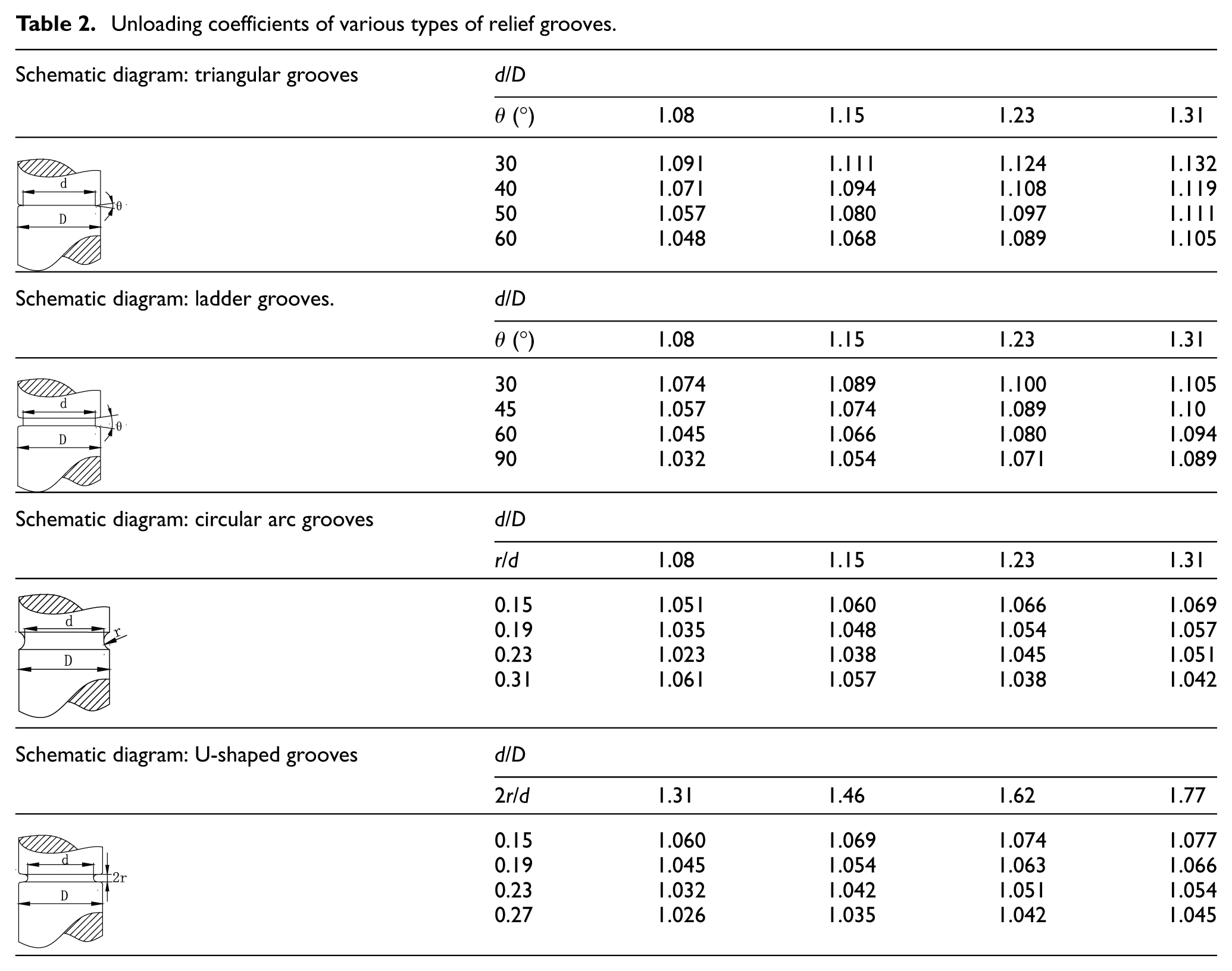
The photographs of the torque shaft with relief groove twisted off during the test are shown in Figure 14. The unloading coefficients of the torque shaft measured according to the different shape parameters measured by equation (20) have already been shown in Table 2.

Torque shafts with relief grooves twisted off: (a) triangular grooves, (b) ladder grooves, (c) circular arc grooves, and (d) U-shaped grooves.
Unloading coefficients of various types of relief grooves.
Comparing Figures 13 and 14, it can be seen that the torque shafts with relief grooves are not only twisted off at the unloading grooves but are also nearer the fracture surface of the specimens with relief grooves than the one without the relief grooves. When different types of relief grooves are twisted off, the degree of neatness of the sections are also different, and the sections of triangular grooves are the most uniform provided the same material is used.
From the unloading coefficients of the four shapes of relief grooves shown in Table 1, it can be seen that the unloading coefficients of triangular grooves are the largest and the unloading coefficients of circular arc grooves are the smallest under similar internal to external diameter ratios. This is consistent with the most intensely concentrated stress at the bottom of the triangular groove and the small stress concentration in the circular groove. Similarly, the faster the boundary streamline turns and unloads, the more obvious the unloading effect in the same shape. Taking the triangular groove as an example, it can be seen that the smaller the angle θ is, the larger the unloading coefficient is, that is, the relief grooves are more easily twisted off at the same torque and the bottom diameter of the relief groove. For the ladder groove, even if the width of the bottom of the slot is too large, it will not show obvious unloading characteristics. The width of the bottom of each ladder groove in the test was 2 mm.
Use of results
In summary, the steps of determining the radial dimension of the torque shaft using the reliability design method of the relief groove of torque shaft based on combining positive, reverse reliability with unloading coefficient can be expressed as a flow chart as shown in Figure 15.

Flowchart for the radial size calculation of the torque shaft.
Conclusion
The mechanical analysis and reliability design of relief groove for torque shaft of shearer were studied, and the main conclusions are summarized.
The torque shaft can play the role of damping, that is, of protecting the transmission system in the rocker arm. Considering that the stress is the largest in the relief groove of the torque shaft, proper design of the relief groove is the key to overload protection of the cutting motor.
A method of radial size design of torque shaft based on combining positive with reverse reliability was presented. The reliability torsional test of strength of the experimental torque shafts without relief groove using three different materials were carried out, which verified the correctness of this design method.
The concept of unloading coefficients was presented. The value of unloading coefficient is related to the angle and size ratio of the relief groove and the method of calculating and testing unloading coefficient were obtained. The unloading coefficients of triangular, ladder, circular arc, and U-shaped relief grooves of different shapes, angles, and size ratios were measured through the torsional tests of several groups of specimens.
The flow chart of determining the radial size of torque shaft based on combining positive, reverse reliability with unloading coefficient was obtained. The designed torque shaft using the proposed method was found capable to realize the energy transfer of the cutting motor under the rated parameters and be twisted off before the cutting resistance was too large to protect the cutting motor. The torque shaft designed by this method was found to have high reliability.
The method of radial size design of the relief groove of torque shaft, based on combining positive, reverse reliability with unloading coefficient, and the unloading coefficients of four shape relief grooves for torque shaft measured by experiments in this article, can provide theoretical basis and technical reference for the design of the torque shaft of shearer in engineering.
Footnotes
Handling Editor: James Baldwin
Author contributions
The manuscript was written through equal contribution by both the authors. Both have given approval to the final version of the manuscript.
Declaration of conflicting interests
The author(s) declared no potential conflicts of interest with respect to the research, authorship, and/or publication of this article.
Funding
The author(s) disclosed receipt of the following financial support for the research, authorship, and/or publication of this article: the authors thank the support of The Project of the Basic Research on the Application of Shanxi Province (grant no. 201801D221215).