
Abstract
This article introduces the operating principle and structural characteristics of the electromechanical integrated toroidal drive system. For its inner and outer toroidal double-stator structure, the equivalent current method is applied to calculate its spatial magnetic field, which is produced by the sector cylindrical magnetic teeth and the helical variable cross-section magnetic beam. For the application of the equivalent current method in the modeling of the magnetic field, an effective correction method is proposed. The flux density calculation models for the main magnetic field in the inner and outer air gaps are established under the unified coordinate system, and the analytical expression of magnetic field distribution in spatial air gap is deduced. Finally, the feasibility of the mathematical analytical model is verified by comparing the analytical calculation results with the finite element simulation results. The influences of the main structural parameters on the distribution of the air gap magnetic field and the torque are analyzed, which lay a theoretical foundation for the optimal design of the electromechanical integrated toroidal drive system.
Keywords
Introduction
In many drive arrangements, the output force and torque at low speed are required. It is a common method to connect a servo motor with a mechanical gear reducer to meet the requirements. 1 This makes the whole drive system more complex, and the mechanical gear reducer reduces the efficiency of the whole drive due to the mechanical friction between the gears. Meanwhile, the dynamic system causes additional vibration and noise, which reduce the service life of the whole system.2,3 Therefore, the composite drive system with characteristics of electromechanical integration, contactless, and drive ratio has become one of the important design directions of the drive system.
The electromechanical integrated toroidal drive is a new type of generalized compound drive. It is developed by introducing electromagnetic and control elements into a planetary worm drive.4–6 It realizes the advantages of large reduction ratio and contactless electromagnetic meshing, namely, it combines electromagnetic and mechanical drive effectively. It also can transmit large torque in a limited space with higher power density and power index. Besides the fields of vehicle and military devices which require compact structure, it also has broad application prospects in the fields of high control requirements such as robots and aerospace engineering.7,8 To date, a great deal of research has been performed on the structural analysis, kinematics principle model of an electromechanical integrated toroidal drive.9,10 The output of the toroidal drive is achieved by the spatial planetary gear with spiral magnetic field, which is created by the outer stator and the central worm stator. The planetary carrier as an output rotor realizes the energy conversion. It is important to analyze the inner and outer air gap magnetic field between the planets and the two stators, because the results of the air gap magnetic field analysis not only affect the calculation of the torque, noise, and other characteristics, but also directly influence the control performance of the toroidal drive.11,12
Recently, the magnetic field analysis of an electromechanical integrated drive is mainly based on the analysis methods of various motor magnetic fields. Among them, the equivalent magnetic circuit method is a traditional method of air gap magnetic field analysis. The method was used to analyze and calculate the electromagnetic torque of an electric/mechanical hybrid four-degree brushless direct current (DC) torque motor. 13 The accuracy of the calculated cogging torque is verified by experiments. It should be noted that the disadvantage of this method is that the equivalent magnetic circuit model would be more complex with an irregular structure. 14 Compared with the equivalent magnetic field method, the subdomain technique solves Maxwell’s equations by determining the boundary conditions, and it can obtain the analytical solution in the form of Fourier series, which can achieve the precision in the finite element method. 15 In 2009, French scholars took the surface-mount permanent magnet motor with integer slot winding as the research object and established a more accurate subdomain model. The model performs Fourier expansion on the vector magnetic position distribution of all slot openings in a pole pitch period, which is in accordance with real physical conditions, thus obtaining a higher computational precision.16–18 However, for varying cross-section drives, due to the complexity of the structure, the change of the magnetic field is related to the three coordinates of the field point, which makes the solution of Maxwell’s equations greatly difficult. 19 The equivalent current method is based on Ampere circulation hypothesis; according to the Biot–Savart law, the magnetic field intensity at any point outside the permanent magnet can be obtained by the integral method. Since the solution of the analytical method depends only on the path of the equivalent current, the complexity of the structure of the drives can be neglected. Therefore, for the drives with complicated spatial structures, the equivalent current method is a desirable method for calculating the magnetic field. In the study by Liu, 20 the distribution of the magnetic field produced by rectangular permanent magnets in space is calculated systematically, and the accuracy of the analytical calculation is verified by experiments. For the linear synchronous motor with slotted permanent magnet, the positioning torque and output thrust of the motor are optimized by considering the magnetizing current of the cogging effect. 21 The optimization result does not only reduce the positioning torque of the motor, but also greatly increase the output thrust.
In this article, the method of calculating the equivalent current required for the mathematical modeling of the permanent magnet tooth magnetic field of the toroidal drive is presented. And a correction coefficient is introduced to reduce the error of the mathematical model. In addition, for the complex double-stator toroidal space structure, the mathematical analysis model of the magnetic flux density of the inner and outer air gaps is established using the Biot–Savart theorem under a unified absolute coordinate system. The validity of the mathematical analysis model is verified by finite element simulation. Finally, the face width angles of the worm stator and the outer stator and the air gap values of important structural design parameters are selected as design variables, and their effects on air gap magnetic field distribution and output torque are discussed. The research results can provide guidance for further optimizing the design of the toroidal drive structure.
Operating principle of the electromechanical integrated toroidal drive
The basic structure of the electromechanical integrated toroidal drive is shown in Figure 1. Its main structure consists of (1) central worm stator, (2) planet gears, (3) outer stator, and (4) planet carrier rotor. The central worm is formed by laminating silicon steel sheets, and its surface is machined with spiral armature winding slots. A certain number of armature coils are placed in the slots to generate a spiral magnetic field. The planet gears are made of aluminum, and the N–S pole permanent magnets are evenly distributed on its cylindrical surface. The planet gears are fixed with the planet carrier rotor between the central worm and the outer stator. When the planet gears rotate, the planet carrier rotor rotates, that is, the planet carrier rotor is the output shaft of the toroidal drive system. The outer stator consists of several spatial helical beams made of permanent magnets. The N and S poles are embedded in the outer stator bracket evenly, which is used to guide the planet teeth to move along the corresponding trajectory.

Structure of the electromechanical integrated toroidal drive.
Since the planet gears are installed between the central worm stator and the outer stator according to certain electromagnetic engagement relationship. 16 When three-phase alternating currents are applied to the worm armature winding, the corresponding rotating helical magnetic field will be generated on its surface. According to the electromagnetic theory, the permanent magnetic teeth on the planet gears are subjected to tangential force, which makes the planet gear teeth move along the circular helix outside the central worm. Simultaneously, the planet gears are driven to rotate around the central worm axis with the planetary carrier. Because the planet gears and the planet carrier are connected, the output torque is realized. The planetary carrier rotor rotates at a certain reduction ratio and maintains a quasi-synchronous relationship with the rotating magnetic field. The electromechanical integrated toroidal drive combines the advantages of the planet worm drive with a large reduction ratio and frictionless gear transmission, which realizes the organic combination of mechatronics and electromagnetism.
Establishment of the magnetic field model with equivalent current
Calculation of equivalent current
For a single permanent magnet, radial magnetization is applied to achieve saturation. The magnetic motive force can be obtained as follows

where µ0 is the absolute permeability, µr is the relative permeability, Br is the retentivity, and t is the permanent magnet thickness. In addition, according to the Ampere loop hypothesis, the corresponding current coil is equivalent on the surface of the planet teeth. The equivalent current is Im and the magnetic motive force of the permanent magnet tooth is

where N is the number of turns of the current coil. By substituting equation (1) into equation (2), the equivalent current can be obtained, where D = t/N is the diameter of the equivalent current coil

Establishment of the magnetic field model
In order to verify the feasibility of the mathematical modeling of the magnetic field applied to the drive by the abovementioned equivalent current, the magnetic field of a single planetary gear is selected for calculation. The structural analysis model is shown in Figure 2. Figure 2(a) shows the meshing of a single planet gear with the inner and outer stators, and Figure 2(b) shows the equivalent current model of a single permanent magnet tooth on the planet gear.
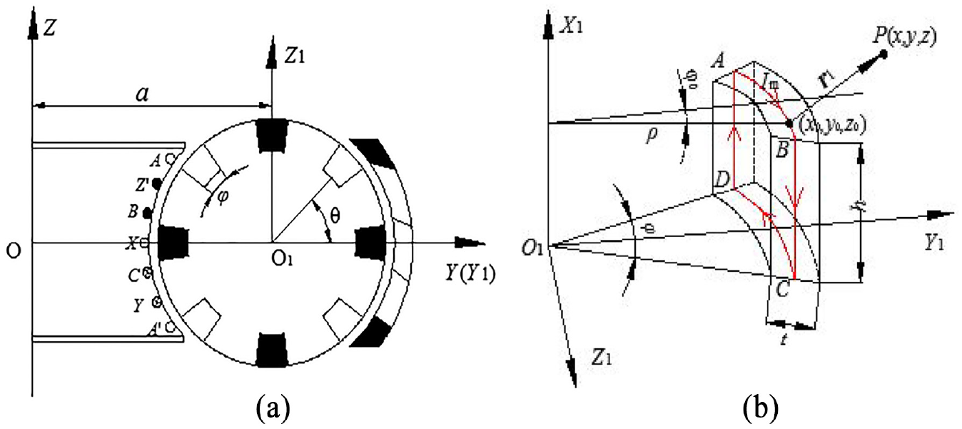
Analytical model of the planet gear: (a) meshing of plane gear teeth and (b) equivalent current model of a single tooth.
Taking the field source coordinates of any point on equivalent current coil ABCD as (x0, y0, z0) in Figure 2(b) and combining with Figure 2(a), the trajectory equation of equivalent current coil of any permanent magnet teeth on the planet gear in the O-XYZ coordinate system can be established as follows

where n represents the nth permanent magnet tooth on the planetary gear, φ0 is the angle between the field source point and the XY plane, a is the center distance between the worm and the planet gear, ρ is the radius of the field source point, and θ is the angle between the adjacent permanent magnet teeth.
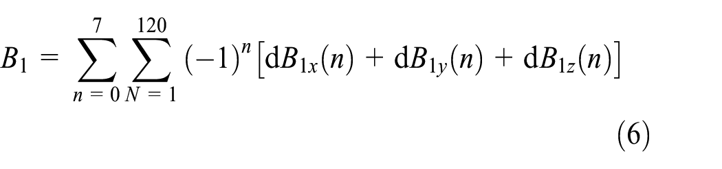
According to the Biot–Savart law, the components of flux density at any spatial point P for a single-turn coil under a coordinate system can be obtained as dB1x, dB1y, dB1z. The flux density component produced by a single planet tooth at any point P under a coordinate system can be obtained by superimposing dB1x, dB1y, and dB1z along the direction of the thickness t of planet teeth. The magnetic flux density produced by a planet gear at any point can be obtained by superposition of the total eight planet teeth at each axis. The total magnetic flux density can be expressed as follows


As shown in Figure 2, the trajectory of a single-turn coil is continuous but not smooth and cannot be integrated continuously. The equivalent current coil needs to be divided into four sections of smooth current to superposing as shown in equation (7). Among them, the AB segment and the CD segment differ only by one tooth height h, and the BC segment and the DA segment differ only by one tooth width angle φ. The expressions of the AB and BC segments are given below
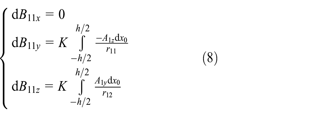

where t1 = (φ0 + nθ),

According to the above mathematical model, the calculated results are compared with the finite element simulation results as shown in Figure 3. The main structural parameters of the planet gear are given in Table 1.

Comparison of planet gear flux density.
Main structural parameters of the planet gear.

According to the structural parameters shown in Table 1, the magnetic flux density distribution of the planetary gear is obtained by simulation and compared with the calculation results of the analytical model. The results are shown in Figure 3.
From the comparison shown in Figure 3, it can be seen that the results of the equivalent current analytical model are different from those of the finite element simulation at the valley of each planet tooth of the planet gear. This is because the magnetic field generated by the current coil is inversely proportional to the square of radius (r2) of the field source. When r exceeds a certain effective distance, the magnetic field will decay rapidly. Because the distance between the AB and CD symmetrical coils exceeds their effective distance, rapidly attenuating the magnetic field of the two coils at the center of symmetry leads to the decline of waveform follow-up at the valley. In order to reduce the error between the mathematical model established by the equivalent current method and the finite element simulation, a correction coefficient is constructed to reduce the error caused by the coil distance.
For a single tooth, the magnetic field density decreases rapidly in U shape, and a Gaussian distribution function is used to correct it. For a planet gear, a Gaussian distribution function with periodic distribution is constructed to correct the multi-teeth. However, the Gaussian distribution function is a non-periodic function. By narrowing the boundaries on both sides, the function converges to zero in a range of tooth width angle, and then a Gaussian distribution function with period is obtained by superposition. Because the boundary range of the Gaussian distribution function amplitude approaching 0 is 6σ, the reduction ratio coefficient of the period can be obtained as λ = 3nσ/π. According to the ratio of the distance between the coils and the effective distance, the amplitude-increasing ratio coefficient can be obtained as ξ = Rφ/ε, where ε is the effective distance (the value is about 3 mm according to the simulation results). Considering the relationship between the structural parameters of the planet gear, the correction coefficient KC is obtained

where n = 0, 1, …, 7 corresponding to the eight planet teeth of the planet gear, respectively. The corrected air gap magnetic density distribution of a planet gear is shown in Figure 4. It can be seen from the figure that the analytical results of equivalent current have been significantly improved in the waveform consistency, and the modified equivalent current analytical model is effective.

The comparison result of planet gear flux density after correction.
Calculation of the space air gap magnetic field
Calculation of the inner air gap magnetic field
The inner air gap magnetic field is the coupling magnetic field produced by worm armature winding and the magnetic teeth of planet gears. The planet gear train can be obtained by coupling four planet gears with the planet carrier. Rotating the established single planet gear magnetic field model around the Z coordinate axis three times and superimposing, the magnetic field expression of the planet gear train can be obtained as follows
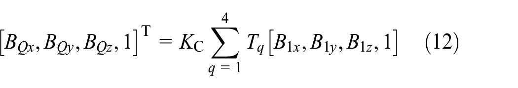

where Tq is the coordinate transformation matrix, q = 1, 2, 3, 4 represents the four planet gears, and θq is the angle at which a single planet gear rotates relative to the absolute coordinate system.
For the worm stator, the surface of the worm is machined with the spiral armature groove as shown in Figure 5. The armature windings embedded in the slot generate a corresponding spatial spiral magnetic field to mesh with the magnetic teeth of the planet gears.

Winding slot trajectory of worm stator armature.
In Figure 5, α is the planet gear mesh position angle and β is the angle between the line, which links the point on the armature slot with the section plane center, and the YOZ plane (revolution position angle of the inner stator). Taking the geometric center of the worm stator as the coordinate origin, the worm axis is the Z-axis and the connection between the worm geometry center and the planet gear center is the Y-axis. The O-XYZ Cartesian coordinate system is established, and the cogging track equation of the worm armature slot can be given as
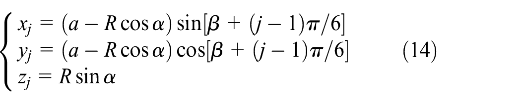
where β = αZ2/2p and j = 1, 2, …, 12. In order to express the spatial helicity of armature winding, the distribution of three-phase current for the 12 armature windings at three different sections at some moment is selected as shown in Figure 6. In the process of calculating the magnetic field generated by the worm current, it is agreed that the direction of the current is represented by the positive or negative of the current value, that is, when the current is positive, the current is perpendicular to the worm end, and vice versa.

Distribution of worm armature current at some moment.
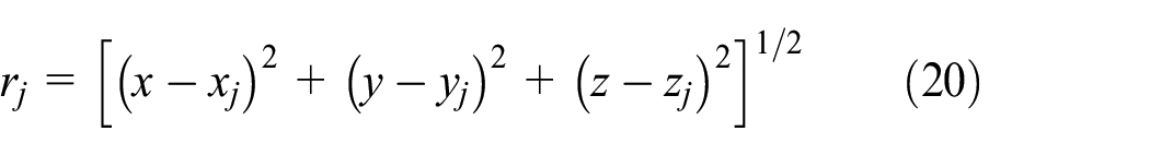
Taking coordinates of any source point on arbitrary slot winding which are (xj, yj, zj), coordinates of any point in space are P(x, y, z), and the vector radius of the field source point to any point in space is r. According to the Biot–Savart law, the mathematical model of stator magnetic field in the worm stator can be established as follows
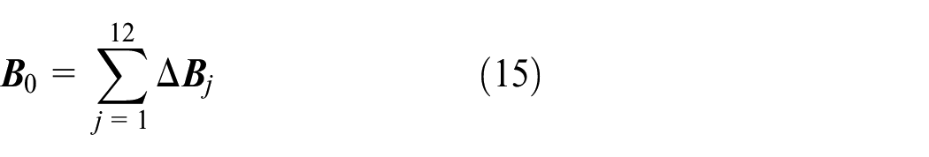
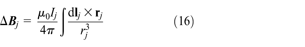
where ΔBj is the flux density generated by a single winding at any point in space P, ΔBj is divided into ΔBjx, ΔBjy, and ΔBjz along the axes of x, y, and z, respectively. The analytical expressions are as follows

where t0 = (β + (j – 1)π/6). The expressions of cross-multiplying radius rj and coefficients A0x, A0y, A0z, and ρ0 of the field source and structural parameters are as follows


The magnetic flux density produced by worm armature at any point in space can be obtained as follows


To sum up, the superimposed magnetic field expression of the inner air gap is as follows
Calculation of the outer air gap magnetic field
The outer air gap magnetic field is generated by two parts of magnets, the outer stator permanent magnet beam and the planet gears’ magnetic teeth. The outer stator is composed of several spatial helical permanent magnet beams, the N and S poles of which are uniformly distributed, located on the outer layer of the planet gears to provide a stable magnetic field. Figure 7 shows the analytical model of the outer stator structure.

Analytical model of the outer stator structure: (a) overall distribution of helical teeth of the outer stator and (b) the equivalent current model of the single spiral tooth of the outer stator.
Taking the field source coordinates of any point on the equivalent current coil A′B′C′D′ as (x0, y0, z0) in Figure 7(b) and combining with Figure 7(a), the trajectory equation of the equivalent current coil of any permanent magnet beam on the outer stator in the O-XYZ coordinate system is established as follows

where x0, y0, and z0 are the coordinates of any source point on the equivalent current coil of the permanent magnet beam, Rk is the radius of the field source point, φ′ is the tooth width angle of the permanent magnet beam, γ is the angle between two adjacent permanent magnet beams, α′ is the face width angle of the stator, β′ is the revolution position angle of the outer stator, and m is the mth permanent magnet beam of the outer stator.
For the single-turn coil A′B′C′D′ for which the current amplitude is


It can be seen from Figure 7 that the trajectory of a single-turn coil is continuous but not smooth and cannot be integrated continuously. It is necessary to divide the equivalent current coil into four sections of smooth current to superposing. The expression of four sections of current derived from the Biot–Savart law is shown in formula (26). Among them, the A′B′ segment and the C′D′ segment differ only by one face width angle of the outer stator


where


The analytical model of the magnetic field in the outer air gap is expressed as follows

Finite element verification analysis
Distribution and analysis of the air gap magnetic field
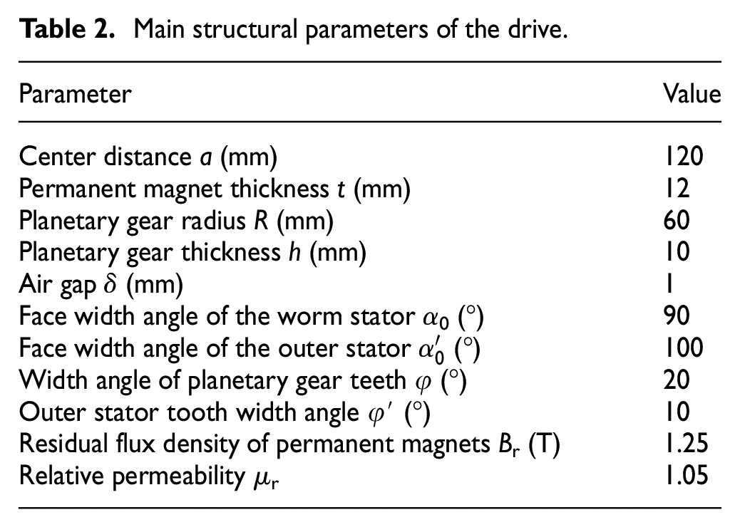
In order to verify the validity of the mathematical model for calculating the spatial air gap magnetic field of the toroidal drive proposed in this article, the air gap magnetic density is simulated and analyzed using the finite element software Ansoft. The main structural parameters of the electromechanical integrated toroidal drive are given in Table 2.
Main structural parameters of the drive.
According to the structural parameters shown in Table 2, the simulation model of the electromechanical integrated toroidal drive is established. The appropriate meshes are set according to the size of each part of the drive. The three-dimensional finite element meshed diagram of the toroidal drive is obtained as shown in Figure 8.
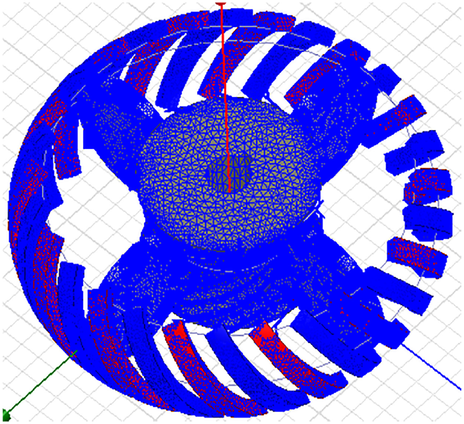
The FE meshed model of the toroidal drive.
The three-phase alternating current with 0.5 A amplitude is applied to the worm winding, and the magnetic flux density distribution of the whole drive can be obtained as shown in Figure 9. From the figure, it can be seen that the magnetic flux density mainly concentrates on the planet gears, armature worm stator, and outer stator. In order to show the distribution of air gap flux density more clearly, the magnetic flux density on the circumferential path with an air gap thickness of 1 mm at α = 0 and α′ = 0 is selected and used as the comparative path with analytical calculation results of the mathematical model. The magnetic flux density distribution of the two air gaps is shown in Figure 10.

The magnetic flux density distribution of the toroidal drive.

Comparison results of the inner and outer air gap magnetic flux densities: (a) inner air gap and (b) outer air gap.
From the comparison results, it can be seen that the inner and outer air gap flux densities calculated by the established numerical analytical model are in good agreement with the finite element simulation results in both waveform and amplitude, which proves that the mathematical model of the air gap magnetic field established by the equivalent current method in this study is effective and feasible.
In order to more intuitively analyze the influence of the main structural parameters on the flux density distribution, the air gap magnetic flux density distributions on the 1-mm circumferential path outside the truncated circle at different position angles are compared. The comparison results are shown in Figures 11 and 12. In addition, the magnetic flux density distributions with different air gap thicknesses at the same position angle are selected for comparison as shown in Figures 13 and 14.
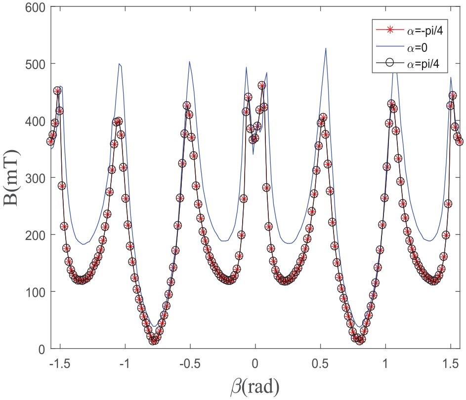
Comparison of inner air gap flux density with different α values.

Comparison of outer air gap flux density with different α′ values.

Comparison of inner air gap flux density with different δ values: (a) α = 0 and (b) α = ±π/4.

Comparison of outer air gap flux density with different δ values: (a) α′ = 0 and (b) α′ = ±π/4.
From the comparison results shown in Figure 11, it can be seen that the flux distribution and magnitude of the inner air gap are identical at α = ±π/4, which shows that the flux distribution of the inner air gap is symmetrical from α = 0 to the two directions of the axial end faces. The flux magnitude at α = 0 is obviously larger than that at the ends. With the change of position angle for the planet gear to the end face, the revolution position angle increases, which leads to an increase in the distance between grooves, thus reducing the overlap of magnetic fields produced by the current of adjacent windings and decreasing the overall magnetic field density of the air gap. Namely, the selection of face width angle of the worm stator affects the magnitude of the magnetic flux density in the inner air gap and that of the induced electromagnetic force and changes the drive efficiency of force and torque.
Because the toroidal drive is an axisymmetric structure, in order to compare the results more clearly, only one quarter of the circumference of the air gap path is shown in Figure 12. It can be seen from the comparison results that the magnetic field of the outer air gap is symmetrically distributed along the Z-axis. In addition, there are double peaks at α′ = 0 but a single peak at α′ = ±π/4. This is because the outer stator beam is a space helical variable cross-section structure. When α′ = ±π/4, only part of the outer stator permanent magnet beam engages with the planetary gear teeth, which results in the loss of one of the peaks. Therefore, in the design of the outer stator, it is important to consider the structural characteristics of the helical variable cross-section varying with the revolution position angle of the outer stator and the treatment of the meshing surface at the end of each outer stator beam.
As shown in Figures 13 and 14, with the decrease in the air gap value, the magnitude of magnetic flux density in both inner and outer air gaps increases, and the increase in the outer air gap is more obvious than that in the inner air gap. When the air gap thickness is reduced from 1 to 0.6 mm, the magnitude of magnetic flux density increases by 30%–45%, but when the air gap value is reduced from 0.6 to 0.2 mm, the magnitude of magnetic flux density increases by only 5%. But the cost of manufacturing and assembly will increase exponentially, so it is necessary to choose the air gap value reasonably for designing the toroidal drive.
Influence of design parameters on torque
Electromagnetic torque is one of the main parameters of the electromechanical integrated toroidal drive. Figure 15 shows the waveform of the torque change in a period of the toroidal drive. The period is given by T = Tm/i, where Tm is the rotational period of the electromagnetic field produced by armature winding and i is the reduction ratio. It can be seen that the overall change trend of the torque is similar to a sine function. However, the planet gear of the drive mechanism participates in electromagnetic engagement only in the range of the face width angle α and α′, and the magnetic teeth outside the range do not produce output torque, which leads to a sudden decay of the torque at the peak of the sine function. It follows that α and α′ are important design parameters affecting the torque of the toroidal drive. The curve of variation of the torque amplitude with α and α′ are shown in Figure 16.

Torque of the electromechanical toroidal drive.
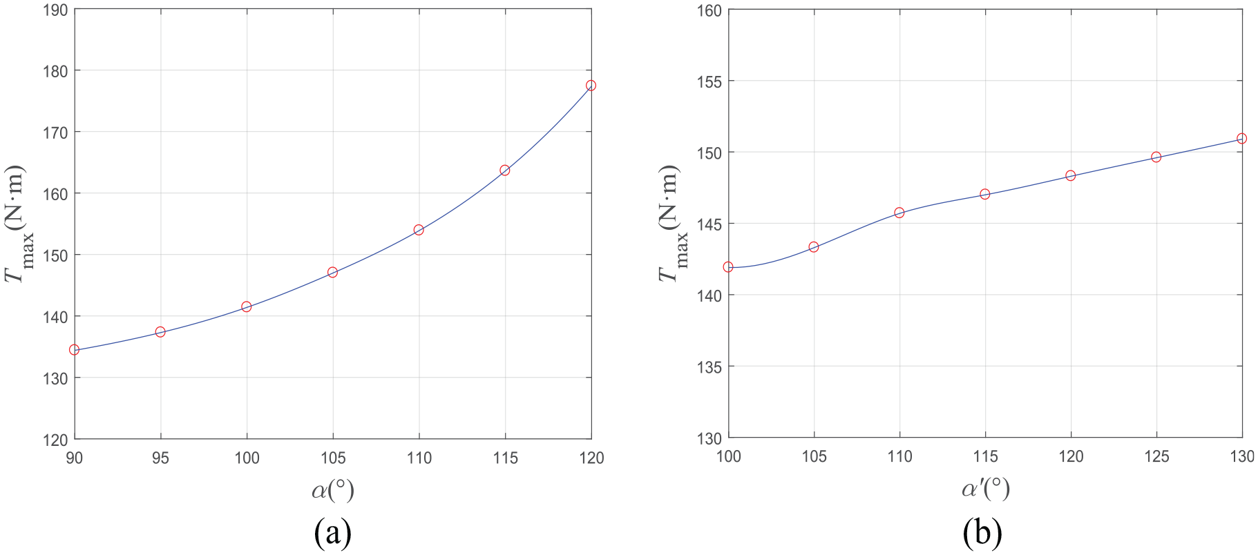
Torque curve with various α and α′ values.
It can be seen from Figure 16 that the increase in both α and α′ can lead to an increase in the torque amplitude, but the difference is that the torque amplitude caused by α increases by about 30%, while that caused by α′ increases only by about 6%. Obviously, the internal air gap is the main working air gap of the drive mechanism. In order to improve the torque of the drive mechanism, the design parameters of the engagement between planet gears and the worm stator should be given priority.
For the electromechanical integrated toroidal drive, the three main components are installed coaxially. In order to ensure the coaxiality between the components in the motion process, the manufacturing and assembly accuracy of the components and the stiffness of the supporting components are ensured as far as possible. Because slight eccentricity will change the air gap thickness between the planet gears and the worm stator and between the planet gears and the outer stator, fluctuation of the torque will increase. When the manufacturing and installation accuracy and brace stiffness meet the technical requirements, it is particularly important to select the air gap thickness during assembly. Figure 17 shows the torque curve for selecting different air gaps.
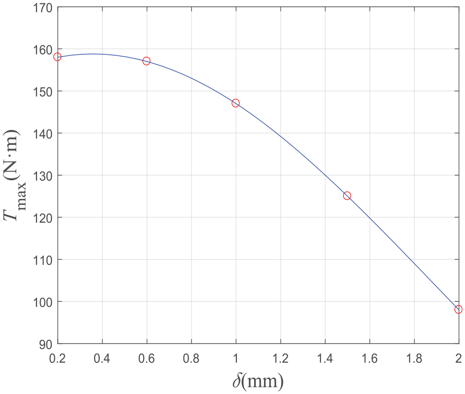
Torque curve with various δ values.
It can be seen from Figure 17 that the torque increases with the decrease in air gap thickness. When the air gap thickness reduces to about 0.5 mm, the torque will change slightly. This is because the magnetic induction intensity of the air gap magnetic field reaches the saturation state. The torque variation caused by the air gap is consistent with the conclusions of the air gap magnetic field mentioned above in Figures 13 and 14. Therefore, when assembling the toroidal drive, the air gap is preferably selected between 0.5 and 1 mm, because the planet gear train will inevitably produce slight eccentric rotation and vibration during operation, which will result in the change of the air gap thickness. When the air gap magnetic field is close to saturation, the change of the air gap thickness will not cause significant fluctuation of the torque, which reduces the vibration and noise of the entire drive system.
Conclusion
In this article, the mathematical model of the double-air-gap magnetic field of the electromechanical integrated toroidal drive is established by the equivalent current method. The introduction of the correction coefficient KC improves the correctness of the mathematical model. The distribution of the inner and outer air gap magnetic fields for the toroidal drive is studied by the mathematical analytic model and finite element simulation. The results show that the magnetic fields of the air gap are symmetrically distributed along the Z-axis and the magnetic flux density magnitude decreases gradually as the revolution position angle increases. The change trend of torque caused by the face width angle of the worm stator, face width angle of the outer stator, and the air gap value is discussed. According to the analysis, the face width angle of the worm stator is more influential to the output torque of the motor than the face width angle of the outer stator. When the air gap value is reduced to about 0.5 mm, the air gap magnetic field is saturated to reduce the torque fluctuation. The results obtained in this article are very important for the optimal design of the toroidal drive system, for reducing the vibration of the system and for improving the system drive capability.
Footnotes
Handling Editor: James Baldwin
Declaration of conflicting interests
The author(s) declared no potential conflicts of interest with respect to the research, authorship, and/or publication of this article.
Funding
The author(s) disclosed receipt of the following financial support for the research, authorship, and/or publication of this article: This project was supported by the National Natural Science Foundation of China (No. 51875408) and the State Foundation for Studying Abroad of China Scholarship Council.