
Abstract
In this work, we propose a robust modeling and analysis technique of the piston-lubrication system considering fluid–structure interaction. The proposed schemes are based on combining the elastohydrodynamic analysis and multi-flexible body dynamics. In particular, multi-flexible body dynamics analysis can offer highly precise numerical results regarding nonlinear deformation of the piston skirt and cylinder bore, which can lead to more accurate results of film thickness for gaps filled with lubricant and of relative velocity of facing surfaces between the piston skirt and the cylinder block. These dynamic analysis results are also used in the elastohydrodynamic analysis to compute the oil film pressure and asperity contact pressure that are used as external forces to evaluate the dynamic motions of the flexible bodies. A series of processes are repeated to accurately predict the lubrication characteristics such as the clearance and oil film pressure. In addition, the Craig–Bampton modal reduction, which is a standard type of component mode synthesis, is employed to accelerate the computational speed. The performance of the proposed modeling schemes implemented in the RecurDyn™ multi-flexible body dynamics environment is demonstrated using a well-established numerical example, and the proposed simulation methods are also verified with the experimental results in a motor cycle engine (gasoline) which has a four cycle, single cylinder, overhead camshaft (OHC), air cooled.
Keywords
Introduction
The reduction of automobile fuel consumption and exhaust gas emission is still important in the field of engine technology due to various environmental regulations. Those technologies are directly related to the reduction of power loss in the internal combustion engine.1,2 The automobile lubrication system is therefore vital because most power loss comes from friction between the piston skirt and the inner surface of the cylinder block, 3 which means that precise predicting of piston movements and appropriate selection of design parameters are prerequisites to design and analysis of the lubrication system.4,5
The main motion of the piston is the reciprocating translation, but the piston also has tilting motion that is mechanically generated by the rotation of the crank shaft. Although the amount of tilting is relatively smaller than the translation, it can lead to a large moment acting on the cylinder block. Therefore, analysis of the tilting has become a key issue in attempts to improve engine performance and reliability. 6
Lubrication analysis therefore allows us to precisely predict the behaviors of the piston skirt and compute the friction loss. In particular, elastohydrodynamic (EHD) lubrication has become popular because it can consider the effect of elastic deformation in computations of the lubrication film thickness. Since the 19th century, many approaches have been taken to tackle EHD lubrication. Zhu and Wang 5 summarized the history of EHD lubrication well. In 1886, based on experimental results, Reynolds 7 published a milestone for theoretical lubrication analysis in a journal bearing. Early studies have been focused on analytical and experimental methods or have focused on simplified numerical approaches due to the lack of computing power.8–11 However, practical EHD lubrication has relied heavily on numerical approaches through model-based simulations. Therefore, because of the advancements of the computer technology, numerical EHD lubrication has been a main issue since the 1980s.12–16 Although EHD lubrication analysis has been dramatically improved over the last 60 years, it has remained an active and attractive research issue. In particular, recent research in EHD lubrication has exhibited a multi-physics point of view, including attempts to solve the fluid–structure interaction (FSI) problem. Since multi-physics based on EHD lubrication directly incurs a heavy computational burden, its numerical efficiency is still a major bottleneck in practical engineering.
In this article, we propose an effective modeling procedure for the piston-lubrication system, a representative FSI problem, coupled with EHD and multi-flexible body dynamics (MFBD) simulation. The piston-lubrication analysis, in which elastic deformations of the piston and the cylinder block as well as overall nonlinear dynamic motion are taken into account, is performed in order to accurately understand the interaction characteristics. Li et al. 17 showed that lubrication behaviors between the piston rings and cylinder liners can indeed be affected by the dynamic deformations of cylinder structures through their research. Piston-lubrication analysis is based on EHD theory4,5 which is used to represent the thickness and pressure of the fluid film generated by the relative motions of the objects, which exhibit elastic deformation, and the hydrodynamic pressure, which is computed using the Reynolds equation. 7 Greenwood and Tripp’s 18 asperity contact model is additionally used to cover the direct metal-to-metal contact in dry condition considering the roughness effect. In particular, unlike the typical rigid body approaches, MFBD simulation is used to precisely compute the nonlinear dynamic motions and the local elastic deformations of the piston skirt and the cylinder block. The flexible bodies of the piston and cylinder contain too much degree of freedom. Since the transient coupling analysis of MFBD and EHD requires excessive computation for structural analysis, so the modal reduction technique for the flexible bodies is applied for the appropriate computation and this method is deemed appropriate because the deformation of piston and cylinder due to oil pressure is not large. In a similar study, Kumar et al. 19 analyzed transient EHD using the modal reduction technique for the engine bearing and obtained stable results according to the appropriate mode selection. JH Schmidt 20 suggested efficient numerical solution procedure for the lubricated impact problem which captures structural dynamic effects of complex geometries using modal reduction technique. Component mode synthesis (CMS), which is a representative modal reduction technique, is used to accelerate the simulation speed in this research.21–28 We then employ the Craig–Bampton (CB) formulation, which is a standard CMS method. 21 The proposed modeling scheme of the piston-lubrication system is fundamentally an FSI problem; as such, it can be effectively tackled by an iterative co-simulation of the EHD and MFBD models, which together make a weakly coupled approach.
In the sections, “Summary of MFBD with modal reduction” and “CB-like formulation,” we first summarize the MFBD formulation with the modal reduction method. The EHD model is introduced in section “EHD lubrication.” The overall process for the numerical method proposed in this article is described in section “Numerical process.” Numerical testing using the proposed coupled modeling process of a simple piston-lubrication system is presented in section “Numerical studies.” In section “Experimental validations,” the proposed simulation scheme is also validated with the experimental results. The conclusions are given in section “Conclusion.”
Summary of MFBD with modal reduction
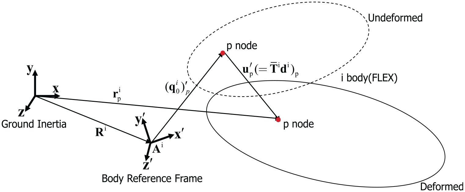
In this section, we summarize the MFBD formulation using the well-known floating reference frame.29,30 We also present the coordinate reduction of the flexible body. The equations of motion of the multi-flexible body model on body i are

where
The generalized coordinate vector

where
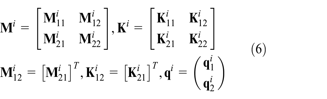
Using the transformation matrix

and the component matrices and vector are computed as

In addition,
Various projection techniques for coordinate reduction have been proposed since the 1960s; they can be categorized according to which mathematical basis is employed. Among the various techniques, eigen solutions, constraint modes, the Krylov subspace scheme, and singular value decomposition (SVD) are the mainly used basis vectors.33–41 Since these basis vectors have their own advantages and disadvantages, users have to thoughtfully select an optimal basis vector, or have to combine them to accurately approximate the flexible model.
Finally, the global position vector
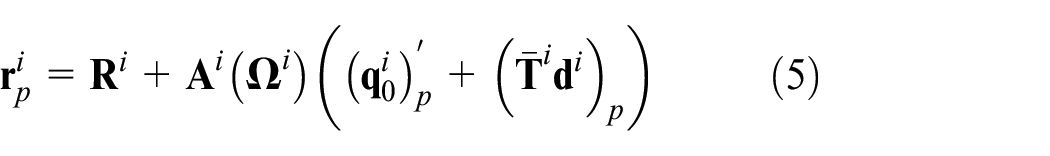
where
Nodal position of the flexible body.
The combustion engine consists of four main parts: connecting rod, crank shaft, piston, and cylinder blocks. In particular, the piston and cylinder block are the main components in the typical piston-lubrication system; they should be modeled as flexible bodies for EHD lubrication: Figure 2 shows a schematic diagram of the piston and the cylinder block in the piston-lubrication system. The each reference frame of the piston and the cylinder block are denoted using the subscripts p and c at a certain time t.

Schematic of the piston and cylinder block structure with reference frame.
The arbitrary position vector of flexible piston and cylinder
CB-like formulation
The CMS method, combining the eigen solutions and constraint modes, is popular and widely used for coordinate reduction of a linear elastic body in the multibody dynamics (MBD) field. In particular, the CB-like formulation, 21 which is a standard CMS method, is employed in this work. In the CB method, each body is connected by the joints and there are some parts which force is applied to. The degrees-of-freedom (DOFs) associated with these parts is set as the interface and are called the interface DOF. The other DOFs in the configuration of the flexible body are defined as the internal DOFs. With an assumption of free vibration, we then rewrite the component matrices and vectors in equation (1) as
Transformation matrix
where

in which

where
EHD lubrication
EHD lubrication is a mode of fluid-film lubrication in which hydrodynamic behavior is significantly increased by surface elastic deformation; the viscosity is also increased due to high pressure. The dynamic behavior of a lubricant film between a piston and a cylinder block is described by a Reynolds equation.4,5 In addition, Greenwood and Tripp’s asperity model, which is a well-known contact theory that considers the roughness effect, is used to compute the contact pressure and force in dry condition. 18
Reynolds equation for flexible piston-lubrication system
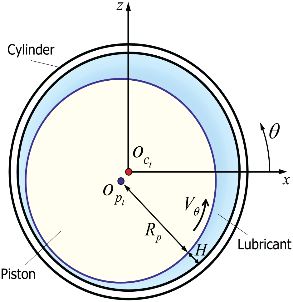
In order to perform EHD lubrication, the lubrication area and the coordinate system for lubricant behavior should be defined first because the governing equation for the lubricant is then formulated based on this coordinate system. The coordinate system is located at the center position of the cylinder in its initial state and its y-axis, which is cross product of z- and x-axis in Figure 3, is set parallel to the axial direction of the cylinder. It is a fixed coordinate system for defining variables for the lubrication analysis. Figure 3 shows an arbitrary cross section of the piston-lubrication model. h is the lubrication film thickness which represents clearance between cylinder and piston in radial direction on the

where

in which

where

where x denotes the circumferential direction coordinate and y denotes the axial direction coordinate. Considering the finite volume discretization in equation (13), the film thickness and the velocity vectors can be defined by the nodal position vector

Cross-section of the piston-lubrication model.
Then, the following numerical system of equations for the pressure
Asperity contact model
When the film thickness is very thin, direct metal-to-metal contact can occur, which means that massive pressure might be added to the hydrodynamic pressure computed by the Reynolds equation. In particular, we here use the well-known Greenwood and Tripp 18 asperity contact model to consider the surface roughness in the piston skirt and inner surface of the cylinder block. The asperity contact pressure can be calculated as follows

where

The calculated total pressure p is calculated as the nodal force by multiplying the characteristic area for each node of the flexible body. This nodal force acts in the centripetal direction of the coordinate system for lubrication analysis and applies to
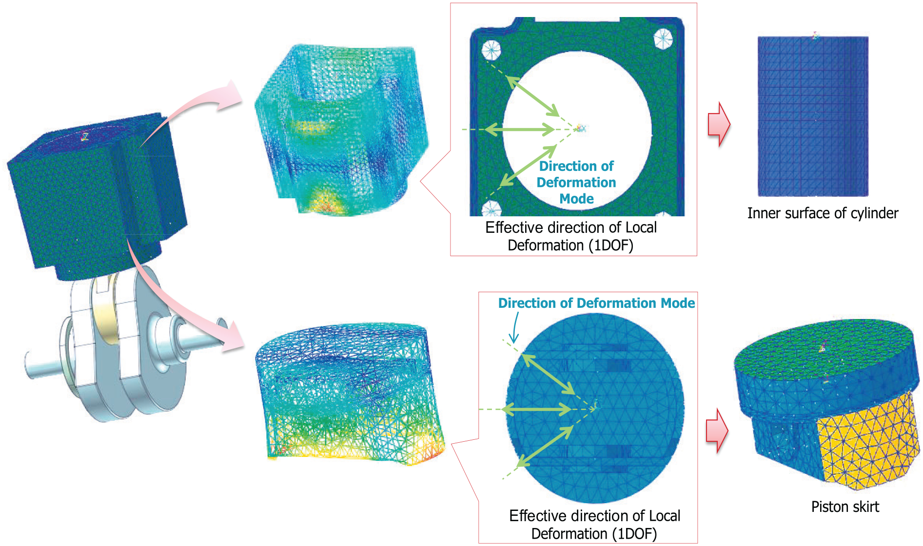
Modal force by gas combustion pressure
In the piston-lubrication system, pressure resulting from gas combustion should be considered to check the characteristic of piston-lubrication system because it is a main factor to drive system. In order to apply gas force to modal reduced flexible body, first we have to compute nodal force resulting from the gas pressure. The nodal force
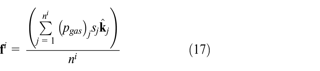
where
Numerical process
In this work, we focus on developing a co-simulation procedure of EHD and MFBD solvers, which is highly effective from a computational point of view, and which is a kind of weakly coupled simulation. The numerical process is specifically described in Figure 4.

Numerical process of piston-lubrication model.
First, transformation matrix
Numerical studies
The proposed coupled modeling process of the piston-lubrication system is implemented in the RecurDyn™ MFBD environment.
46
We here consider a piston-lubrication example to evaluate the performance of the proposed numerical process (see Figure 5). In the example model, the rod and crank shaft are connected by revolute joint and they are modeled as rigid bodies. Driving force of piston-lubrication system is derived from rotation of crank shaft. And, the rod and piston are connected by revolute joint in point A at which master node are connected to the slave nodes on flexible piston. The piston and cylinder block, which are related to the lubrication region, are modeled as flexible bodies. Parabolic tetrahedral solid elements are used for the piston and the cylinder block. The axial length of inner space of cylinder block is 95 mm and 40 by 40 fluid mesh grids are distributed in the lubrication area between the piston skirt and the inner surface of the cylinder block. In order to calculate the Reynolds equation for the lubrication area, first define the coordinate system for the Reynolds equation as shown in Figure 5. Here, the circumferential direction is defined as the direction of rotation from the z-axis to the x-axis, the axial direction is the y-axis, and the radial direction for defining the film thickness is defined on the

Numerical example of piston-lubrication system.
Examples of selected mode shapes.
Asperity contact parameters.

For the numerical study, we consider a crank rotation as
For the two numerical cases, we plot the lateral motion and the rocking angle of point A (see Figure 5), which is the center point of the piston connected with the rigid body elements (RBEs). Here, lateral motion indicates movement of point A in x direction and rocking angle which is the piston’s secondary motion indicates the rotation of point A in z direction which is cross product of x- and y-axis. They can be seen in Figures 7 and 8. Numerical results show that the lateral motions and rocking angle of the piston, considering the MFBD simulation, might be different from the results obtained using MBD, although all results show the same tendency. This implies that the elastic behaviors of the piston and the cylinder block can lead to significant effects in the EHD lubrication model. It also implies that a great enough number of modes that can represent the elastic behaviors of the flexible body well might be useful in the modal reduction model.

Lateral motion of point A.

Rocking angle of point A.
We also investigate the pressure and thickness distribution according to the circumferential angle. Those results clearly show different phenomenon in the MBD and MFBD approaches. We found that high pressure occurs when the simulation time is 0.018 s, as can be seen in Figure 9. It is also seen that the contours of the MBD and MFBD approaches can be clearly distinguished from each other. As shown in Figure 10, in the MBD case, except for the elastic modal effect, the maximum pressure occurs at the center of the piston skirt; however, in the MFBD case, the maximum pressure occurs at the circumferential end of the piston skirt. This phenomenon can be understood through the thickness curve plotted in Figure 11. It can be seen that in the case of the MFBD results, the piston and the cylinder block can represent elastic deformation in which the piston skirt becomes bent inward. Thus, the oil film thickness increases around the center of the piston skirt. This causes the hydrodynamic pressure to decrease around it. Meanwhile, there is no increase of film thickness in the case in which only the rigid body motion is considered; then, the distribution of the hydrodynamic pressure is different from that in the MFBD results.

Pressure contours of the MBD and MFBD approaches in case 1: MBD (left) and MFBD (right).

Pressures according to angle on the left-hand side of the piston skirt.

Film thicknesses according to angle on the left-hand side of the piston skirt.
Figures 12 and 13 show minimum thickness and friction force in axial direction for the rigid case and a case with 60 modes during the operation time. In the case of friction force, the shear stress in the Newtonian fluid due to the viscosity and the friction force due to the asperity contact are combined. In the upstroke situation, the friction force is smaller when the flexible body (a case with 60 modes) is shown, which may be related to the larger minimum thickness of the flexible body under similar circumstances.
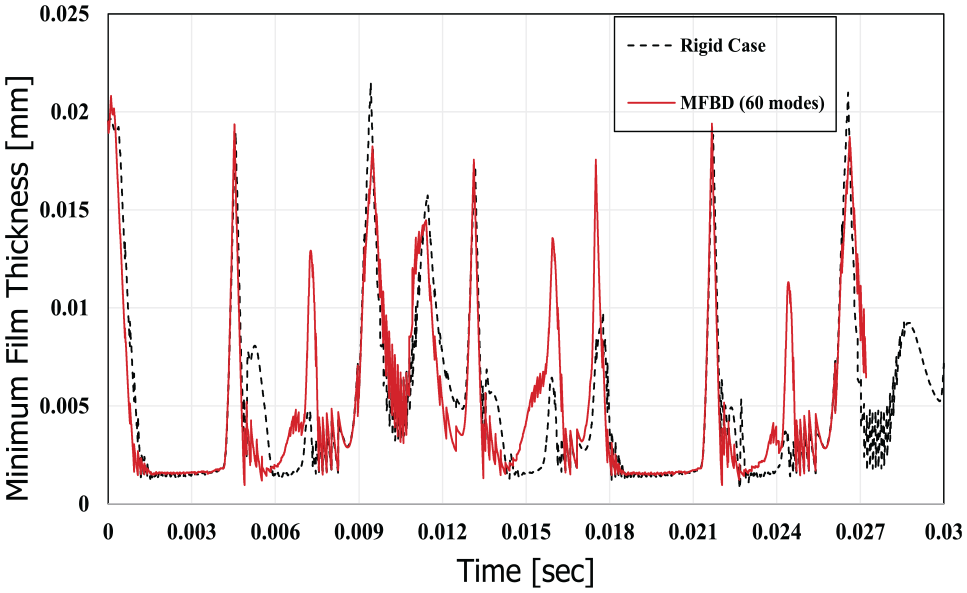
Minimum thickness.

Friction force.
We here examine the computational costs of increasing the number of modes in the MFBD analysis. The results are summarized in Table 2. To theoretically compute the operation counts, we here consider two major computational processes: number of Jacobian evaluations and number of residuals. It can be seen that the computational cost dramatically increases as the number of modes increases. The reason for this is that the operation of Jacobian evaluations, which are derivatives of the pressure force by the system coordinates to meet the force equilibrium in an implicit integrator, increases dramatically. It should also be noted that the present piston-lubrication model is quite simple; it is modeled for the feasibility study only. This means that the practical model might be much more complicated and have around a million DOFs; this allows us to conclude that if the interpretation is made through a full nodal analysis rather than through the modal model reduction approach, its computational burden will not be acceptable in engineering practice.
Comparison of computational costs: number of Jacobian evaluations (NJAC) and number of residual evaluations (NRES).

Experimental validations
We here consider another piston-lubrication example (see Figure 14) to check how valid the numerical results are. This example model is compared with the experimental results by Honda Motors for motor cycle engine (gasoline) which has four cycles, single cylinder, overhead camshaft (OHC), air cooled to verify the numerical results. The measurement results such as lateral motion and rocking angle are compared to the numerical analysis results. In the example model, the rod and crank shaft are connected by revolute joint and they are modeled as rigid bodies. Driving force of piston-lubrication system is derived from rotation of crank shaft. The rod and piston are then connected by revolute joint in point A at which master nodes (see Figure 14) are connected to the slave nodes on flexible piston. The piston and cylinder block, which are related to the lubrication region which is formed between piston skirt and inner surface of cylinder block, are modeled as flexible bodies. Parabolic tetrahedral solid elements are used for the piston and the cylinder block. The axial length of inner space of cylinder block is 103.55 mm and 40 by 40 fluid mesh grids are distributed in the lubrication area between the piston skirt and the inner surface of the cylinder block. As in the previous test case, we define a coordinate system for calculating the Reynolds equation and obtained the boundary conditions accordingly. In order to obtain this, the position and velocity information of the nodes of the piston skirt and the cylinder inner surface nodes were interpolated. The numerical parameters for EHD of the example model are presented in Table 3. As in the test case of section “Numerical studies,” in order to consider the effect of deformation on the lubrication film, the mode shapes are selected so that deformation in the direction that affects the film thickness is mainly set (Figure 15).

Validation model of piston-lubrication system.
Asperity contact parameters.


Selected mode shape for validation model.
For the numerical study, we consider a crank rotation as
In order to reflect the effect of combustion pressure on the piston top, measurement combustion pressure according to crank rotation is applied to the piston top, see Figure 16. Combustion pressure is maximized when crank angle reached to 10° and this type of combustion pressure is repeatedly applied to the piston during the entire simulation. This combustion pressure is employed to define nodal force for reduced flexible body (see equation (17)), and the resulting nodal force is also employed to define

Application of combustion pressure to piston top.
For the validation test with experimental result, we plot the lateral motion and the rocking angle of point A (see Figure 14), which is the center point of the piston connected to the RBEs. Here, the definition of lateral motion and rocking angle is the same as in the test case in section “Numerical studies.” They can be seen in Figures 17 and 18. Numerical results expressed according to crank rotation during two cycles show similar tendency to the experimental results. In particular, it shows similarities in overall amplitude variation.
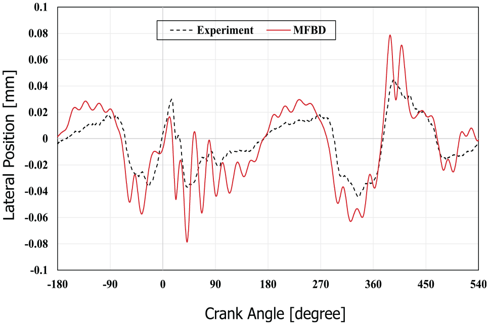
Lateral motion at point A according to rotation of crank shaft for the validation test model (third and fourth stroke cycle).

Rocking angle at point A according to rotation of crank shaft for the validation test model (third and fourth stroke cycle).
Conclusion
In this study, we proposed an efficient coupling method for the EHD and MFBD analyses for a piston-lubrication system. In order to convince ourselves of the computational efficiency, the modal reduction model with standard CB formulation is employed. In order to analyze the lubrication characteristics of the piston skirt and the cylinder inner surface, the lubrication area is set to the interface node, and the mode shape that influences the lubrication analysis is selected. In the lubrication analysis, to cover metal-to-metal contact in dry condition, we also consider the asperity contact model. In the proposed modeling procedures, EHD and MFBD simulations are repeated by updating the elastic deformation and the hydrodynamic pressures. By developing the efficient coupling method between MFBD and EHD, the users can analyze the system which includes piston-lubrication problem in multibody system. The numerical results show that the elastic behaviors of the flexible bodies can play significant role in the computation of the film thickness, which implies that EHD lubrication with MFBD simulation might be considered to precisely predict piston-lubrication behaviors. The numerical results also demonstrate that coordinate reduction in the MFBD simulation is necessary to effectively handle this problem in engineering practice, and the proposed numerical method is verified to some extent through comparing to experimental results.
Footnotes
Handling Editor: James Baldwin
Declaration of conflicting interests
The author(s) declared no potential conflicts of interest with respect to the research, authorship, and/or publication of this article.
Funding
The author(s) disclosed receipt of the following financial support for the research, authorship, and/or publication of this article: This research is supported by 2018–2019 KyungHee University Research Support Program.