
Abstract
Capsule-type plate heat exchanger has the advantages of less deposition and low flow resistance. Based on previous research, numerical studies of capsule-type plate heat exchangers with different capsule lengths and widths for the Reynolds number ranging from 600 to 10,000 are performed. The results show that wake vortices, transverse vortices, and longitudinal vortices generate in the channels by the flow shearing and separation. The vortices promote the swirl and flow destabilization, exchange the fluid between the boundary layer and the mainstream, and thus enhance the heat transfer in the capsule-type plate channels. Wake vortices transform to longitudinal vortices with increasing Re. The number of the longitudinal vortices decreases and the size of the longitudinal vortices increases with increasing Re or the decreasing length−width ratio of the capsule. In addition, Nusselt number and friction factor decrease with the increasing length−width ratio of the capsule.
Introduction
Plate heat exchangers are widely used in industrial applications such as food processing, petroleum refining, chemical engineering, and refrigeration owing to their compactness, flexibility, and ease of cleaning. 1 To reduce energy cost, developing high-efficiency and low energy consuming plate heat exchangers becomes a critical issue.
Heat transfer and flow performance of heat exchangers can be improved by geometry optimization. For single-phase flow in chevron-type plate heat exchangers, extensive studies have been done through experiments and numerical simulations. 2 Nusselt number and friction factor are found to increase with chevron angle.3,4 Wang et al. 5 concluded that a smaller corrugated pitch could increase the heat transfer and flow resistance by increasing the contacts points of the plates. Gulenoglu et al. 6 observed strong influence of geometrical properties such as enlargement factor, channel flow area, and port diameter on the thermal and hydraulic performance of a heat exchanger from their experimental results.
While less attention is given to other type plate heat exchangers. Durmus et al. 7 experimentally investigated three plate heat exchangers under the condition of parallel and counter flows. The experimental results showed that both heat transfer and pressure drop of an asterisk plate heat exchanger are higher than flat plate heat exchanger and less than corrugated plate heat exchanger. Luan et al. 8 proposed a new corrugated plate heat exchanger with plates consisting of longitudinal and transverse corrugations. Compared with a traditional chevron-type plate heat exchanger, the resistance to flow of the new plate heat exchanger decreased by more than 50% and heat transfer decreased by 25%. Piper and colleagues9–11 investigated the influence of the pillow-plate geometry on thermo-hydraulic performance and derived new design equations for predicting the flow and heat transfer performances of pillow-plate heat exchangers. Li et al. 12 experimentally studied the flow and heat transfer of discrete rib plate heat exchangers, where the inclined discrete ribs are similar to capsules. The front vortex, the rear vortex, and the main vortex are observed in discrete rib channels. The heat transfer enhanced by 5%–15% and the flow resistance decreased by more than 30% compared with inclined continuous rib channels.
Zhang and colleagues13,14 numerically investigated the heat transfer enhancement in capsule-type plate heat exchangers (CPHEs). Vortices generated in the plate channels are found to be the main mechanism of heat transfer enhancement, and a good performance is concluded with respect to Nu/f1/3. However, the capsule geometries optimization still needs to be investigated. Moreover, insufficient performance correlations seriously restrict industrial applications.
To optimize the geometry of CPHEs, and to better understand the vortex pattern, the impact of the capsule length and width is numerically studied in this work. The correlations of friction factor and Nusselt number (Nu) are derived as functions of Reynolds number (Re) and length–width ratio of the capsule, and two different performance evaluations are conducted to assess the comprehensive performance of the CPHEs.
Physical and numerical models
Geometrical parameters
As shown in Figure 1(a), CPHEs compose of plates with approximate ellipsoidal embossing similar to a half capsule. Among the plates, a cross-current flow is organized. It is noteworthy that the concave and convex capsules have the same shape and are distinguished by the relative position of the fluid. For the fluid indicated by the blue arrows in Figure 1(a), the concave and convex capsules are pointed out, respectively. The concave capsules and the convex capsules are perpendicular, and the mainstream direction parallels the array direction of the concave capsules, which is the most appropriate structure proposed by Zhang et al. 14 The main parameters of the capsules are length (l), width (d), and height (h). Other parameters depend on the length and width, such as the angle between concave capsule and the mainstream direction (θ), and the length of the unit cell (lc), as shown in Figure 1(b). In this work, CPHEs with different capsule lengths and widths are investigated. Small capsule height leads to a small hydraulic diameter and results in high compactness. The height of capsules is set to 2.5 mm, which is commonly encountered in various industrial applications. Figure 2 and Table 1 show the specifications of the capsules. CPHEs A, B, and C have the same width (10 mm) and different lengths (20, 15, and 25 mm, respectively), while CPHEs A, D, and E have the same length (20 mm) and different widths (10, 5, and 15 mm, respectively).

Schematics of (a) a capsule-type plate and (b) the smallest unit cell.

Front view of capsule-type plates.
Specifications of the capsules.

CPHE: capsule-type plate heat exchanger.
Calculation domain and boundary conditions
For each CPHE, the smallest unit cell is adopted as the computational domain to minimize the computational cost. As shown in Figure 1(b), the unit cell represents the characteristics of the main heat transfer area of a CPHE. The front and back surfaces are set as wall with constant temperature (333 K) and no-slip velocity conditions. Periodic boundary conditions are employed for the surfaces in the spanwise (y-axis) directions. When the fluid flows from the inlet to the outlet (x-axis), a period is complete. The flow parameters such as velocity and kinetic turbulent energy of the inlet boundaries are set by the outlet profile of the previous period, and the temperature is set as 293 K. When the pressure loss and the heat transfer coefficient of the last few periods are almost constant respectively, it is considered that the flow and heat transfer in the channel are fully developed, and the data would be analyzed.
Numerical method and data reduction
Incompressible water with constant physical properties is selected as the working fluid. Artificial materials are also used to investigate the influence of Prandtl number. The gravity effect is neglected as well. In this study, we investigate turbulent flow in CPHEs based on Reynolds number ranging from 600 to 10,000. ANSYS CFX 16.0 and shear stress transport (SST) k-ω turbulence model are employed. SST k-ω model combines the advantages of k-ε and k-ω models. When SST k-ω model is used, k-ω model is activated to achieve an accurate description of flow separation in the negative pressure region and the turbulence shear stress transmission in the near-wall region. While in the mainstream area, k-ε model is activated to avoid over forecasting eddy viscosity of the turbulent flow. SST k-ω model is considered as an appropriate turbulent model for simulating the flow inside a corrugated conduit. 15 Second-order upwind scheme is selected for calculation, with the convergence criteria of the root mean square residuals of 10−5. Detailed introduction of the numerical method can be found in the works of Zhang et al. 13
In this work, hydraulic diameter De is defined as follows

where A0 is the minimum free-flow area, lc is the flow length, and S is heat transfer area. Compared with conventional hydraulic diameter 4A0/P, where P is the wetted perimeter, De concerning the average wetted perimeter of the whole channel is more applicable for the flow passages with expanding/contracting sections 16 and has been successfully used. 17 Re is defined as follows

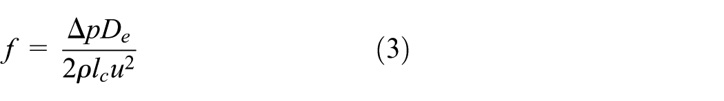
where u and ν represent the inlet velocity and kinematic viscosity of fluid, respectively. Fanning friction factor (f) is selected to characterize the flow and is defined as follows
where ρ is the fluid density. Local heat transfer coefficient hl, heat transfer rate Q, average heat transfer coefficient have, and Nu are defined as follows


where q is local heat flux, Tw and Tf, l are the temperatures of wall and the local fluid, respectively, m and cp are fluid mass flow rate and specific heat capacity, respectively, Tf, ave is the average temperature of the fluid, and λ is the thermal conductivity of the fluid.
Mesh and model validation
The meshes of all domains are unstructured tetrahedral elements and are generated using ICEM CFD, version 16.0. To improve the accuracy of the simulation results, the vicinity of wall is refined with triangular prism meshes as shown in Figure 3. Mesh independence is examined to ensure the reliability of the simulation results. For the cell of CPHE A, as shown in Figure 4, the differences of f and Nu between the results of 1,497,665-mesh system and 5,240,746-mesh system are less than 2% and 3%, respectively. Therefore, the 1,497,665-mesh system is validated and employed in this research. Similar validations are also carried out for every other CPHEs.

Meshes with tetrahedron and triangular prism near the wall.

Mesh independence validation.
Owing to the lack of heat transfer experimental results of CPHEs, the simulation results of a chevron-type plate heat exchanger obtained by the aforementioned model is compared with the experimental correlations reported by Khan and colleagues18,19 The corrugation depth, pitch, and angle are 3.6 mm, 13.25 mm, and 30°, respectively. As shown in Figure 5, the maximum discrepancy between the predicted correlations and the numerical results of friction factor and Nu are less than 9% and 13%, respectively. The good agreement indicates that the present numerical method is reliable to investigate turbulent flow and heat transfer in corrugated channels.

Model validation.
Results and discussion
Flow and heat transfer in a capsule-type plate channel
Vortex pattern
To clarify the mechanism of the heat transfer enhancement in capsule-type plate channels, CPHE A is selected as a standard case to discuss. Vortices are the main mechanism of the heat transfer enhancement in capsule-type plate channels. To investigate the vortex pattern, two-dimensional (2D) and three-dimensional (3D) streamlines are plotted in Figure 6. When Re is low, wake vortices and transverse vortices (TVs) generate in the channels, as shown in Figure 6(a). The wake vortices are formed by flow separation similar to the classical Karman vortex street. The axis of the wake vortices is perpendicular to the plates, and thus the vortices hardly promote the mass exchange between the boundary layer and the mainstream or enhance the heat transfer. TVs generate in the convex capsules by the shearing action between the mainstream and the fluid in the convex capsules, whose axis is approximately parallel to the convex capsules. The structure of TVs is simple and stable and does not change with Re. However, when Reynolds number is increasing, the wake vortices become unstable. High momentum fluid separates along the edge of the capsules and rolls up to longitudinal vortices (LVs). 20 The structure of the vortex system is strongly influenced by the channel geometry and Reynolds number. As shown in Figure 6(b), two LVs generate at the downstream of the concave capsules. When Re is high, the region of swirl becomes larger due to the high flow velocity, and a large LV forms in the downstream of the concave capsules as shown in Figure 6(c).

2D and 3D streamlines of (a) CPHE A, Re = 825, (b) CPHE A, Re = 4282, and (c) CPHE A, Re = 10,370.
Turbulent kinetic energy
To complete the analysis of the flow characteristics, the distribution of turbulent kinetic energy (TKE) is investigated. TKE, kinetic energy per unit mass in the fluctuating velocity field, 21 represents the energy associated with vortices. 22 As shown in Figure 7, TKE non-uniformly distributes in the channel. The minimum zones appear at the leeside of the concave capsules due to the small velocity of the fluid. TKE is higher at the windward side of the concave capsules and reaches its maximum at the downstream of the concave capsules as shown in the center section (z = 2.5 mm), where the LVs generate and promote the flow destabilization.

TKE distributions of z-axis sections of CPHE A.
Temperature
The temperature distributions of CPHE A are shown in Figure 8. Most of the fluid is much cooler than the plate (333 K), so the fluid between 293 and 303 K is thoroughly distinguished, and the fluid hotter than 303 K is marked by red. As shown in Figure 8, the temperature of the mainstream remains constant as 293 K, while the fluid near the concave capsules has higher temperature. The wake region behind the concave capsules with low temperature gradients is small and almost has the same finger shape as the low-velocity region as shown by Zhang et al. 13 The reason behind this is that the LVs bring in high-momentum fluid and shrink the wake region. Moreover, the LVs lead to a spiraling motion and exchange the fluid between the boundary layer and the mainstream, 23 integrated with the fluid impingement at the windward side of the concave capsules, enhancing the heat transfer. Consequently, the fluid near the concave capsules is hotter than the mainstream, where the local convective heat transfer coefficient is high. 13
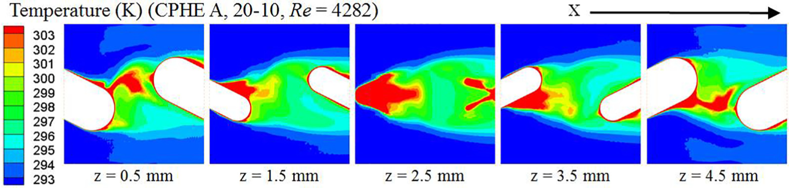
Temperature distributions of z-axis sections of CPHE A.
Local heat transfer coefficient
Figure 9 shows the distribution of local heat transfer coefficient hl with Re = 4282 of CPHE A. hl is large at the windward sides of the capsules, that is, the upstream part of the concave capsules and the downstream part of the convex capsules, where the vortices generates and fluid impinges on the wall. Besides, hl at the tail of the concave capsules is low owing to the flow stagnation and separation of the wake region.

Distribution of local heat transfer coefficient hl of CPHE A.
Influence of capsule length and width on flow characteristics
Vortex pattern
In addition to Reynolds number, the vortex patterns are also affected by the capsule length and width. When Re is low, the vortex patterns show similar characteristics in these five capsule-type plate channels. Two wake vortices and two TVs generate at the downstream of the concave capsules and in the convex capsules, respectively. However, when Re increases, for example about 3900, different vortices are observed, as shown in Figure 10. In Figure 10, CPHEs B and E have a large LV at the downstream of the concave capsules, while CPHE C has three smaller LVs and CPHE D has no LVs at the corresponding position. Comparing the LVs at the downstream of the concave capsules, we can find that the number of those LVs increases and the size of LVs decreases with the increasing length−width ratio of the capsule. The reason is that the angle (θ) between the concave capsule and the mainstream direction (y-axis direction) decreases with the length−width ratio. Large θ indicates the strong flow turbulence caused by the capsules. Moreover, the concave capsules on the two plates are arranged in opposite y-axis directions. Thus the larger the θ, the bigger the velocity difference in y-axis direction between the upper (z > 2.5 mm) and lower (z < 2.5 mm) fluid. Consequently, the fluid rotates intensely. The two factors result in the giant vortex behind the concave capsules for the CPHEs with small length−width ratio. Vice versa, for CPHEs A and C, the small θ caused by large length−width ratio and the relatively narrower capsules result in the small vortices behind the concave capsules. Note that, the 3D streamlines of CPHE D (l = 20, d = 5) are much smoother than the others. In CPHE D, LVs generate only at the sides of the concave capsules because the capsule width of CPHE D is the smallest and the length−width ratio is the largest. Finally, when Re keeps increasing, a large LV generates at the downstream of the concave capsules for each CPHEs except CPHE D. In summary, the number of the LVs increases and the size of the LVs decrease with the increasing length−width ratio of the capsule.

2D and 3D streamlines with Re about 3900: (a) CPHE B, Re = 3975, (b) CPHE C, Re = 3906, (c) CPHE D, Re = 3637, and (d) CPHE E, Re = 3783.
TKE
The TKE distributions of the CPHEs are similar, thus the value of TKE is discussed to show the influence of the capsule length and width on the flow. Table 2 shows that the volume average TKE decreases based on the length−width ratio of the capsule, except CPHE E (l = 20, d = 15). Besides the influence of θ discussed in section “Vortex pattern,” another reason is that the area coverage ratio of the capsules in the channel decreases with l/d. When the capsule length is fixed, there is no doubt that narrower capsules have smaller area. Moreover, when the capsule width remains unchanged, although the area of the single capsule increases with capsule length, the area of the flat regions increases more rapidly and the area coverage ratio of the capsules decreases. Smaller length−width ratio leads to larger area coverage ratio of capsules and larger θ, resulting in stronger turbulence and bigger TKE in the channels. Notice that, the unexpected small TKE of CPHE E might be attributed to the small wall curvature of the plates due to the widest capsules. When the width–height ratio of the capsule is too large, the capsule plates become flat, thus the turbulence is not strong.
Volume average turbulent kinetic energy of CPHEs.

CPHE: capsule-type plate heat exchanger; TKE: turbulent kinetic energy.
Performance and evaluation
To investigate the performance of CPHEs, the variations of Nu/Pr1/3 and f with Reynolds number are plotted in Figure 11, in which the dots with different colors represent numerical results of different heat exchangers. The data of CPHEs A, B, C, and D show the decrease of Nu and f with the length−width ratio of the capsule, and Nu and f of CPHE E are smaller than other CPHEs. The reason is due to the large width–height ratio of the capsule as we mentioned before.
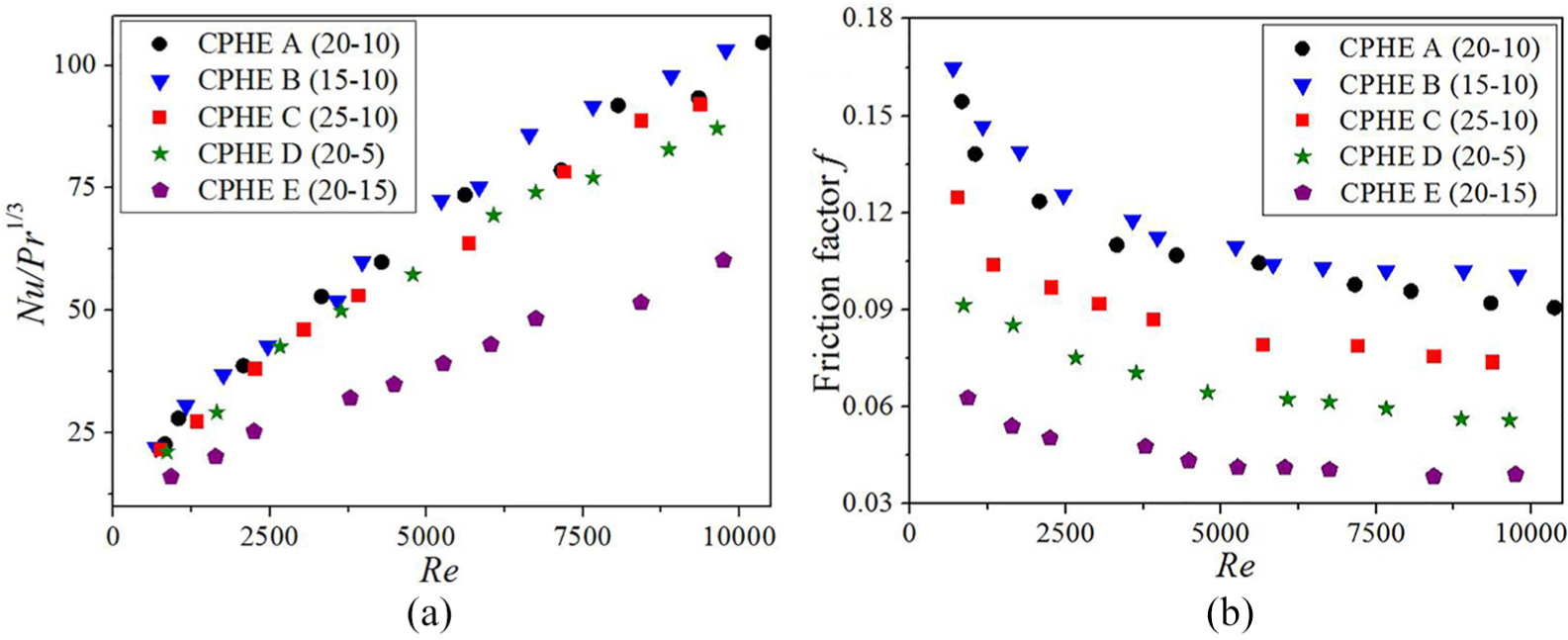
Variations of (a) Nu and (b) f with Re of CPHEs.
Nu and f correlations are derived from the simulation results to predict the heat transfer and pressure drop of CPHEs. Performance of CPHE E is obviously different from the other CPHEs, thus the data of CPHE E is not used for the correlation derivation. Performance of CPHEs with capsules wider than 10 mm is an issue that still needs to be investigated. The following correlations are drawn


The aforementioned correlations are valid for Reynolds number from 600 to 10,000 and Prandtl number from 1 to 10 for CPHEs with h of 2.5 mm, l/d from 1.5 to 4, and d no more than 10 mm. The correlations agree well with the simulation results. The maximum deviations between correlation and simulation data are 9.7% of Nu and 13.5 % of f. About 95% of data lie within ±10% compared to the simulation results as shown in Figure 12.

Accuracy of the prediction compared with the simulation results.
To evaluate the flow and heat transfer comprehensively, variations of performance evaluation criterion (PEC) and energy efficiency index (EEI) of CPHEs are plotted in Figure 13. PEC is widely used to evaluate the heat transfer enhancement of surfaces and elements in the view of energy saving
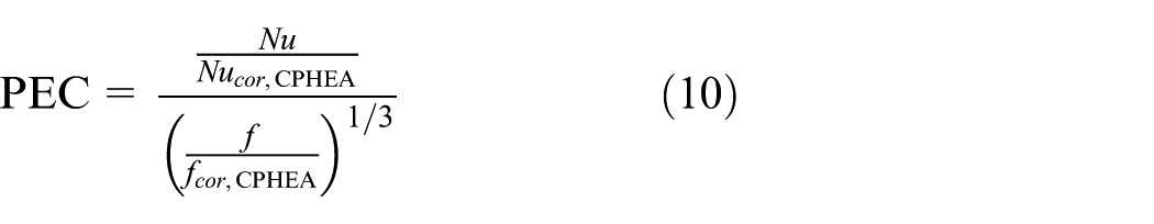
where the reference Nu and f are calculated based on the correlations of CPHE A. EEI, a new index to evaluate the flow and heat transfer performance of plate heat exchangers, is defined as follows 24

where k is the overall heat transfer coefficient, and pressure gradient ∇p is the pressure loss of the fluid through a unit length. A high EEI indicates the high energy efficiency of the heat exchanger. In Figure 13, the dots are the simulation results of the CPHEs. Both indexes indicate the high energy efficiency of CPHE D, which is characterized by the low flow resistance and are appropriate for low pressure drop applications. However, the differences among the CPHEs except CPHE E are not significant. Thus, the CPHEs with small l/d and d no more than 10 mm are also recommended for intense heat transfer applications, considering their larger heat transfer coefficients.

Variations of PEC and EEI of CPHEs.
Conclusion
In this study, the influences of capsule length and width on vortex patterns and the performances of CPHEs are numerically investigated. The main findings are summarized as follows:
Wake vortices, TVs, and LVs generate in the channels by the flow shearing and separation. The vortices promote the swirl and flow destabilization, exchange the fluid between the boundary layer and the mainstream, increase the fluid TKE, and enhance the heat transfer in the capsule-type plate channels.
With the increase of Re, wake vortices transform to LVs. The number of the LVs decreases and the size of the LVs increases with increasing Re or the decreasing length−width ratio of the capsule.
The correlations of Nu and f are proposed. The correlations are valid for Reynolds number from 600 to 10,000 and Prandtl number from 1 to 10 for the CPHEs with h of 2.5 mm, l/d from 1.5 to 4, and d no more than 10 mm. Nu and f decrease with the length–width ratio of capsule. In addition, both indexes PEC and EEI indicate the high energy efficiency of CPHEs with large length–width ratio of the capsule.
Footnotes
Appendix
Declaration of conflicting interests
The author(s) declared no potential conflicts of interest with respect to the research, authorship, and/or publication of this article.
Funding
The author(s) disclosed receipt of the following financial support for the research, authorship, and/or publication of this article: This work was supported by the National Key Research and Development Program of China (grant no. 2017YFF0209800).