
Abstract
In China, the rapid development of fast-metro system, along with many dynamic problems in track transition section, threatens the safe operation of the metro system. Aiming at this practical issue, this article presents an evaluation on the dynamic behaviors of elastic bars in track transition section of the fast-metro system. Primarily, an effective global–local method for evaluating the performance of elastic bar is proposed based on vehicle–track-coupled dynamics, in which two important models are established, namely, the vehicle–track transition section–coupled dynamic model and the three-dimensional finite element model of elastic bar. Then, the dynamic property of elastic bar in track transition section of the fast-metro system is evaluated employing the proposed method, focusing on the fastener force, dynamic displacement of elastic bar, and stress of elastic bar. Finally, fatigue analysis is conducted to evaluate the service life of elastic bar in track transition section. Results show that the proposed global–local method is effective to evaluate the dynamic behaviors of elastic bar in track transition section in fast-metro system. Impact appears when vehicles run through the track transition section and it mainly influences the two fasteners on each side. Operational direction of vehicle has little influence on amplitude of displacement of elastic bar. When the vehicle runs at 120 km/h, maximum stress of elastic bar is 1050 MPa, which occurs inside the rear toe. From the perspective of long-term service, traditional track transition section is not suitable for fast-metro system, which should be redesigned.
Introduction
With the operational speed above 100 km/h, fast-metro lines develop rapidly in China in recent decades, which make city traffic more convenient and more complete. For instance, the maximum operational speed of Metro Line 11 in Shenzhen has reached 120–140 km/h, and that of Metro Line S7 in Nanjing has also reached 120 km/h. Compared with slow-metro lines, the dynamic responses of the vehicle–track system in fast-metro lines are sharply increased. Therefore to effectively attenuate the vibrations, low-vibration tracks (LVTs) are adopted, such as floating-slab track (FST), elastic-supporting-block track, and so on. However, LVT cannot be designed and laid along the entire line due to its huge cost, indicating that LVT must be alternated with monolithic roadbed track (MRT). This leads to numerous track transition sections (TTSs) between LVTs and MRTs in the fast-metro lines. When metro vehicle runs through TTS, the stiffness difference between LVT and MRT sharply aggravates vehicle vibration and track vibration. As a result, the performance of fastener system is deteriorated and elastic bar may also be damaged and fractured in severe conditions, which obviously threaten the operation safety of fast-metro system.
The model construction of train–track coupled system has been a hot topic for a long time. In 1974, Jenkins et al. 1 established a simplified wheel–rail interaction by simulating track as Euler beam, based on which the influences of key parameters of the train–track system on wheel–rail force were investigated. After that, Clark et al. 2 investigated the dynamic effects of wheelflats on railway vehicles, in which an irregularity in the railhead was used to simulate a wheelflat for a range of vehicles, and load and rail stresses were monitored. Nielsen built a general and well-structured method for analysis of the vertical dynamic interaction between a train and its track. The trains studied were modeled as linear or non-linear discrete mass–spring–damper systems. For the track structure, a linear three-dimensional (3D) continuous model was established where the rails are discretely supported on an elastic foundation. 3 To investigate the dynamics of overall vehicle–track systems, Zhai et al. developed a three-dimensional vehicle–track coupled dynamics model in which the ballasted track was modeled as two parallel continuous Euler beams supported by a discrete–elastic foundation of three layers with sleepers and ballasts included. Random track irregularities expressed by track spectra were considered as system excitations by means of a time–frequency transformation technique. 4 Adopting the above technologies, plenty of railway engineering issues were investigated, including the dynamic behaviors of TTS. By now scholars around the world have conducted some investigations on the dynamic performance of TTSs. Shan et al. 5 studied the soil dynamic stress in culvert–embankment transition zone subject to uneven settlement and variation in track stiffness, and proposed corresponding control measure. Aiming at the vibration reduction effect of LVTs in TTSs, an experiment was designed and performed by Ma et al. 6 to obtain the effectiveness of a ballasted ladder track, which shows that the ladder track can effectively decrease the peak value in time–domain and has the potential effect to control environment vibration in low frequencies. Aggestam and Nielsen 7 simulated vertical dynamic vehicle–track interaction in a transition between ballasted track and slab track in time–domain using an extended state-space vector approach and optimize the key parameters in TTS system. To evaluate the combined effects of hanging sleepers and seismic inertia force on the lateral resistance of ballast in the tracks at transition zones, a series of laboratory tests was conducted by Takahashi et al. 8 on 1/5 scale models, and results reveal that the rail-buckling potential can be underestimated without the consideration of combined effects of hanging sleepers and the seismic inertia force on the lateral resistance. With the help of field test and numerical simulation, Wang and Markine 9 proposed a corrective countermeasure that can mitigate the track degradation in transition zones when differential settlement appears. A novel approach to anticipating poor track performance was presented by Paixao et al., 10 in terms of derailment risk, track degradation, and passengers comfort, at critical locations of railway lines, such as transition zones and other discontinuities, including local irregularities, which could provide crucial information for railway infrastructure managers. As a conclusion, Sañudo et al. 11 summarized the main problems and alternative solutions for TTSs in their review work. Although the above studies have proposed many valuable suggestions on optimizing the design and reducing the vibration of TTSs, few scholars paid attention to the dynamic behaviors of fasteners in TTS, which should be carefully concerned to ensure the operation safety.
To evaluate the elastic bar in TTS of fast-metro system, a global–local method based on the vehicle–track coupled dynamics and finite element method is proposed in this work. Primarily, the implementation process and detailed description of the proposed method is presented in section “Global–local method for dynamic evaluation of elastic bar in TTS.” On this basis, the dynamic behaviors of elastic bar in TTSs are evaluated in the next section, and a simplified investigation of service life of elastic bars is further conducted in section “Simplified investigation of service life of elastic bar in TTS in fast-metro system.” Finally, some interesting conclusions are reached in the last section.
Global–local method for dynamic evaluation of elastic bar in TTS
A reasonable interaction model is required to accurately obtain the dynamic responses of elastic bar. In this part, aiming at accelerating the computation and ensuring the computational accuracy, a global–local method for dynamically evaluating the performance of elastic bar in TTS is proposed, which consists of two important models, that is, a global model of vehicle–TTS system and a local model of elastic bar. The general framework of the proposed method is shown in Figure 1, where the dynamic displacement of elastic bar plays an important role in connecting the two models.
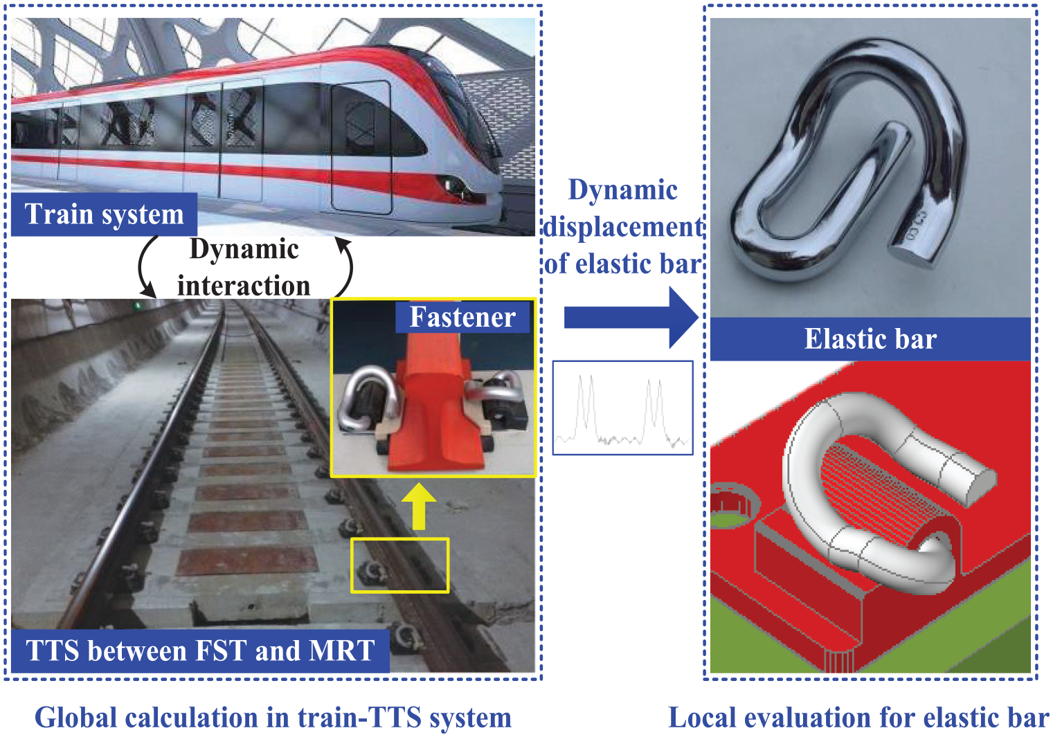
General framework of the global-local method for investigating behaviors of elastic bar.
Implementation process of the proposed method
As seen in Figure 1, two calculations are conducted in this proposed method and the implementation process is illustrated in Figure 2. From this process, two important models should be carefully established, namely, the vehicle–TTS model (the global model) and the finite element model of elastic bar (the local model). In the calculation, the vehicle–TTS dynamic model should be solved first to obtain the dynamic displacement of elastic bar, which is then imported to the elastic bar model as boundary conditions. This indicates that the calculation is conducted in two steps: (a) to solve the global model and obtain displacement of elastic bar and (b) to solve the local model to evaluate the performance of elastic bar. Hence, the modeling details of the above two models are described in the following two sections.

Implementation process of the proposed method.
Dynamic interaction between running vehicle and TTS
A two-dimensional (2D) vehicle–TTS coupled model is established in this part, which consists of a vehicle submodel, a TTS submodel and a wheel–rail interaction module, as seen in Figure 3. TTS between FST and MRT is modeled in this work. It should be stated that the springs, including fasteners and supporting springs under floating slabs, are regarded as linear springs which is accurate enough to solve engineering problems.3,4,6,11

A 2D vehicle–TTS coupled model.
Vehicle submodel
The vehicle is modeled as a mass–spring–damper system consisting of a car body, two bogie frames, four wheelsets, and two-stage suspensions, as shown in Figure 3. Each vehicle has 10 degrees of freedom (DOFs), including the vertical and pitch motions of the carbody and two bogie frames and the vertical motion of each wheelset. The dynamic equations for all the seven bodies are given as following. 12
Vertical motion of car body

Pitch motion of car body

Vertical motion of front frame

Pitch motion of front frame

Vertical motion of rear frame

Pitch motion of rear frame

Vertical motion of first wheelset

Vertical motion of second wheelset

Vertical motion of third wheelset
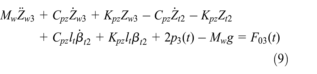
Vertical motion of fourth wheelset
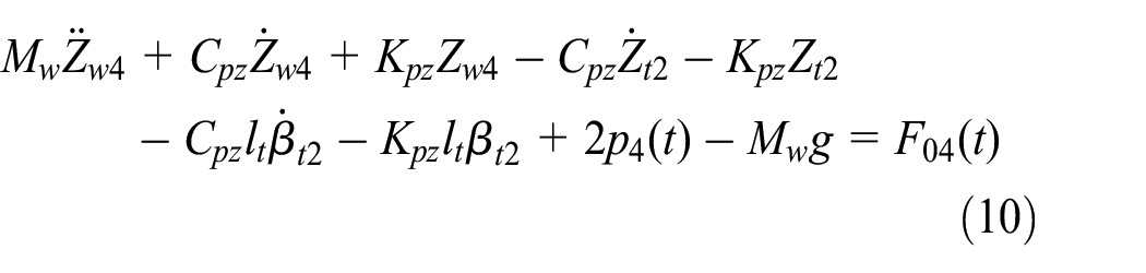
where Z and β are the vertical displacement and pitch angle; M, C, and K represent mass, damping, and stiffness of each body, respectively; J is the moment of inertia; subscript “c,”“t,” and “w” denote car body, frame, and wheelset, respectively; Cpz and Csz are the damping of the primary suspension and the secondary suspension; Kpz and Ksz are the stiffness of the primary suspension and the secondary suspension. lt is the wheel-base and lc is the length between bogie centers.
TTS submodel
Vibration equation of rail
The rail is modeled as Euler beam, and discretely supported by fasteners which are simulated as linear spring-damping elements. 13 The vibration equation of rail is given as

where Zr(x, t) is vertical displacement of the rail; mr is the rail mass per unit length; EIy is the rail bending stiffness to Y-axle; Frsi(t) is the vertical dynamic force of the ith fastener; pj(t) is the jth wheel–rail vertical force; xi and xwj are the locations of ith fastener and jth wheelset; and δ(x) is the Dirac delta function.
The mode superposition method is adopted to simplify equation (11) and the modes of vibration of the rail is expressed by

And further, the dynamic displacement of rail is written as
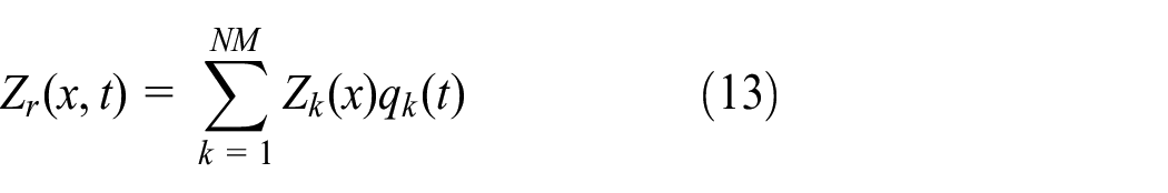
where NM is the cut-off number of modes and qk(t) is the canonical coordinate of rail vibration mode.
Hence, equation (11) is finally simplified as follows, which is can be solved with step-by-step numerical method

Vibration equation of slab
Floating slab is simulated as free-beam laid on elastic support, as seen in Figure 4.

Forces applied on floating slab.
The vibration equation of slab is given as

where EsIs is the bending stiffness of slab; Zs(x, t) is displacement of slab; Ms is the mass of each slab; Ls is the length of slab; ks and cs are stiffness and damping of vibration absorbers, respectively; n0 is the number of fasteners on each slab.
Also adopting mode superposition method, the vibration mode of free-beam is given as 4

And further equation (15) is finally simplified as

where Tn(t) is the generalized coordinate of slab vibration mode.
Wheel–rail interaction
The vehicle system and the TTS system are coupled by wheel–rail interaction, which can be described by the non-linear Hertz contact theory. Therefore, the wheel–rail force is determined by
where G is the contact constant of wheel and rail and δZ(t) is the elastic compression deformation, which is written as

where Zw(t), Zr(t), and Z0(t) represent the wheel displacement, the rail displacement, and the track irregularity at the same position, respectively.
Numerical integration
To solve the above dynamic equations, the Zhai 14 method, which is an explicit integration method, is adopted to solve the equations of the vehicle–TTS model, given as
where X, Ẋ, and Ẍ are the generalized displacement, velocity, and acceleration of the dynamic system, respectively; Δt is the time step; the subscripts (n − 1), n, and (n + 1) represent the previous two steps (t = (n − 1)Δt, t = nΔt) and the present step (t = (n + 1)Δt); φ and ψ are independent parameters that control the stability of the algorithm. To guarantee the synchronism of the calculations for each part of the coupled system, the time steps of the two numerical integration methods are both set to be 1 × 10⁻⁴ s. 13
Precise modeling of elastic bar in TTS
An accurate local model for elastic bar is important to dynamically evaluate its property. Based on finite element method, the elastic bar is model by 3D solid element according to its actual installation process, as shown in Figure 5.

FE model of elastic bar.
This model details are listed below:
This model consists of 8943 nodes and 43,961 elements.
In Area 1, the movement along radial direction is restrained and small slide along circumference direction is allowed.
In Area 2, small slide in plane is allowed for bottom nodes.
Clamping force and dynamic displacement of elastic bar calculated by the global model are applied in Area 3.
Dynamic behaviors of elastic bar in TTS
Adopting the above vehicle–TTS model and FE model of elastic bar, the dynamic behaviors of elastic bar in TTS are investigated in this part.
Parameters adopted in calculations
The type-A metro vehicle is adopted as the operation vehicle, whose dynamic parameters are given in Table 1. The vehicle runs in two directions, that is, from FST to MRT and from MRT to FST.
Key parameters of the type-A metro vehicle.
TTS between FST and MRT is adopted as the research object in this work, whose parameters are listed in Table 2.
Key parameters of the TTS.

The material of the chosen type-e elastic bar is 60Si2Mn, whose material property is given in Table 3.
Material property of the elastic bar.
Evaluation of elastic bar in TTS in fast-metro system
Adopting the established vehicle–TTS model and FE model of elastic bar, the dynamic behaviors of elastic bar in TTS in fast-metro system are investigated. To better illustrate the results, fasteners are numbered in Figure 6. The fasteners on MRT are numbered as FRi, while those on FST are numbered as FLi. The longer the distance between the fastener and the center line is, the larger the number is.
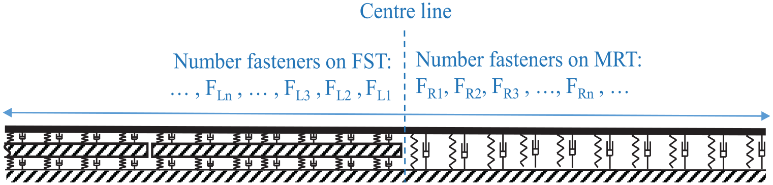
Numbering rule of fasteners.
The fastener forces at different locations are given in Figure 7. As seen from the results, if the vehicle runs from FST to MRT, the fastener force of FR1 is much larger than those of FL1 and fastener outside TTS, and the effects of four wheelsets are obviously presented. This indicates that a head-on impact appears when the vehicle runs from small-stiffness section (FST) to larger-stiffness section (MRT), and the impact mainly affects the fastener on larger-stiffness section. While if the vehicle runs in the opposite direction, the fastener force of FR1 is also larger than that of FL1. However, only two amplitudes are obviously shown, this is because the small stiffness of FST makes the rail deformation more compatible. Another interesting phenomenon should be noted is that the force of FL1 shows a great value in the opposite direction, which is caused by the drop impact of vehicle running from larger-stiffness section to small-stiffness section.
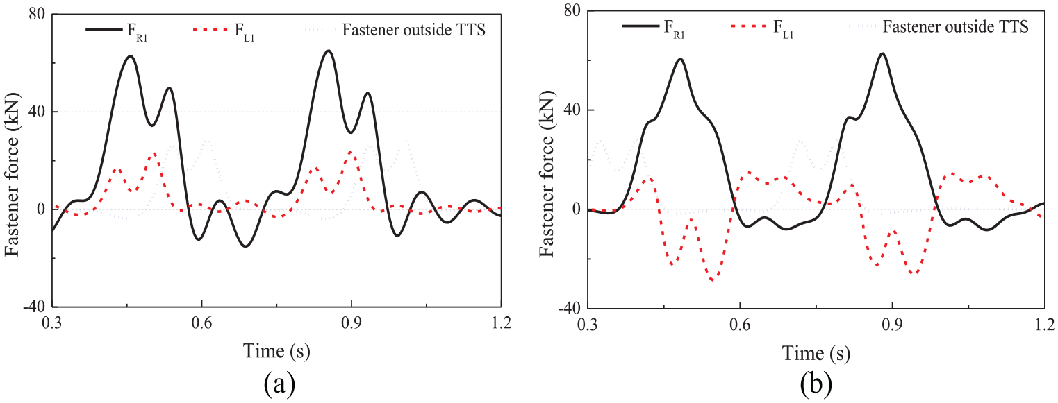
Fastener forces at different locations: (a) Vehicle runs from FST to MRT and (b) vehicle runs from MRT to FST.
Then, the amplitudes of fastener forces are illustrated in Figure 8, from which it can be clearly seen that the forces of FR1 are the largest no matter how the vehicle moves, while the forces of FL1 are the smallest. TTS mainly influences two fasteners on each side due to the sudden change of stiffness subject to running vehicles.

Amplitudes of fastener forces.
Further, the dynamic displacements of elastic bar at different locations are displayed in Figure 9. As shown in this figure, the displacement of elastic bar at FR1 location is always larger than that at FL1 location when the vehicle runs in different directions. This result shows a good agreement with the performance of fastener force. Moreover, the amplitudes of displacement of elastic bar at different locations are given in Figure 10. It can be seen from the result that the maximum displacements of elastic bar at different locations are almost the same when the vehicle runs in different directions, indicating that the operation direction of vehicle has little influence on amplitude of displacement of elastic bar.
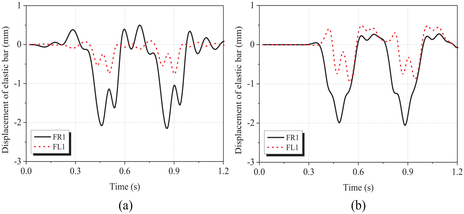
Displacement of elastic bar at different locations: (a) Vehicle runs from FST to MRT and (b) vehicle runs from MRT to FST.

Amplitudes of displacement of elastic bar at different locations.
As seen from the above results, the fastener force and dynamic displacement of elastic bar at FR1 location are the largest. It should be stated that the displacements of elastic bar and rail, rather than the fastener forces, are well coordinated according to the actual behavior of the mechanical system. Thus, in the following calculations with 3D FE model of elastic bar, the displacement of elastic bar FR1 location is adopted as the displacement boundary condition. Figure 11 shows the stress nephogram of elastic bar when the maximum stress appears. It can be seen that the maximum stress of elastic bar is 1050 MPa, which occurs inside the rear toe. The value is smaller than the tensile strength and yield strength of the type-e elastic bar, indicating that the safe operation in TTS in fast-metro system can be ensured.
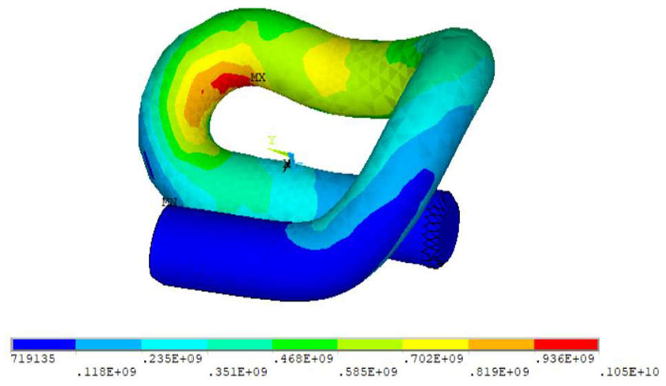
Stress nephogram of elastic bar when the maximum stress appears.
Simplified investigation of service life of elastic bar in TTS in fast-metro system
As known from the above evaluation, the maximum stress of elastic bar is 1050 MPa, which is close to the yield strength of the material, indicating that the fatigue of type-e elastic bar in TTS in fast-metro system should be seriously investigated to guarantee the long-term use of elastic bar. In this part, the service life of elastic bar in TTS is calculated with a simplified method.
The fatigue behavior of elastic bar in this work is analyzed adopting the classical S–N curve and power function, as follows

where α and C are constants of the material. Further, the function can be written in logarithm form

where a and b are also the constants of the material.
With abundant tests, China Academy of Rail Science gives the key parameters of P–S–N curve for 60Si2Mn, 15 as listed in Table 4.
Parameters of P–S–N curve of 60Si2Mn.
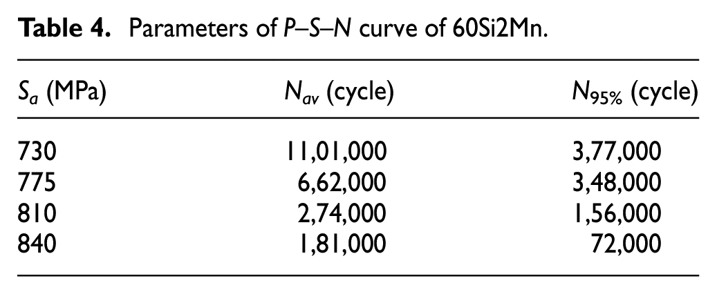
Adopting the parameters in Table 4 and equation (22), the S–N curve with survival rate of 95% is described by

It should be underlined that in actual engineering, the initial stress has great influence on the service life of structures, thus the stress amplitude in equation (23) should be modified. In this research, the Goodman expression is employed to modify the stress amplitude, as seen in equation (24)

where Sm is the mean value of cyclic stress, Sb is the tensile strength, and S−1 is the modified stress amplitude.
As known from the above calculations, the maximum and minimum stresses of rear toe section are calculated to be 1050 and 535 MPa, respectively. Adopting equation (24), the modified stress amplitude is finally calculated to be 681.22 MPa. Further, the cycle index is calculated as 10,93,956.4 by equation (23), which is much smaller than the designed cycle index of 50,00,000, indicating that fasteners in TTS in fast-metro system have a short service life subject to vehicles running at high speeds.
According to the current transportation capability of metro system in China, the calculated cycle index can be further converted to service timeas follows:
A metro train consists of six vehicles;
In total, 20 pairs of metro trains operate per hour on average;
Metro system operates for 17 h/day;
Metro system operates 365 days/year.
Adopting the above data, the service life of type-e elastic bar at FR1 location is calculated as 134 days, that is, 4.47 months. As seen from the result, the service life of type-e elastic bar in TTS in fast-metro system with operation speed of 120 km/h is only 134 days, indicating that the designs of traditional TTSs are not reasonable for fast-metro system, which should be redesigned, and this is also the research emphasis in the authors’ further work.
Conclusion
A dynamic evaluation of elastic bar in TTS in fast-metro system has been presented in this work. Primarily, an effective global–local method for evaluating the behaviors of elastic bar has been proposed, in which two important models have been established, namely, the vehicle–TTS coupled dynamic model and the 3D FE model of elastic bar. With the proposed research method, the dynamic performance of elastic bar in TTS in fast-metro system has been evaluated, in which the fastener force, dynamic displacement of elastic bar, and stress of elastic bar have been paid special attention to. Finally, the fatigue property of elastic bar has been investigated. Some interesting conclusions are reached, which are as follows:
The proposed global–local method is effective to evaluate the dynamic behaviors of elastic bar in TTS in fast-metro system.
Impact appears when vehicles run through TTS, which mainly influences two fasteners on each side. Fastener force of FR1 is the largest, while that of FL1 is the smallest. Operational direction of vehicle has little influence on amplitude of displacement of elastic bar.
Maximum stress of elastic bar is 1050 MPa, which occurs inside the rear toe. The value is smaller than the tensile strength and yield strength of the elastic bar, indicating that the safe operation in TTS in fast-metro system can be ensured.
From the perspective of long-term service, traditional TTS is not suitable for fast-metro system, which should be redesigned.
Footnotes
Handling Editor: James Baldwin
Declaration of conflicting interests
The author(s) declared no potential conflicts of interest with respect to the research, authorship, and/or publication of this article.
Funding
The author(s) disclosed receipt of the following financial support for the research, authorship, and/or publication of this article: This work was funded by Basic Natural Science and Frontier Technology Research Program of the Chongqing Municipal Science and Technology Commission (Grant number: cstc2018jcyjAX0271), the Science and Technology Research Program of Chongqing Municipal Education Commission (Grant number: KJQN201900719), the open research fund of State Key Laboratory of Traction Power (Grant number: TPL1901), the open research fund of Chongqing Key Laboratory of Railway Vehicle System Integration and Control (Grant number: CKLURTSIC-KFKT-201804), the Project of Fund Cultivation of Chongqing Jiaotong University (Grant number: 2018PY14).