
Abstract
The nozzle region of a reactor pressure vessel experiences higher and more complex stresses than the remaining part of the reactor pressure vessel. If a corner crack is postulated in the nozzle region, it is necessary to consider the potential strong influence of constraint on fracture behavior due to inelastic deformations of crack tip. In accordance with the requirement of probabilistic fracture mechanics, Weibull stress in local approach to fracture is analyzed with the consideration of constraint effect. Conventional fracture analysis is also carried out using a three-dimensional crack model, and the fracture driving forces (KI and J) and T-stress are obtained. Weibull stress along the crack tip is also computed by three-dimensional models. The modified boundary layer model with plastic correction is developed for a corner crack in the reactor pressure vessel nozzle. Under the J-T stress field from three-dimensional models, Weibull stress values obtained using the modified boundary layer model are compared and discussed with that by three-dimensional models. It is found that the modified boundary layer model can effectively predict the Weibull stress under the J-T stress field, which simplified the Weibull stress calculation process for complex structures.
Introduction
The potential failure by cleavage fracture is a key issue in the structural integrity assessment of reactor pressure vessels (RPVs) in nuclear power plants. RPVs experience a wide range of pressurized thermal shock (PTS) transients that impose severe cooling concurrent with or followed by significant pressure changes in the vessel. Combined with a reduction of fracture toughness from years of radiation embrittlement, PTS transients pose a potentially significant challenge to the structural integrity of reactor pressure vessel (RPV) during the long-time operation. 1 In addition, the safety goals of operating nuclear plants are usually defined by core damage frequency and large early release frequency of fission products, which need probability risk assessment. Therefore, probabilistic fracture mechanics is used to develop PTS screening criteria and pressure–temperature limit. 2
The failure criterion in the probabilistic assessment of RPV integrity employs conventional linear elastic fracture mechanics by comparison of crack driving forces (such as stress intensity factor KI) calculated for assessed points along the crack front with its allowable value (fracture toughness KIC or KIa).3,4 There are many uncertainties that should be considered including material chemical composition, mechanical properties, loads, crack sizes, and so on. Monte Carlo techniques are usually used to estimate the increase in failure probability as the vessel accumulates radiation damage over its operating life. 5 The conventional methodology clearly simplifies structural integrity assessment, but it has limited ability to predict the potential strong influence of constraint on fracture behavior due to inelastic deformations of crack tip. 6 In general, a second (e.g. J-T, J-Q, and J-A2) parameter can be used to quantify the crack tip constraint of engineering structures. However, probabilistic assessment requires a huge number of finite element (FE) analyses to obtain these parameters, particularly for Monte Carlo simulation.
The local approaches to cleavage fracture consider the local crack driving force and material properties in the fracture process zone (FPZ), which have been applied to constraint corrections. The local crack driving force couples the (local) fracture stress with remote loading (such as the J-integrity) in terms of the Weibull stress σw as a probabilistic fracture parameter directly connected to the statistics of microcracks. Ruggieri and Dodds 7 summarized recent advances in the local approach to cleavage fracture modeling, illustrated by selected examples of application to predict constraint effects on cleavage fracture toughness for typical pressure vessel steels. Qian et al. 8 compared crack tip constraints in different specimens and structures with global and local approaches under uniaxial and biaxial loadings. The advantage of local approaches is that Weibull stress can be transferred from one constraint level to another according to the failure probability. 9 Therefore, the failure probability can be easily obtained by Weibull stress.
Nevertheless, calculation of Weibull stress is the key of the application of the local approaches, which requires detailed elastic–plastic FE analysis of three-dimensional (3D) RPV models containing cracks. Therefore, it is necessary to develop a simplified calculation method to predict Weibull stress for these 3D models. Some approximate two-dimensional (2D) models have been proposed,10–12 such as the modified boundary layer (MBL) model, single-edge notched tension model, and axial cross-section cylinder model. It should be ensured that asymptotic stress fields near the crack tip of a 2D crack model are similar to those of a 3D crack model. 13 However, as the plastic zone in the MBL model increases in size, the crack front stress field never interacts with the geometric boundary of the model.
The RPV is mainly composed of a cylinder, shell cover, nozzle, and various components. The nozzle is a component that connects the RPV cylinder and the pipe, and includes geometrically irregular corners connected to the cylinder. Therefore, the nozzle region of an RPV experiences higher and more complex stress conditions than the remaining components of the RPV. In this article, the MBL model with plastic correction is developed for a corner crack in the RPV nozzle under internal pressure. Conventional fracture analysis is carried out using a 3D crack model, and the fracture driving forces (KI and J) and T-stress are obtained. Weibull stress along the crack tip is also computed by 3D models. Under the J-T stress field, Weibull stress values obtained using the MBL model are compared and discussed with that by 3D models.
Weibull stress and constraint
Weibull stress model
Under the action of external load, the local stress concentration will be caused when the crack tip or the FPZ of the tip is deformed plastically, which will cause dislocation and slip movement of the tiny carbide particles and impurities existing in the material and form microcracks. Due to the local heterogeneity of the microstructure in the actual material, in the case of continuous plastic deformation, a large number of microcracks with random distribution and different sizes are formed in the fracture process area. Therefore, the fracture resistance of the material and the shape, size, and direction distribution of carbide particles or impurities in the material determine the failure probability of the material.14,15 For this reason, the Weibull stress σw is proposed by Beremin group and defined as the two-parameter cumulative failure probability of the driving stress of crack tip extension in the usual sense7,16

where m and σu are Weibull modulus and scale parameters depended on the material properties and temperature. The driving force σw of the crack tip is defined as

where V0 represents the reference volume and takes a value of unity here for simplicity. Vp stands for FPZ, which is defined as

where

where ne represents the number of units in the rupture process zone and
For the relationship between Weibull stress and stress intensity factors, total Weibull stress and local Weibull stress are defined in this work. The total Weibull stress is defined by the FPZ which adopts the volume domain containing the overall crack front. The local Weibull stress is calculated at crack tip with the FPZ of the region perpendicular to the crack front, which is similar to the calculation of J-integrity for 3D crack models. A diagrammatic sketch is shown in Figure 1. The FPZ for total Weibull stress uses the summary of all the regions A1 to A n , which for local Weibull stress only for a single region.
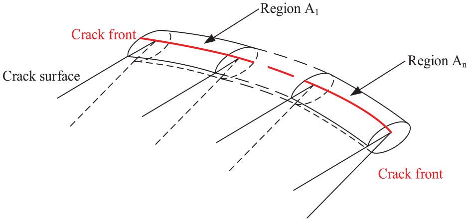
The diagram of crack front for total and local Weibull stress.
Constraint based on fracture mechanics
Neglecting higher order terms of the Williams extension, 18 the elastic stress field can be expressed in the form

The T-stress is the second term in the Williams expansion and is used for in-plane constraint analysis. Karstensen et al. 19 showed J-T characterization of crack tip stress fields failed at high levels of deformation. However, the plastic zone radii under the design cases are certainly small as compared to the thickness of RPV, 5 indicating the appropriateness of J-T characterization.
FE modeling
RPV nozzle with corner crack
A typical RPV with corner crack near the nozzle was modeled in this article. To simplify the problem, the cylinder is assumed to be made of parent material without weld and cladding. A semicircle surface crack with crack depth a = 25 mm is postulated in the corner of the nozzle,20,21 as shown in Figure 2. The center of the crack is located at the boundary of the corner of the pressure vessel.
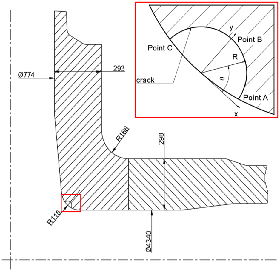
The diagram of corner crack.
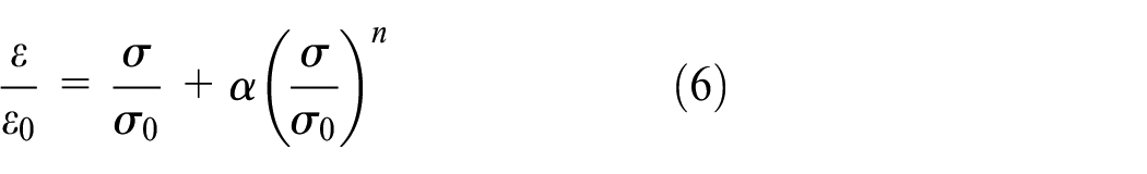
The material of the RPV is usually made of ferritic low alloy steel. A Ramberg–Osgood model (deformation plasticity model) is used to describe the stress–strain relationship of the material
where
Material properties.

In this article, geometry constraint under mechanical load is considered. As was reported, that the geometry constraint interacts with the constraint induced by the residual stress23,24 or thermal stresses. 25 Therefore, common RPV with nozzles are selected for analysis in this article. According to the symmetry of the structure, a one-fourth 3D model for the RPV with nozzle is modeling by FE software ABAQUS. A 3D 20-node reduced integration element is selected. Figure 3 shows the mesh including the crack. In order to more accurately reflect the change of the stress field at the crack tip, the mesh of the crack tip is refined. It should be noted that the absolute value of Weibull stress for elastic materials depends on the notch radius which can result in varied stress field. 26 However, for elastic–plastic materials, there is no significant difference in the stress field near the crack tip which is surrounded by a local plastic zone. This initial root radius could facilitate the numerical convergence at large plastic deformation near the crack tip. Therefore, the subsequent derivations use a notch radius of 3 μm, which is coincident with several literature works.27,28

FE model of RPV nozzle with a corner crack.
MBL model
The MBL model is usually used to characterize the small-scale yielding condition of cracked models, as shown in Figure 4. In order to eliminate the singularity of the crack tip and accelerate the convergence speed of FE calculation, the crack tip with a notch value of ρ0 is set as 3 μm. According to the definition in the literature,17,29 it is set as

where E is the elastic modulus; v is Poisson’s ratio; r and θ, respectively, represent the location and angle of distance to the crack tip. The stress intensity factor KJ for plane strain could be obtained based on the J-integral value through the


MBL model (a) whole model mesh and (b) local mesh around the crack tip.
Results and discussion
RPV nozzle model
To verify the 3D FE model, the stress intensity factor solution of point B at the crack tip in the 3D FE model of the RPV nozzle is compared with the corresponding stress intensity factor solution in API 579, 30 as shown in Figure 5. It can be found that the results are in good agreement.

Comparison of stress intensity factors of finite element model.
In order to determine the constraint by T-stress, linear elastic fracture mechanics analysis of the RPV model with a corner crack is carried out. The stress intensity factor KI and T-stress are obtained under internal pressure p = 20 MPa, as shown in Figure 6. It can be found that the KI values along the crack front accord with the bathtub curve, but the T-stress along the crack front displays a reversed trend compared with the KI values along the crack front. The KI value reaches the lowest value near the crack center θ = 0.5π, while T-stress has a lower value near the surface points A and C than that of deep point B. As expected, with the increase in the T-stress, the constraint increases and thus the crack center shows higher constraint. Then, the stress intensity factor reaches the lowest value near the crack center.
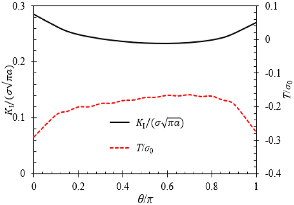
K I and T-stress along crack front.
A normalized measure of structural constraint β is defined by

According to the results of linear elastic analysis, the value of constraint parameter β can be evaluated, which will be used in MBL model. Elastic–plastic FE analysis is also carried out to calculate J-integral value, with the consideration of the plastic effect on the fracture parameters. Then, the J-integral value is used to estimate KJ by equation (8). Figure 7 shows the β values along the crack front under different pressures for elastic analysis and elastic–plastic analysis. With the increase in the pressure, the plastic zone area increases and the differences of β values between elastic analysis and elastic–plastic analysis become more distinct.

Values of constraint parameter β along crack front.
The Weibull stress computed over the entire perimeter of the crack for the RPV model is also calculated on the elastic–plastic FE analysis, as shown in Figure 8. With the increase in the pressure, the Weibull stress increases and thus the structure will undergo higher failure probability. The effect of the Weibull modulus m on Weibull stress is also investigated in Figure 8. As expected, larger m values give higher Weibull stress, which promote strongly the relative contribution of material right at the peak stress location ahead of the blunting crack front to the Weibull stress value. 12

Total Weibull stress versus internal pressure with different Weibull moduli.
To construct the relationship between KI-T field and Weibull stress, pointwise values of the Weibull stress along the crack front are calculated by dividing the crack front into 11 segments. Figure 9 shows local Weibull stress along the crack front with Weibull modulus m = 15. It can be seen from Figures 8 and 9 that local Weibull stress at the crack front is the same as total Weibull stress. With the increase in the pressure, local Weibull stress at the crack front increases. At the same time, the range of local Weibull stress values at the crack front is also close to total Weibull stress value. Therefore, it is possible to use total Weibull stress and local Weibull stress to characterize geometric constraints. In addition, as mentioned in the previous article, there is a similar trend with β values along the crack front, which indicates that it is suitable to characterize geometry constraint by Weibull stress.

Local Weibull stress along the crack front.
MBL model
According to the values of constraint parameter β, the displacement boundary conditions controlled by KI and T-stress are applied on the MBL model. Figure 10 shows the Weibull stress for different points. It can be found that under the condition of Weibull modulus m = 10, 15, and 20, the results of MBL model can better predict the Weibull stress value of RPV, where the maximum error does not exceed 2%. Therefore, the MBL model can be applied to the Weibull stress prediction of the RPV nozzle with crack under internal pressure.

Weibull stress estimated by MBL model: (a) point A and (b) point B.
Conclusion
In accordance with the requirement of probabilistic fracture mechanics, Weibull stress in local approach to fracture is analyzed with the consideration of constraint effect for the corner crack in RPV nozzle. Stress intensity factors and T-stress are evaluated by 3D FE models with crack. Total and local Weibull stress along the crack tip is computed by 3D crack models. The MBL model with plastic correction is developed for a corner crack in the RPV nozzle. For the case employed in the study, the following conclusions can be drawn:
According to the FE analysis of 3D crack model, the crack surface points show lower T-stress and higher values of stress intensity factor, which indicates constraint loss. With the increase in the pressure, the plastic zone area increases and the constraint differences between elastic analysis and elastic–plastic analysis become more distinct.
Local Weibull stress is defined by dividing the crack front into several segments which can be used to construct the relationship between KI-T field and Weibull stress. It shows that there is a similar trend with constraints characterized by T-stress along the crack front, which indicates that it is suitable to characterize geometry constraint by local Weibull stress.
Under the KI-T fields along the crack front from 3D crack model, a 2D crack model based on MBL model is proposed to predict the Weibull stress. The results show that the proposed model can effectively predict the Weibull stress to simplify the Weibull stress calculation process of complex structures.
Footnotes
Handling Editor: José Correia
Declaration of conflicting interests
The author(s) declared no potential conflicts of interest with respect to the research, authorship, and/or publication of this article.
Funding
The author(s) disclosed receipt of the following financial support for the research, authorship, and/or publication of this article: The authors are grateful to the support from the National Natural Science Foundation of China (Nos 51605435 and 11602219) and Natural Science Foundation of Zhejiang Province (No. LQ16A020004).